1
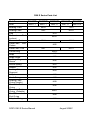
HARBIN ROPV INDUSTRY DEVELOPMENT CENTER
ROPV R80 E Series User Manual
For Use with the Following ROPV Pressure Vessel Models:
R80 150E
R80 250E
R80 300E
R80 400E
R80 450E
Headquarters
Harbin ROPV Industry Development Center
100 Hongqi St.
Xiangfang District
Harbin, China 150036
Tel: +86-451-5515-5144
Fax: +86-451-5515-5124
Email: [email protected]
Website:www.ropv.com.cn
ROPV R80 E Series Manual
August 2005C
General Product Description – R80 E Series
End Port Membrane Housing
R80 150E Design Pressure:
R80 250E Design Pressure:
R80 300E Design Pressure:
R80 400E Design Pressure:
R80 450E Design Pressure:
150PSI / 1.0Mpa / 10Bar (at 120°F / 49°C)
250PSI / 1.7Mpa / 17Bar (at 120°F / 49°C)
300PSI / 2.1Mpa / 21Bar (at 120°F / 49°C)
400PSI / 2.8Mpa / 28Bar (at 120°F / 49°C)
450PSI / 3.1Mpa / 31Bar (at 120°F / 49°C)
Min. Operating Temp.:
Max. Operating Temp.:
Factory Test Pressure:
20°F / -6°C
120°F / 49°C
ASME: 1.1x Design Pressure
Standard: 1.5x Design Pressure
6X Design Pressure
3 – 11
2 – 12 (less than 30 minutes)
Burst Pressure:
Operating pH Range:
Cleaning pH Range:
General Warning – High Pressure Membrane Housing
ROPV Pressure Vessels are designed to provide safe operation over a long service life if
properly installed, operated, and maintained. The vessel may cause loss of life, severe
bodily harm, or property damage if not correctly installed, operated, or maintained. Read and
understand all guidelines provided in the vessel User Manual. Observe every precaution
contained therein. Failure to do so may result in malfunction and potential catastrophic
failure. It is recommended that only qualified technicians experienced in servicing hydraulic
systems work with this vessel. Misuse, incorrect assembly, or use of damaged/corroded
components may result in catastrophic failure.
Vessel Use and Precautions
•
•
•
•
•
•
•
•
Positive pressure up to the design pressure (PSI) of the specific model being used.
Accommodates standard 8” nominal diameter spiral-wound element.
The required vessel/element interface hardware is supplied with the vessel. Ensure
that an element adapter is installed at each end of the vessel before use.
Vessel expands under pressure and careful consideration must be taken when
installing straps/saddles and system connection piping.
Installation with the straps/saddles provided is strongly recommended
Vessel should not support any other system components. Connections should be
non-load bearing.
Periodic inspection of the vessel end closure is recommended to ensure all parts are
dry and free of corrosion.
Failure to understand and follow all precautions may void warranty and result in
catastrophic failure of the vessel.
ROPV R80 E Series Manual
August 2005C
•
•
•
•
•
•
•
•
•
•
•
•
•
•
•
These guidelines are subject to change. Please check with ROPV to ensure that the
User Manual is the latest version for the vessel model being used.
Mount vessel using strap/saddle hardware provided and span recommended in the
engineering drawing.
Do not over tighten the straps – vessel must be allowed to expand under operation.
Maximize the connection flexibility to allow for vessel growth under pressure.
Align the end ports with the system manifold, correcting any misalignment before final
installation.
Provide overpressure protection in the system safety devices.
Inspect end closures regularly for signs of corrosion. Immediate corrective action
and/or replacement is suggested in case of corrosion.
Relieve system pressure before working on the vessel.
Do not attempt to over-tighten the Permeate Port connections as this may damage the
end closure. One turn past hand tight should be sufficient.
Ensure that the Trust Cone is installed on the downstream end of the vessel.
Never operate the vessel in excess of its ratings. This may void the warranty and
cause bodily or property damage.
Do not operate the vessel permeate port over 125PSI.
Flush the vessel with permeate before system shutdown to reduce the chance of
corrosion.
Do not install the vessel in direct sunlight.
Operate the vessel within the recommended pH range - Operating pH Range: 3 – 11,
Cleaning pH Range: 2 – 12 (less than 30 minutes).
ROPV R80 E Series Manual
August 2005C
Head Removal
Step 1 Shut Down System and Relieve System Pressure – The system must be shut
down and all pressure relieved before conducting any maintenance or repair on the vessel.
Step 2 Disconnect Permeate Piping – The system permeate piping must be carefully
removed from the permeate port of the vessel.
Step 3 Inspect End Closure – The end closure should be inspected for any signs of
corrosion or damage. Surface corrosion can be removed with a wire brush, while flushing
with water. Damaged components should be replaced with approved components from
ROPV.
Step 4 Disconnect Locking Screws – Each of the three locking segments is held in place
with a single locking screw. The locking screws can be unthreaded using a standard M6
7/32” hex wrench. The locking screws should be unthreaded from the head only, not from
the locking segment. The locking screw and locking segment can be removed together.
Step 5 Remove the Locking Segment/Screw Assemblies – The locking segment/screw
assemblies should be easily removed from the retaining groove. Should the assemblies be
difficult to remove, it may be necessary to rock the head slightly or tap the head inward with a
rubber mallet. Be careful when using metal tools, avoiding leveraging against the sidewall of
the vessel or scratching the inside surface of the bell area.
Step 6 Remove the Head Assembly with One of the Following Techniques
ROPV Head Removal Tools – A set of head removal tools is available from ROPV. While
not necessary for head removal, they have proven an effective and easy way to remove the
vessel head without causing any damage to the vessel.
ROPV R80 E Series Manual
August 2005C
Picture 1
Picture 2
Picture 3
Picture 1 – Detail picture of head removal tools.
Picture 2 – Thread the center piece into the permeate port of the head assembly, to hand
tight. Do not over tighten the center piece.
Picture 3 – Position nut, bearing rod, and bearing block as shown. Turn bearing rod
clockwise. The head will move with the bearing rod as it moves toward the end of the vessel.
You will be able to remove the head once it has cleared the retaining groove area of the
vessel.
Alternative Head Removal – It is possible to remove the head assembly without the ROPV
head removal tools. The feed/concentrate can be used as a handle to pull the head from the
vessel. A strong tug lay be required to break the head seal bond but do not use excess force
on the feed/concentrate port. A slight rocking motion will help break the seal bond.
Complete Head Assembly with Adapter
ROPV R80 E Series Manual
August 2005C
Head Disassembly and Inspection
Step 1 Remove the Head O-ring – Use a non-metallic, rounded tool to start the o-ring out of
the o-ring groove. Once a small portion of the o-ring has been lifted out of the groove, use
your hand to work the remainder of the o-ring out of the groove. Damaged or cut o-rings
must be replaced during re-installation of the head.
Step 2 Remove Adapter – Grasp the adapter and slowly pull from the bearing
plate/permeate port. A slight rotating motion may ease the removal of the adapter. There is
a set of double o-rings on the inside diameter of the permeate port that must be inspected for
damage once the adapter is removed. Damaged o-rings must be replaced before reinstallation.
Step 3 Remove Bearing Plate – Use a wrench to remove the permeate port Locknut. The
locknut is reveres threaded (or left hand threaded) and must be turned clockwise to be
removed and counter clockwise to be installed. After removing the locknut, the bearing plate
and sealing plate can be separated.
Step 4 Remove the Permeate Port – Grasping the sealing plate, rock the permeate port
ROPV R80 E Series Manual
August 2005C
slightly and pull away from sealing plate. It may be necessary to tap the permeate port on
the smaller end with a rubber mallet to release the seal bond. Once it is removed, check the
sealing plate o-ring seated between the permeate port and the sealing plate. Inspect for
damage or foreign matter. Replacement o-rings are recommended during all head rebuilds.
Step 5 Remove the Feed/Concentrate Port – Remove the two pieces of feed/concentrate
port fixture. Grasping the sealing plate, rock the feed/concentrate port slightly and pull away
from sealing plate. It may be necessary to tap the feed/concentrate port on the smaller end
with a rubber mallet to release the seal bond.
Step 6 Clean All Components – All components should be cleaned with a mild soap
solution or clean water. The components should be air dried or dried with a lint-free towel.
Step 7 Inspect All Components – All components should be carefully inspected for signs of
corrosion and damage. Components exhibiting such should be replaced before reinstallation. All o-rings should be carefully inspected for signs of damage. It is recommended
that all o-rings be replaced during each complete servicing of the vessel. Failure to do so
may cause poor system performance.
Step 8 Inspect Inside Vessel Surface – The inside surface of the vessel should also be
inspected once the membrane elements have been removed. Special attention should be
paid to identify any scratches, damage or foreign matter. Surface scratches can be repaired
by carefully sanding the effected surface with 600-grit sandpaper. A combination of soapy
water and fresh water should be used to flush the area during sanding. Clean water should
be used to clean the area after sanding. Any extemporaneous matter can be removed with a
soft cloth, soapy water, and a clean water flush. Damaged vessels should not be used under
any circumstances.
ROPV R80 E Series Manual
August 2005C
Picture of Disassembled Head Components
ROPV R80 E Series Manual
August 2005C
Head Reassembly
Step 1 Inspect All Head Components – All head components should be free from scratches,
foreign matter, or any sign of damage. Please see Step 6 above for additional information
about cleaning head components. Scratched or damaged components should be replaced
with ROPV supplied replacement components. All o-rings should be carefully inspected for
signs of damage. It is recommended that all o-rings be replaced during each complete
servicing of the vessel. Failure to do so may cause poor system performance.
Step 2 Install Feed/Concentrate O-rings – All o-rings should be coated with a thin layer of
glycerine before installation. Care should be taken to minimize the amount of glycecrine and
any excess should be removed. One o-ring should be placed into each of the two grooves
located on the inside diameter of the feed/concentrate port hole in the sealing plate. Make
sure o-rings are completely seated in the grooves.
Step 3 Install Permeate Port O-rings – One o-ring should be placed at the base of the
threaded side of the port, at the larger diameter section of the port that seats against the
sealing plate. One o-ring should be placed in each of the two grooves on the inside diameter
of the permeate port side that is not threaded.
ROPV R80 E Series Manual
August 2005C
Step 4 Assemble Sealing plate and Permeate Port – Push the sealing plate down onto the
permeate port with the sealing plate o-ring toward the top or threaded end of the permeate
port. It may be necessary to use your body weight to seat the sealing plate.
Step 5 Assemble Feed/Concentrate Port – Place the feed/concentrate port in the sealing
plate opening and secure using the two feed/concentrate port fixtures.
Step 6 Assemble the Bearing Plate – Position the bearing plate over the sealing plate,
pushing them together so that the threaded portion of the permeate port is visible.
ROPV R80 E Series Manual
August 2005C
Step 7 Thread Lock Nut Onto Permeate Port – Lock nut should be tightened to handtightness using a wrench for the final half-turn. Do not over tighten the Lock Nut – maximum
torque guideline: 15Nm. Note that the threads of the Permeate Port are reverse or left-hand
threaded.
Step 8 Install Adapter O-rings – All o-rings should be coated with a thin layer of glycerine
before installation. Care should be used to minimize the amount or glycerine applied and
any excess should be removed. Seat one permeate port o-ring into each of the two grooves
located at the element end, outside diameter of the adapter.
Step 9 Install Adapter – The adapter should be pushed into the permeate port until the
wider diameter middle section is flush against the end of the permeate port. Simultaneously
pushing and turning the adapter will ease installation.
Step 10 Install Head O-ring – All o-rings should be coated with a thin layer of glycerine
before installation. Seat the head o-ring into the groove on the outside diameter of the head.
Complete Head Assembly with Adapter
ROPV R80 E Series Manual
August 2005C
Head Installation
Step 1 Follow All Steps Outlined in the Head Reassembly Section
Step 2 Install Head – Hold the head assembly with both hands, square to the axis of the
vessel. Push firmly with both hands until the head is correctly positioned and the retaining
groove is visible. It may be necessary to use a rubber mallet to tap the head into its engaged
position. The thrust cone must be installed with the head at the downstream end of the
vessel.
Step 3 Install Locking Kit Segments – Clean and dry the retaining groove. Position the
first locking segment so that the end section sits in the retaining groove and the screw aligns
with one of the threaded openings in the bearing plate. Use an M6 / 7/32” hex wrench to
tighten the screw until snug. Do not over-tighten – maximum torque guideline: 10Nm. Install
the two other segments in the same manner. Conduct a final tightness check of each screw
after all three segments are installed.
Step4 Reconnect Permeate Piping – Reconnect the system permeate piping to the
permeate port.
Step5 Pressurize System – A thorough pre-pressurization inspection should be conducted,
including verifying that the heads are properly installed, system piping connections are in
place, elements are installed, adapters are installed, and thrust cone is installed at
downstream end of the vessel.
Step 6 Inspect for Leaks – All connections should be free from leaks. Do not operate
leaking vessels.
ROPV R80 E Series Manual
August 2005C
Piping and Mounting Recommendations
U-bend pipe with two flexible Victaulic™ connections or flexible hose at each end.
Do not force any connections.
The Header and related piping should be self-supported.
Space strap/saddle locations using “S” dimension shown in model engineering
drawing. -4 and longer vessels have a third strap/saddle assembly, to be installed at the
center point of the vessel.
Tighten straps to hand tightness plus one turn.
Manifold span should be greater than vessel span to allow for vessel growth under
pressure.
ROPV R80 E Series Manual
August 2005C
R80 E Series Parts List
Part Name
Shell
R80150E
R80250E
R80300E
R80400E
R80450E
8044.1-7
8045.1-7
8046.1-7
8047.1-7
8047.8-14
Bearing Plate
80510
8051
Sealing Plate
8053
8053.1
Plug
Permeate
Port
Locknut
Permeate Port
Feed/Conc. Port
Fixture
Feed/Conc. Port
Thrust Ring
8013
8014.1
8064.1
8064.2
8055
8057
8057.1
8022.2
Strap
8027
Strap Screw
Locking Segment
Screw
Screw Spring
8029
Saddle
Locking Kit
Segment
Adapter
8032
Head O-ring
Sealing Plate
O-ring (Inside)
Permeate Port
O-ring
Permeate Port
O-ring (Outside)
Feed/Concentrate
Port O-ring
Adapter O-ring
8037
ROPV R80 E Series Manual
8030
8031
8033
8025
8058
8040
8062.1
8058
8043
August 2005C
ROPV Limited Warranty
Harbin ROPV Industry Development Center (hereinafter called “ROPV”) vessels (the “Product”) are warranted
to the original purchaser (the “Customer”) under normal use and if installed, operated and maintained in
accordance with applicable User Guides to be free of defects in material and/or workmanship for a period of
one (1) year from date of manufacture subject to the following. Any replacement Product or Part will be
warranted only for the remainder of the original warranty period or thirty (30) days, whichever is longer.
Exclusions from this Limited Warranty
The warranty shall be void if:
1. defects are not reported during the warranty period.
2. the Product is subject to accident, damage, incorrect installation, mishandling, abuse, misuse, negligence or
accident by any other party.
3. problems caused by modification or alteration.
4. chemical exposure or acts of nature.
5. any item manufactured by other companies.
6. wear on replaceable components under normal conditions – seals are excluded from this warranty.
Procedure for Obtaining Warranty Performance
ROPV reserves the right to determine if a reported defect is a breach of this warranty. This may require, at
ROPV’s discretion, one or more of the following: 1. an inspection or test of the Product and/or the system in
which it was installed by an ROPV representative - the customer is responsible for arranging access to the
Product. 2. an inspection or test of the product and/or the system in which it was installed by the Customer. 3.
an inspection or test of the product and/or the system in which it was installed by third party inspector appointed
by ROPV. 4. return of the Product to ROPV’s factory for inspection or testing. This is not a statement of
limitations for warranty performance and ROPV reserves the right to conduct warranty performance outside of
the items shown.
If the Product is found by ROPV to be defective under the terms of this warranty, ROPV will perform one of the
following at its option: 1. supply a substantially similar replacement part based on FOB factory terms. 2. conduct
a field repair of the Product. 3. issue a credit for the original cost of the Products. This is not a statement of
limitations for warranty performance and ROPV reserves the right to conduct warranty performance outside of
the items shown.
Products returned to ROPV for inspection or testing must be shipped freight prepaid at the Customer’s expense.
If a breach of warranty is confirmed, ROPV will bear all costs related to the inspection and testing. If the
Product failure is found to be caused by cause other than breach of warranty, all costs related to the inspection
and testing of the Product will be borne by the Customer. This includes a USD$500 per day fee and all related
travel expenses.
All reported defects must be submitted to ROPV in writing.
Disclaimer
ROPV makes no expressed or implied warranty other than that specifically set forth in this warranty statement.
ROPV disclaims any warranty of merchantability or of fitness for a particular purpose.
ROPV’s liability under the terms of this warranty shall not exceed the purchase price of the Product which are
claimed to be defective. ROPV shall not be liable for any consequential or incidental damages whatsoever,
including but not limited to injuries or damages to person or property, loss of business profits, business
interruption, loss of use, cost of removing/installing Products, or the claims of third parties.
Warranties or Representations by Others
No agent, employee, dealer, or other person has any authority to make any warranties or representations
concerning ROPV or the Product. ROPV is not responsible for such claims of warranty or representation.
ROPV R80 E Series Manual
August 2005C
ROPV R80 E Series Manual
August 2005C
ROPV R80 E Series Manual
August 2005C
ROPV R80 E Series Manual
August 2005C
ROPV R80 E Series Manual
August 2005C
ROPV R80 E Series Manual
August 2005C