1
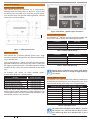
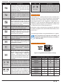
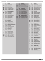
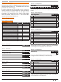
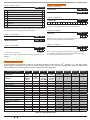
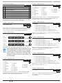
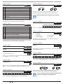
Solution 16plus Quick Start Guide To Hardware Default 1) Remove All Power To The System. AC and Battery. 2) Press and Hold The Default Push Button Down Then Apply Power To The System. 3) Release Button, The Panel Will Reset And Revert To Normal Operation When Default Is Complete. Zo n e Ar ray The feature allows you to view the condition of 16 zones at a time on a single display. From the installer programing mode press [Menu] 3-0-1 to access the zone array. Use Keys [] and [] to scroll up and down the zone bank Press [OK] or [MENU] when finished. N= NORMAL S = SHORTED A= ALARM T= TAMPER - = DISABLED To Software Default 1) Enter Program Mode. [1234 +MENU] 2) Select Factory Default Option. [MENU 7-0-4) 3) The Panel Will Reset And Revert To Normal Operation When Default Is Complete. 0000000001111111 1234567890123456 NSA-ANAT-------PRESS , OK or MENU Figure 20: Sample Zone Array Display You can disable factory defaulting using MENU 7-74. If factory defaulting has been disabled you must Note know the installer code to perform a factory default otherwise the system will need to be returned to your supplier for defaulting or you can purchase a CM255 Default Unlock Key which will unlock the panel in the field. Charges apply for defaulting if retuned to the distributor. In the above example screen, N = Zone 01 and 06 are Normal (Sealed) S = Zone 02 is Shorted A = Zone 03,05,07 are in Alarm (Unsealed) T = Zone 08 is in Tamper Alarm (Unsealed) - = Zone 04, 09-16 are Disabled (Unused) D o m e s t ic Template Defaults B a s i c R e p o r t i n g R e fe re n ce i The following table list the changes that will occur when you select domestic default. Program Option All Trouble Reports Domestic Default Value Disabled All Bypass Reports Disabled All Restore Reports Disabled Destination 1 TX Format Domestic Reporting A complete reporting template is available on the Solution Link CD or from your nearest Bosch security products outlet. Your base station will need to create a specific reporting template for this and other new model Solution panels. Point ID Table Ur999 Ur998 Ur001 - 256 Ur000 Open / Close Reports Disabled (all areas) Module Description Installer Remote User Users Quick Arm Zn301-428 User Keyfob 1 - 128 Zn891-898 Panels 1-8 Zn881-888 Keypads 1-8 Zn871-878 Ethernet 1-8 Zn861-868 GSM 1-8 D i re c t Link Programming Zn851-858 Output Expander 1-8 The panel can be programmed via the Solution Link Upload/Download software in either Direct Link or Remote Link modes. For Direct Link you will need a CM900 Direct Link module which connected the panels serial port to the PC. Zn841-848 Serial Expander 1-8 Zn831-838 Lan P/Supply 1-8 Zn821-828 RF Reciever 1-8 Zn811-818 Access 1-8 Zn801-808 X10 1-8 Zn781-788 Input Expander Zn791-798 Lift 1-8 Zn001-128 Zones System Events Route Log Only Table 10: Domestic Keypad DIP Switch Address Settings Once the cable is connected you will need to hold down the default switch on the panel for 5 seconds to initiate the programming session. See Figure 12: for the default switch location. It is also possible to initiate the programming session via [MENU 5-0-5] Start Direct Link. 14 Table 11: Basic Reporting Code Reference Listing Bosch Security Systems 09/06 BLCC100R