1
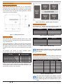
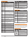
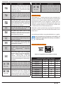
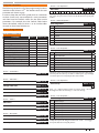
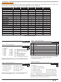
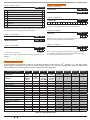
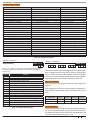
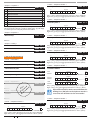
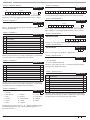
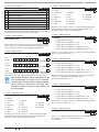
Solution 16plus Quick Start Guide Zo n e D efault Table The table below list the default values for all zone parameters in the Solution 16plus. By default, zones 5 to 16 are set as Instant zones. Zones marked as Not Used do not require EOL resistors to be fitted. Programming Option Zone 1 Zone 2 Zone 3 Zone 4 Zones 5 to 16 Zone Name Zone Type Area Assignment Pulse Count Pulse Count Time (Sec’s) Access Group Report Route Reporting Options Lockout Dialler Report Alarm Report Alarm Restore Report Trouble Report Trouble Restore Report Bypass Report Bypass Restore Delay Report Zone Options Lockout Siren Silent Alarm Inverted Seal Bypass Allowed Sensor Watch Armed When Part On Reserved Test On Exit Zone 1 1 = Delay 1 1 0 120 0 2 Zone 2 5 = Handover 1 0 120 0 2 Zone 3 5 = Handover 1 0 120 0 2 Zone 4 5 = Handover 1 0 120 0 2 Zone 5 - Zone 16 3 = Instant 1 0 120 0 2 Y Y Y Y Y Y Y N Y Y Y Y Y Y Y N Y Y Y Y Y Y Y N Y Y Y Y Y Y Y N Y Y Y Y Y Y Y N Y N N Y N Y N N Y N N Y N Y N Y Y N N Y N Y N Y Y N N Y N Y N Y Y N N Y N Y N Y Table 15: Zone Defaults MENU 3-3-2 Test RF Device Inputs > Global Input Options > EOL Value Inputs > Global Input Options > Input Options MENU 3-4-2 1 Tamper On Short N 2 Reserved N MENU 3-4-0 3 Response Time 500ms N 5 4 Reserved N 11 = 6K8 Alarm with 2K2 Tamper 5 Keyswitch Open / Close Report Y 7 = 5K6 12 = 10K Alarm with 10K Tamper 6 Reserved N 8 = 6K8 13 = 22K 7 Reserved N 4 = 2K7 9 = 8K1 14 = 3K3 with 6K8 Tamper 8 Reserved N 5 = 3K3 10 = 10K 0 = No EOL 1 = 1K0 6 = 4K7 2 = 1K5 3 = 2K2 15 = Split EOL (Parallel) (3K3 = Primary 6K8 = Secondary) Use Keys [] and [] keys or enter 0 - 15 Then Press [OK] To Program Globally The EOL Resistor For All Zones. (*** System Wide Parameter ***) MENU 3-4-1 Input Type MENU 3-5-0 0 0 = Disabled 0 0 = Latching - All On/Off 5 = Momentary All On/Off 1 = Latching - All On 6 = Momentary - All On 2 = Latching Part On/Off 7 = Momentary - Part On/Off 3 = Latching - Part On 8 = Momentary - Part On 4 = Latching Off 9 = Momentary - Off Use Keys [] and [] keys or enter 0 - 9 Then Press [OK] To Program How The Keyswitch Will Operate. (*** System Wide Parameter ***) 22 (*** System Wide Parameter ***) Inputs > PGM Input > Inputs > Global Input Options > Keyswitch Options Use Keys [] and [] to scroll up and down the option list. With option selected press ON / OFF key to enable or disable option. [] will display to indicate option set. Press [OK] To Save when finished. 1 = Latching - On/Off (RF Relay) 2 = Momentary - On/Off (RF Relay) 3 = Digiflex RF On/Off 6 = Ness Serial RF Receiver 4 = Bosch Serial RF Receiver 7 = Inovonics Serial Receiver 5 = C Type Serial RF Receiver 8 = Secure Wireless Receiver Enter 0 - 7 + [OK] to select the interface method used for the given RF receiver. The latching and Momentary options will control all areas on the system. For individual area control via RF relay you should use a keyswitch zone(s) in the area you want to control. Bosch Security Systems 09/06 BLCC100R