1
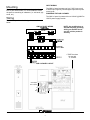
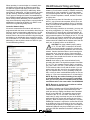
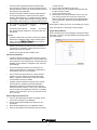
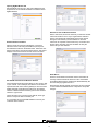
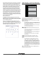
LED Display and Push Buttons
Set the PAN ID and channel list for each device in the wireless
network. Once all the routers have been programmed and the
network has had enough time to form (approximately 2 min
for each node), connect the QW1010 to the computer running
the Insight software. In the wireless module tab, click the “Poll
Network” button. A network view window will pop up. After
8.00 (approximately
in.
the network view window has loaded fully
30
seconds) it should look similar to the picture. The blue dots
displayed on the network view window represent the wireless
nodes on the network. By hovering the mouse pointer over each
node it is possible to see the TCS as well as ZigBee address.
If a node does not have a valid TCS address or is a repeater, it
will be displayed in a yellow green color. If all the nodes in the
wireless network are accounted for and show up in blue, then
the wireless network is functioning correctly and the Coordinator
14 in.
can be connected to the QD2040.
4
5
7
8
Wireless Network View
The ZigBee tree will also be displayed as a list view in the
ZigBee tab. When an address is selected from the network list
that nodes, children can be displayed by pressing the get button
12.50 in.
next to the ZigBee children box.
CPU
RESET
RX
6
ALARM
3
WIRELESS
2
TX
1
POWER
CH | ON | OVR | DESCRIPTION
Fourteen LEDs on the QWL 3.0 allow the user to view the current operating status of the QWL 3.0.
DIGITAL OUTPUTS: Along the Left hand side there are Eight
LEDs and Push button
When one of the ZigBee addresses is selected in the poll
network box it will appear in the ZigBee address section of the
page. Once the address is displayed in the ZigBee Address box
that addresses device type, firmware version, LQI, etc. can be
retrieved by hitting the associated get button.
•
The LEDs will be lit when the corresponding relay output is occupied, or physically on no matter if the channel is selected to be NO or NC.
•
The pushbuttons correspond to each of the channels
for the timed override function.
DATA: Along the Right hand side towards the bottom, there
are three LEDs
•
The RX LED indicated that the hard wired RS485 network is in Receive mode.
•
The TX LED indicated that the hard wired RS485 network is in transmit mode.
•
The Wireless LED indicates activity on the ZigBee
wires network.
ALARM: This LED indicates that a local alarm is active
19.50 in.
POWER: This LED indicated that the QWL 3.0 has power
applied
•
21.50 in.
The reset button in the lower right hand corner is
used to “reboot” the entire QWL 3.0 panel. This is
accomplished by pushing and holding the button for
5-7 seconds. Please note: The lights associated with
the Lighting Module of this product could go out, it is
recommended that you open the panel and place the
Hand-Off-Auto switch for the corresponding channel in
the Hand position to ensure that the lights that should
be on remain on.
CPU: This LED indicates that the CPU or QD2040 portion of
the panel is active and running.
24 in.
R
2800 LAURA LANE • MIDDLETON, WI 53562 • (800) 288-9383 • FAX (608) 836-9044 • www.tcsbasys.com
13