1
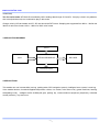
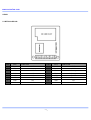
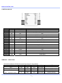
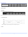
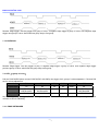
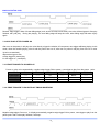
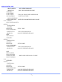
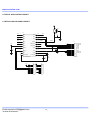
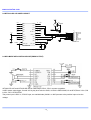
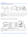
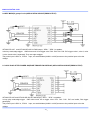
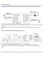
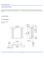
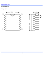
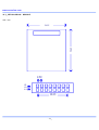
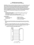
www.emartee.com
WTV020-SD MODULE
WTV020-SD-20S and WTV020-SD-16P
1.PRODUCT FEATURES ..................................................................................................................................................... 2
3.APPLICATION DIAGRAM .................................................................................................................................................. 3
4.APPLICATIONS ................................................................................................................................................................. 3
5.PINS .................................................................................................................................................................................. 4
5.1.WTV020-SD-20S ..................................................................................................................................................... 4
5.2.WTV020-SD-16P ..................................................................................................................................................... 5
6.MODULE SELECTION .................................................................................................................................................... 5
7.CONTROL MODES ........................................................................................................................................................... 6
7.1.MP3 MODE.............................................................................................................................................................. 6
7.1.1. ON/OFF(PALY/STOP) .................................................................................................................................. 6
7.1.2.NEXT ............................................................................................................................................................. 6
7.1.3.PREVIOUS .................................................................................................................................................... 7
7.2. KEY(3 group of voice) ........................................................................................................................................ 7
7.2.1. EDGE RETRIGGER ..................................................................................................................................... 7
7.3.KEY(5 group of voice) .............................................................................................................................................. 8
7.3.1. All KEYS ARE EDGE RETRIGGER .............................................................................................................. 8
7.3.2.EDGE RETRIGGER TIMING WAVEFORM ................................................................................................... 8
7.3.3.ALL KEYS ARE ON/OFF(unloop) .................................................................................................................. 9
7.3.4. ALL KEYS ARE ON/OFF(unloop) TIMING WAVEFORM .............................................................................. 9
7.3.5. ALL EKYS ARE ON/OFF(loop) ................................................................................................................ 9
7.3.6. ON/OFF(loop) TIMING WAVEFORM ............................................................................................................ 9
7.4.LOOP PLAY AFTER POWER ON .......................................................................................................................... 10
7.4.1.EDGE TRIGGER TO PAUSE/PLAY ............................................................................................................. 10
7.4.2. EDGE TIRGGER TO PAUSE/PLAY TIMING WAVEFORM ......................................................................... 10
7.4.3.LEVEL TRIGGER TO PAUSE/PLAY ............................................................................................................ 11
7.4.4.LEVEL TRIGGER TO PAUSE/PLAY TIMING WAVEFORM ......................................................................... 11
7.5.TWO LINE SERIAL MODE .................................................................................................................................... 11
7.5.1、I/O FUNCTION IN TWO LINE SERIAL MODE .......................................................................................... 11
7.5.2. VOICE ADDRESSES.................................................................................................................................. 11
7.5.3.TIMING WAVEFORM IN TWO LINE SERIAL MODE .................................................................................. 12
7.5.4. CODE DESCRIPTIONS ............................................................................................................................. 12
7.5.5. PROGRAM EXAMPLE ............................................................................................................................... 13
8.TYPICAL APPLICATION CIRCUIT .................................................................................................................................. 18
8.1.WTV020-SD-20S INNER CIRCUIT ....................................................................................................................... 18
8.2.WTV020-SD-16P INNER CIRCUIT........................................................................................................................ 19
8.3.MP3 MODE APPLICATION CIRCUIT(PWM OUTPUT) ......................................................................................... 19
8.4.MP3 MODE APPLICATION CIRCUIT(DAC OUTPUT) .......................................................................................... 20
8.5.KEY MODE(3 group of voice) APPLICATION CIRCUIT(PWM OUTPUT) .............................................................. 20
- 1-
www.emartee.com
8.6.KEY MODE(5 group of voice)APPLICATION CIRCUIT(PWM OUTPUT) .............................................................. 21
8.7.LOOP PLAY AFTER POWER ON(EDGE TIRGGER PAUSE/PLAY) APPLICATION CIRCUIT(PWM OUTPUT) ... 21
8.8.LOOP PLAY AFTER POWER ON (LEVEL TRIGGER PAUSE/PLAY)APPLICATION CIRCUIT(PWM OUTPUT) .. 22
8.9.TWO LINE SERIAL MODE APPLICATION (PWM OUTPUT) ........................................................................... 22
9.VOICE FILES IN SD CARD ............................................................................................................................................. 23
10. PACKAGE SIZE ............................................................................................................................................................ 23
10.1.WTV020SD-20S .................................................................................................................................................. 23
10.2.WTV020-SD-16P ................................................................................................................................................. 24
10.3、WTV020-SD-20S MODULE ............................................................................................................................ 25
11.SUPPLY INFORMATION................................................................................................................................................ 26
12.VERSIONS .................................................................................................................................................................... 26
1.PRODUCT FEATURES
◎Support 1GB SD card max. or SPI flash 64MB max.
◎Support 4 Bit ADCPM format files.
◎Sampling rate from 6kHZ to 36KHZ for AD4 voice format.
◎Sampling rate from 6KHz~16KHz for WAV voice format
◎16 Bit DAC / PWM audio output.
◎Key mode,MP3 mode and two line serial mode are optional .Can choose one of them
◎Copy voice files to SD card by PC.
◎Working voltage: DC2.7~3.5V
◎Quiescent current:: 3uA
2.SUMMARIZE
This module with MP3 mode, key mode(control 3 group of voice with volume adjustment or 5group of voice), two line
serial mode, and Loop play mode(after power on ,the module will play loop, with memory function in the mode) They are
optional. Customers can choose one of the modes in a module. Also can be customized.
MP3 mode: With play/stop, next , previous, vol+,vol- functions
Key mode(3 group of voice): One key trigger one group of voice,and with vol-, and vol+ .
are edge retrigger
all keys’ default trigger modes
Key mode(5 group of voice): One key trigger one group of voice, trigger mode can be follows: 1. All keys are edge
retrigger.
2.All keys are ON/OFF (voice will not cycle after finished)
3.All keys are ON/OFF(voice will cycle after
finished)
Loop play mode: After power on , it will play the voices automatically . it doesn’t need to tirgger the I/O . and with memory
function(when you playing voice 2, power was cut off,next time power on it will start from voice 2 or voice 3 .(Can be
- 2-
www.emartee.com
customized)
Two line serial mode: WTV020-SD controlled by MCU sending data through CLK and DI . Can play voices in any address,
also voices(include mute) can combined to play in this mode.
Change voice by SD card reader and PC. SD card should be FAT format. Sampling rate supported from 6KHz~32KHz and
36KHz for ad4 voice format. 6KHz~16KHz for WAV voice format.
3.APPLICATION DIAGRAM
BUSY
PINS
WTV020-SD MODULE
SD CARD
AUDIO OUTPUT
4.APPLICATIONS
This module can use in automobile( car bug, parking radar, GPS navigation system), Intelligent home system, house bug,
Voice medical devices, household appliances(induction cooker, rice cooker, micro-wave oven), game machines, learning
tools(talking book), Intelligent traffic facilities(toll gate, parking lot), communications equipment( telephone), industrial
control( elevator ), toys and so on.
- 3-
www.emartee.com
5.PINS
5.1.WTV020-SD-20S
PIN
SYS.
1
DC+3.3V
2
FUNCTION
PIN
SYS.
+3.3V
9
GND
GND
SPK+
Audio output
10
DC+3.3V
+3.3V
3
P07
I/O
11
SPK+
Audio output
4
P03
I/O
12
SPK-
Audio output
5
NC
NC
13
P06
BUSY
6
NC
NC
14
RST
Reset
7
P02
I/O
15
P04
I/O
8
NC
NC
16
P05
I/O
- 4-
FUNCTION
www.emartee.com
5.2.WTV020-SD-16P
1
2
3
4
5
6
7
8
RESET
AUDIO-L
NC
SPK+
SPKNC
P04
GND
16
15
14
13
12
11
10
9
VDD
P06
NC
P02
P03
NC
P05
P07
PIN
SYS.
DESCRIPTION
FUNCTION
1
RESET
RESET
Reset pin
2
AUDIO-L
DAC+
3
NC
NC
4
SP+
PWM+
5
SP-
PWM-
PWM audio output to speaker
6
NC
NC
NC
7
P04
K3/A2/CLK
Key /CLK in two line serial
8
GND
GND
Address pin
9
P07
K5/A4/SBT
Key
10
P05
K4/A3/DI
Key /DI in two line serial
11
NC
NC
NC
12
P03
K2/A1
Key
13
P02
K1/A0
Key
14
NC
NC
NC
15
P06
BUSY
BUSY pin
16
VDD
VDD
Power input
6.MODULE
DAC audio output(+) to amplifier
NC
PWM audio output to speaker
SELECTION
WTV020-SD-20S and WTV020-SD-16P are the same but chip package.
MODE
VOICES
TRIGGER
BUSY
AUDIO
MP3
256
KEY
YES
DAC/PWM
KEY(3 group of voice)
3
KEY
YES
DAC/PWM
EDGE IRRETRIGGER
5
KEY
YES
DAC/PWM
EDGE RETRIGGER
5
KEY
YES
DAC/PWM
ON/OFF(unloop)
KEY(5 group of voice)
- 5-
NOTE
www.emartee.com
LOOP PLAY(after power on)
TWO LINE SERIAL
5
KEY
YES
DAC/PWM
ON/OFF(loop)
256
KEY
YES
DAC/PWM
ON/OFF(edge)
256
KEY
YES
DAC/PWM
ON/OFF(level)
256
BY MCU
YES
DAC/PWM
7.CONTROL MODES
7.1.MP3 MODE
In the MP3 mode, WTV020-SD module default with 6 I/Os
I/O
P02
P03
P04
P05
P06
P07
FUNCTION
K1
K2
K3
K4
BUSY
K5
TRIGGER
NEXT
PREVIOUS
VOL+
VOL-
------
ON/OFF
BUSY is for signal output test , when the playing voice, BUSY output is high level, can connect to LED for indicating.
7.1.1. ON/OFF(PALY/STOP)
Remark: Edge trigger. A negative edge trigger to play, next negative edge to stop.
7.1.2.NEXT
- 6-
www.emartee.com
Remark: Edge trigger. One key trigger one group of voice. A negative edge trigger a group of voice, next negative edge
trigger next group of voice, after finish last group loop to first group.
7.1.3.PREVIOUS
Remark: Edge trigger. One key trigger to play. A negative edge trigger a group of voice, next negative edge trigger
previous group of voice, after finish first group loop to last group.
7.2. KEY(3 group of voice)
Pull low P02/P03/P07(short connect P02/P03/P07 with GND) can trigger the 3 group of voices separated , P04 and P05
are for volume adjustment.
I/O
P02
P03
P04
P05
P06
P07
FUNCTION
K1
K2
K3
K4
BUSY
K5
TRIGGER
EDGE
IRRTRIGGER
EDGE
IRRTRIGGER
VOL+
VOL-
-----
EDGE
IRRTRIGGER
VOICE
GROUP 1
GROUP 2
-----
-----
-----
GROUP 3
Key K1~K3 are edge retrigger , BUSY is for signal output test , when the playing voice, BUSY output is high level, can
connect to LED for indicating.
7.2.1. EDGE RETRIGGER
- 7-
www.emartee.com
Remark: Edge trigger. When I/O test falling edge( such as this I/O short touch GND) ,the voice will be triggered. During the
playing , the next falling edge will not interrupt the voice,after voice play finished,falling edge will make it replay .
7.3.KEY(5 group of voice)
One button trigger one voice , total 5 group of voice , during playing BUSY output is high level, can connect LED to indicate
it .
Three optional trigger mode:
a.All keys are edge retrigger
b.All keys are ON/OFF(unloop)
c.All keys are ON/OFF(loop)
7.3.1. All KEYS ARE EDGE RETRIGGER
I/O
P02
P03
P04
P05
P06
P07
FUNCTION
K1
K2
K3
K4
BUSY
K5
TRIGGER
EDGE
RETRIGGER
EDGE
RETRIGGE
R
EDGE
RETRIGGER
EDGE
RETRIGGER
-----
EDGE
RETRIGGER
VOICE
GROUP 1
GROUP 2
GROUP 3
GROUP 4
-----
GROUP 5
7.3.2.EDGE RETRIGGER TIMING WAVEFORM
Remark: Edge trigger. When I/O test falling edge( such as this I/O short touch GND) ,the voice will be triggered. During the
playing , the next falling edge will interrupt the voice and replay from beginning.
- 8-
www.emartee.com
7.3.3.ALL KEYS ARE ON/OFF(unloop)
Trigger I/O(short connect to GND) can play voice ,next trigger make it stop. After voice play finished, it will stop .
I/O
P02
P03
P04
P05
P06
P07
FUNCTION
K1
K2
K3
K4
BUSY
K5
TRIGGER
ON/OFF
ON/OFF
ON/OFF
ON/OFF
-----
ON/OFF
GROUP 1
GROUP 2
GROUP 3
GROUP 4
-----
GROUP 5
VOICE
7.3.4. ALL KEYS ARE ON/OFF(unloop) TIMING WAVEFORM
Remark: Edge trigger. When I/O test falling edge( such as this I/O short touch GND) ,the voice will be triggered. After play
finished, will stop . During the playing , the next falling edge will stop the voice ,other falling edge will make it play again.
7.3.5. ALL EKYS ARE ON/OFF(loop)
Trigger I/O(short connect to GND) can play voice ,next trigger make it stop. After voice play finished, it will loop .
I/O
P02
P03
P04
P05
P06
P07
K1
K2
K3
K4
BUSY
K5
TRIGGER
ON/OFF
ON/OFF
ON/OFF
ON/OFF
-----
ON/OFF
VOICE
GROUP 1
GROUP 2
GROUP 3
GROUP 4
-----
GROUP 5
FUNCTION
7.3.6. ON/OFF(loop) TIMING WAVEFORM
- 9-
www.emartee.com
Remark: Edge trigger. When I/O test falling edge( such as this I/O short touch GND) ,the voice will be triggered. After play
finished, will cycle play. During the playing , the next falling edge will stop the voice ,other falling edge will make it play
again
7.4.LOOP PLAY AFTER POWER ON
After turn on the power, it will play the voice directly, trigger the relative I/O can pause, next trigger will keep playing.In this
mode, when the module playing voice 2 and the power was cut off, after turn on power it will play from voice 2 or voice
3(can be customized)
Alternative trigger mode:
a.Edge tirgger to pause /play
b.Level trigger to pause/play
7.4.1.EDGE TRIGGER TO PAUSE/PLAY
Power on, play voice automatically, negative edge tirgger P04 to pause , next trigger to play from the pause
I/O
P02
P03
P04
P05
P06
P07
FUNCTION
------
------
K1
------
BUSY
------
TRIGGER
------
------
PAUSE/PLAY
------
-----
------
VOICE
------
------
ALL VOICE
------
-----
------
point.
7.4.2. EDGE TIRGGER TO PAUSE/PLAY TIMING WAVEFORM
Negative edge trigger. Power on , it will play automatically, negative edge trigger P04 to pause , next tirgger to play from the
pause point. After voices play finished, it will loop .
- 10-
www.emartee.com
7.4.3.LEVEL TRIGGER TO PAUSE/PLAY
Power on , it will play automatically , Low level to trigger P05 to pause, next trigger to play from the pause point.
I/O
P02
P03
P04
P05
P06
P07
FUNCTION
------
------
------
K1
BUSY
------
TRIGGER
------
------
------
PAUSE/PLAY
------
------
VOICE
------
------
------
ALL VOICE
------
------
7.4.4.LEVEL TRIGGER TO PAUSE/PLAY TIMING WAVEFORM
Negative level trigger. Power on , it will play automatically, negative level trigger P05 to pause , next tirgger to play from the
pause point. After voices play finished, it will loop .
7.5.TWO LINE SERIAL MODE
In the two line serial mode ,there are two communication port, they are CLK and DI. In addition, there is a reset port, 1
second after reset , if no action to the module, the chip will be into standby status within one second if no action after reset.
7.5.1、I/O FUNCTION IN TWO LINE SERIAL MODE
I/O
P02
P03
P04
P05
P06
P07
FUNCTION
K1
K2
CLK
DI
BUSY
K3
TRIGGER
NEXT
PREVIOUS
------
PALY/STOP
7.5.2. VOICE ADDRESSES
- 11-
www.emartee.com
512 group of voice can be loaded in SD card. The voice file name are decimal , such as 0000.ad4, 0001.ad4, ……When
the MCU send data to trigger, the data should be binary data corresponding to voice file name. MCU send signal to CLK
and ID at the same time. DI data send high first, then low. When there is no data, CLK and DI are high level.
ADDRESSES
TRIGGER STATE
FILE NAME(.ad4)
TRIGGER DATA(BINARY)
th
ADDR 1
PLAY 1 GROUP VOICE
ADDR 2
0000
0000000000000000
nd
0001
0000000000000001
rd
0002
0000000000000010
th
0003
0000000000000011
2
ADDR 3
3
ADDR 4
4
……
……
……
……
th
0508
0000000111111100
th
0509
0000000111111101
th
0510
0000000111111110
th
0511
0000000111111111
ADDR 509
509
ADDR 510
510
ADDR 511
511
ADDR 512
512
7.5.3.TIMING WAVEFORM IN TWO LINE SERIAL MODE
RESET
5mS
300mS
CLK
2mS
200uS
DATA
BUSY
VOICE
7.5.4. CODE DESCRIPTIONS
CODE
FUNCTION
DESCRIPTION
VOICE VOLUME
THE VOLUME CAN BE ADJUSTED DURING PLAY OR STAND BY
ADJUSTMENT
STATUS. FFF0H IS MIN, FFF7H IS MAX, TOTAL 8 LEVEL .
FFFEH
PALY/PAUSE
PLAY/PAUSE THE VOICE IN THE ADDRESS
FFFFH
STOP
FFF0H~FFF7H
STOP TO PLAY THE VOICE
The default volume is maximum. FFF0H is mute. Volume can be adjusted in play or stop status.
- 12-
www.emartee.com
7.5.5. PROGRAM EXAMPLE
ORG 0000H
KEY EQU P1.1
; KEY PIN
KEY2 EQU P1.2
;VOLUME
KEY3 EQU P1.3
; CLK+
KEY4 EQU P1.6
;CLKKEY5 EQU P1.7
;TRANSMIT VOLUME,THEN ADDRESS
LED EQU P3.0
;SHOW KEY PRESSED
SCL EQU P3.2
;CLK PIN
SDA EQU P3.3
;DATA PIN
RST EQU P3.4
;RESET PIN
DAIFAZHI EQU 50H
;SEND CODE VALUE TEMP
VOICENUM EQU 51H
;VOLUME
CLKNUM EQU 52H
;CLK
MOV DAIFAZHI,#0H
;INITIAL SEND VALUE 0
MOV VOICENUM,#0F0H ; VOLUME INITIAL VALUE F0H
MOV CLKNUM,#2
; DEFAULT SEND CODE 1MS
MOV R5,#8
; LOOP EIGHT TIMES
SETB SCL
SETB SDA
SETB RST
MAIN:
JB KEY,KEY22
CLR LED
MOV R6,#5
; DELAY 10MS
LCALL DELAY2MS
JB KEY,KEY22
; KEY PRESS DEBOUNCE
JNB KEY,$
;WAIT KEY PRESSED RELEASE
SETB LED
LCALL RESET
LCALL TWO_LINE
;TWO LINE SEND CODE SUBPROGRAM
INC DAIFAZHI
;CODE VALUE ADD 1
MOV A,DAIFAZHI
CJNE A,#37,XX2
;WHETHER VOLUME REACH MAX. VALUE 128
XX2: JC KEY22
MOV DAIFAZHI,#0H
KEY22:
JB KEY2,KEY33
CLR LED
MOV R6,#5
;DELAY 10MS
LCALL DELAY2MS
- 13-
www.emartee.com
JB KEY2,KEY33
;KEY PRESS DEBOUNCE
JNB KEY2,$
;WAIT KEY PRESSED RELEASE
SETB LED
LCALL RESET
LCALL VOICE
;TWO LINE SEND CODE SUBPROGRAM
INC VOICENUM
;CODE VALUE ADD 1
MOV A,VOICENUM
CJNE A,#0F8H,XX4
;WHETHER VOLUME REACH MAX. VALUE
XX4: JC KEY33
MOV VOICENUM,#0F0H
KEY33:
JB KEY3,KEY44
CLR LED
MOV R6,#5
;DELAY 10MS
LCALL DELAY2MS
JB KEY3,KEY44
; KEY PRESS DEBOUNCE
JNB KEY3,$
;WAIT KEY PRESSED RELEASE
NOP
INC CLKNUM
SETB LED
KEY44:
JB KEY4,KEY55
CLR LED
MOV R6,#5
; DELAY 10MS
LCALL DELAY2MS
JB KEY4,KEY55
; KEY PRESS DEBOUNCE
JNB KEY4,$
;WAIT KEY PRESSED RELEASE
NOP
DEC CLKNUM
MOV A,CLKNUM
CJNE A,#0H,XX5
MOV CLKNUM,#1
; SEND CODE KEEP 100US AT LEAST
XX5:
SETB LED
KEY55:
JB KEY5,MAIN
CLR LED
MOV R6,#5
LCALL DELAY2MS
JB KEY5,XX6
JNB KEY5,$
; DELAY 10MS
;WAIT KEY PRESSED RELEASE
;WAIT KEY PRESSED RELEASE
- 14-
www.emartee.com
LCALL RESET
MOV VOICENUM,#0F6H
LCALL VOICE
LCALL TWO_LINE
XX6:
LJMP MAIN
TWO_LINE:
;///VOICE ADDRESS SEND CODE SUBPROGRAM
CLR SCL
MOV R6,#2
LCALL DELAY1MS
MOV A,#0
LOOP1:
CLR SCL
RLC A
MOV SDA,C
MOV R6,CLKNUM
LCALL DELAY50US
SETB SCL
MOV R6,CLKNUM
LCALL DELAY50US
DJNZ R5,LOOP1
MOV R5,#08H
MOV A,DAIFAZHI
LOOP2:
CLR SCL
RLC A
MOV SDA,C
MOV R6,CLKNUM
LCALL DELAY50US
SETB SCL
MOV R6,CLKNUM
LCALL DELAY50US
DJNZ R5,LOOP2
MOV R5,#08H
RET
VOICE:
;////VOLUME VALUE SEND CODE SUBPROGRAM
CLR SCL
MOV R6,#2
LCALL DELAY1MS
MOV A,#0FFH
LOOP3:
- 15-
www.emartee.com
CLR SCL
RLC A
MOV SDA,C
MOV R6,CLKNUM
LCALL DELAY50US
SETB SCL
MOV R6,CLKNUM
LCALL DELAY50US
DJNZ R5,LOOP3
MOV R5,#08H
MOV A,VOICENUM
LOOP4:
CLR SCL
RLC A
MOV SDA,C
MOV R6,CLKNUM
LCALL DELAY50US
SETB SCL
MOV R6,CLKNUM
LCALL DELAY50US
DJNZ R5,LOOP4
MOV R5,#08H
RET
RESET:
CLR RST
MOV R6,#3
LCALL DELAY1MS
SETB RST
MOV R6,#130
LCALL DELAY2MS
RET
DELAY2MS:
;DELAY 2MS SUBPROGRAM, CHANGE R6 VALUE CAN CHANGE DELAY TIME
L1:
MOV R7,#248
L2:
NOP
NOP
NOP
NOP
NOP
NOP
DJNZ R7,L2
DJNZ R6,L1
RET
- 16-
www.emartee.com
DELAY50US:
; DELAY 25UM SUBPROGRAM, CHANGE R4 VALUE CAN CHANGE DELAY TIME
L11: MOV R7,#6
L22:
NOP
NOP
DJNZ R7,L22
DJNZ R6,L11
RET
DELAY1MS:
; DELAY 1MS SUBPROGRAM, CHANGE R6 VALUE CAN CHANGE DELAY TIME
L31:
L32:
MOV R7,#240
NOP
NOP
DJNZ R7,L32
DJNZ R6,L31
RET
END
Email:[email protected]
Tel:0086-20-85638557
- 17-
www.emartee.com
8.TYPICAL APPLICATION CIRCUIT
8.1.WTV020-SD-20S INNER CIRCUIT
3.3V
Q1
U1
P03
1
P04
2
P05
3
P06
4
P07
5
3.3V
6
7
C2
104
8
9
10
P03
P02
P04
P01
P05
P00
P06
REST
P07
OSCO/P11
VCC
19
VDD
SPK_N
VPP
NC
17
RESET
16
P11
15
P10
RESET
J1
P00
P01
3.3V
14
C4
P10
104
12
11
PAD_EQI
WTV020SD-20S
C3
102
3.3V
J2
GND
SPK2
SPK1
P06
REST
P04
P05
Email:[email protected]
Tel:0086-20-85638557
1
2
3
4
5
6
7
8
+3.3V
P11
13
GND
PAD_EQO
104
18
OSCI/P10
SPK_P
809
C1
P02
20
3.3V
SPK2
P07
P03
P02
J3
1
2
3
4
5
6
7
8
- 18-
R6
15K
1
2
3
4
5
6
7
8
9
10
11
SD DAT2
SD DAT3
CMD
VSS
VDD
CLK
VSS
SD DAT0
SD DAT1
SD Card
www.emartee.com
8.2.WTV020-SD-16P INNER CIRCUIT
+3.3V
P03
1
P04
2
P05
3
P06
4
P07
5
+3.3V
6
SP+ 7
C2
SP-
8
104
9
AUDIO-L 10
P03
P02
P04
P01
P05
P00
P06
REST
P07
OSCO/P11
VCC
OSCI/P10
SPK_P
VDD
SPK_N
VPP
NC
PAD_EQO
WTV020SD-20S
GND
PAD_EQI
20
Q1
AME8500
P02
19
18
C1 104
17
RESET
16
P11
15
P10
RESET
J1
+3.3V
14
R7 150
13
12
P00
P01
3.3V
P11
P10
1
2
3
4
5
6
7
8
SD DATA2
SD DATA3
CMD
VDD
CLK
VSS
SD DATA0
SD DATA1
Micro SD Card
11
C3
102
R6
15K
8.3.MP3 MODE APPLICATION CIRCUIT(PWM OUTPUT)
WTV020-SD-16P and WTV020-SD-20S,In PWM output, SPK+ ,SPK- connect to speaker .
In MP3 mode, edge trigger. Control I/Os by key short touch to GND, I/O P02 is PREVIOUS,P03 is NEXT,P04 is VOL+,P05
is VOL-,P07 is PLAY/STOP.
The power input is DC3.3v, if DC5V input, two serial diodes (IN4001 or 4007)connect to the positive input to low the
voltage.
- 19-
www.emartee.com
8.4.MP3 MODE APPLICATION CIRCUIT(DAC OUTPUT)
WTV020-SD-16P DAC output,” Audio L” and module GND to amplifier. WTV020-SD-20S DAC output, “SPK+” and module
GND to amplifier.
In MP3 mode, edge trigger. Control I/Os by key short touch to GND, I/O P02 is PREVIOUS,P03 is NEXT,P04 is VOL+,P05
is VOL-,P07 is PLAY/STOP.
The power input is DC3.3v, if DC5V input, two serial diodes (IN4001 or 4007)connect to the positive input to low the
voltage.
8.5.KEY MODE(3 group of voice) APPLICATION CIRCUIT(PWM OUTPUT)
WTV020-SD-16P and WTV020-SD-20S in PWM output, “SPK+” ,”SPK-” to speaker .
In the key mode,edge trigger. GND short touch I/O to trigger voice. P02、P03、P04、P05、P07 trigger voice 1,voice 2,
vol+,vol-,and voice 3 separately.
The power input is DC3.3v, if DC5V input, two serial diodes (IN4001 or 4007)connect to the positive input to low the
voltage.
- 20-
www.emartee.com
8.6.KEY MODE(5 group of voice)APPLICATION CIRCUIT(PWM OUTPUT)
WTV020-SD-16P and WTV020-SD-20S in PWM output, “SPK+” ,”SPK-” to speaker .
In the key mode,edge trigger. GND short touch I/O to trigger voice. P02、P03、P04、P05、P07 trigger voice 1,voice 2, voice
3,voice 4,and voice 5 separately. They are edge retrigger.
The power input is DC3.3v, if DC5v input, two serial diodes (IN4001 or 4007)connect to the positive input to low the
voltage.
8.7.LOOP PLAY AFTER POWER ON(EDGE TIRGGER PAUSE/PLAY) APPLICATION CIRCUIT(PWM OUTPUT)
WTV020-SD-16P and WTV020-SD-20S in PWM output, “SPK+” ,”SPK-” to speaker .
In loop play mode,edge trigger. GND short touch I/O to trigger voice. P02、P03、P05、P07 are invalid, P04 trigger
pause/play.
The power input is DC3.3v, if DC5v input, two serial diodes (IN4001 or 4007)connect to the positive input to low the
voltage.
- 21-
www.emartee.com
8.8.LOOP PLAY AFTER POWER ON (LEVEL TRIGGER PAUSE/PLAY)APPLICATION CIRCUIT(PWM OUTPUT)
WTV020-SD-16P and WTV020-SD-20S in PWM output, “SPK+” ,”SPK-” to speaker .
In loop play mode,edge trigger. GND short touch I/O to trigger voice. P02、P03、P04、P07 are invalid, P05 trigger
pause/play.
The power input is DC3.3v, if DC5V input, two serial diodes (IN4001 or 4007)connect to the positive input to low the
voltage.
8.9.TWO LINE SERIAL MODE APPLICATION (PWM OUTPUT)
WTV020-SD-16P and WTV020-SD-20S in PWM output, “SPK+” ,”SPK-” to speaker .
In the two line serial mode, edge tirgger. MCU control I/O, P02 is next, P03 is previous, P07 is pause/play.
The power input is DC3.3v, if DC5V input, two serial diodes (IN4001 or 4007)connect to the positive input to low the
voltage.
- 22-
www.emartee.com
9.VOICE FILES IN SD CARD
Load voice files to SD card, and rename the files in this way, for WAV format voice :0000.wav , 0001.wav, 0002.wav……,
for ad4 format voice: 0000.ad4, 0001.ad4,0002.ad4 ……., 512 files max. In MP3 mode and Loop play mode, voice will play
in order.
10. PACKAGE SIZE
10.1.WTV020SD-20S
PACKAGE:SOP20
Unit:mm
- 23-
www.emartee.com
10.2.WTV020-SD-16P
Package:DIP16
Unit:mm
17.40
#1
9.32
4.25
#16
20.60
2.36
#8
#9
- 24-
www.emartee.com
10.3、WTV020-SD-20S
MODULE
Unit:mm
50.69
36.55
2.59
2.59
18.13
- 25-
www.emartee.com
11.SUPPLY INFORMATION
In order to save customers production cost ,and good looking, we are not only sell modules, also we can sell the chips on
the module.customers can make it on their circuit board.
ITEM
PICTURE
WTV020-SD-16P
WTV020-SD-20S
WTV020SD-20S
(above two modules use this chip)
12.VERSIONS
VERSION
DATE
DESCRIPTION
V1.3
2008-11-19
ORIGINAL
- 26-