1
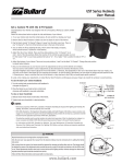
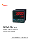
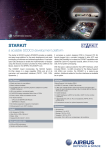
Multi-function
Control keyboard
USERS’ MANUAL
YSS-01CK
V3.0
2
Thanks for your purchase of our product.
l In order to make good use of this product, please read this user ’s manual carefully.
l In order to use this product correctly and safely; be familiar with all operation steps.
l Please keep this user’s manual for future reference.
l The information contained in this document is subject to changes without notice.
SAFETY WARNING
n
n
n
n
n
In case of failure, be sure to turn off the power or remove the power supply
before contacting service personnel.
To avoid electric shocks, do not disassemble this product on your own. Be sure
to ask a skilled technician for the job.
The power of this product is DC12V/1.2A. Do not use other types of power
supply, or the product may be destroyed or fire can be triggered.
Keep unconnected wires, plugs duly insulated, or they might cause short
circuit and damage this product.
Do NOT connect power to the unit until all installation steps are completed.
3
Table of Contents
Safety warning
3
Introduction
5
Use instructions
Accessories
5
Front-panel
6
Rear connects line
8
System integration diagram.
9
Instruction of operation.
10
Remarks
Maintenance & cleaning.
14
Troubleshooting.
14
Optional accessories.
15
4
Introduction
This product utilizes the most advanced communication protocol.
the full series of CCTV products produced by SEEKU.
can effectively improve system efficiency.
read.
It can integrate
The powerful control functions
Large LCD screen make messages easy to
Attached with multi directional variable speed joystick makes control operation
easier.
Accessories
1. Multi function control keyboard
2. RS-485 control connection wiring
3. Power supply
4. User manual
5
Front panel
※
Keys without a description are not operational in this model.
1.
Camera selection key.
2.
P o w e r L ED
3.
No f u nct i on
4.
LC D
5.
Pr ese t p o in t Call, S a v e a nd Eras e
6.
Set up auto pan to the left
7.
Set up auto pan to the right
8.
A u t o P a n L ED
9.
Ex ecu te A u t o Pa n, Ex ecu t e gro u p a ut o cr u is e, Se t d well t im e
an d cru is e s p ee d f or g r ou p a ut o cru is e
10 . Call a l arm recor d u p Û
11 . Call a l arm recor d d o w n Ü
6
12 . O u t p u t s witch ON /OF F
13 . A la r m ON/OF F
14. Num ber k e y
15 . E n t e r k e y
16 . No f u nct i on
17 . K e yb o ard s ys t e m set u p
18 . E SC k e y
19 . O S D m an u al, esc k e y
20 . O S D m an u al, Tilt left downÙÜ
21 . O S D m an u al, e nt er k e y
22 . O S D m an u al, tilt right downÚÜ
23 . Star lig ht n i gh t v is i o n a d j ustm en t
24 . Foc us
25 . zo om
26 . J o ys t ic k
7
Rear connects line
27 . P o w e r s u pp l y D C12V
28. RS-232 c om m unic a tio n c o nn ect i o n s ock et 6 P 6C
(no t s u pp or te d by t h is m o d e l)
29 . RS-485 c om m unic a tio n c o nn ect i o n s ock et 6 P 6C
Pin
1
2
3
4
5
6
8
RS-232
X
GND
TxD
RxD
X
X
RS-485
X
X
DD+
X
X
System integration diagram
9
Operation instruction
1. Selection of Camera ID.
Cam: 001
Press CAM key once and enter the camera ID
Choose Cam ID: _ _ _
selection mode, input camera ID 001 ~ 255,
press ENT key to enter.
Ex: CAM →
002 →
ENT
2. Direction control
Joystick may control 8 directions; Rotation speed can
be variable by controlling a joystick.
3. Lens control
Cam: 001
*** Zoom Out ****
Choose Cam ID:001
Press down FOCUS NEAR / FAR or ZOOM IN / OUT
for manual adjustment.
4. Preset position Call, Save, and Clear
ENT
Input camera ID→
OK !
Cam: 001
Call preset position:
Press PRESET once →
Cam: 001
*** Right-Up ****
Choose Cam ID: 001
OK !
Call Preset No: ___
Save preset point:
Press PRESET twice →
Input camera ID
→
ENT
Clear preset point:
Press PRESET three times → Input camera ID→
ENT
※ You can set up 128 preset position, every 32 preset for one group
group 1: 1 ~ 32 /Group 2: 33 ~ 64 /Group 3: 65 ~ 96 /Group 4: 97 ~ 128
5. Pan Limit set up
Pan limit to the left set up : move the camera to pan
Cam: 001
limit to the left ,press MISC1 →
Save limit Start ?
ENT
Pan limit to the right set up : move the camera to pan
limit to the right ,press, MISC2 →
ENT
10
6. Execute Auto pan, group auto cruise, auto pan speed set up,
Dwell time set up
Cam: 001
Execute auto pan:
Set Auto Pan ?
AUTO PAN press down 1 time →
ENT
Execute group auto cruise:
AUTO PAN press down 2 times →
1~5 →
ENT
Cruise speed set up: AUTO PAN press down 3 times →
Dwell time set up: AUTO PAN press down 4 times →
※
1~6 →
00 ~ 99 →
ENT
ENT
Group auto cruise 1 ~ 5 :
1Group auto cruise 1: preset
1 ~ 32
2 Group auto cruise 2: preset 33 ~ 64
3Group auto cruise 3: preset 65 ~ 96
4 Group auto cruise 4: preset 97 ~ 128
5Group auto cruise 5: preset
1 ~ 128
※ Set up cruise speed 1 ~ 6 : (means the approximated movement speed for each second)
1 10 ゚ /sec 2 20 ゚ /sec
3 30 ゚ /sec 4 40 ゚ /sec 5 50 ゚ /sec 6 60 ゚ /sec
※ Set up dwell time 0 ~ 99 : Second
Input 15
means the dwell time is approximately 15 seconds.
7. Camera OSD manual operation
Camera set up, the set up keys on the front panel
(19 ~ 22)
p
q
t
u
u
Enter OSD manual / enter
p
Up/ri g ht
q
Down/l e ft
t
Ret ur n /E S C
Cam: 001
Camera OSD Key : Ent
※ Under the contro l of keyboa rd , Protocol cannot be changed.
11
8. Alarm set up
(DI)
Cam: 001
Alarm ON set up:
Press F1 once →
E n a b l e A l a r m N o: _ _
ENT
1~ 10 →
Alarm OFF set up:
Press F1 twice →
ENT
1 ~ 10 →
※ Alarm 1 ~ 10 correspond to preset position 1 ~ 10
※ when alarm is triggered, there will be warning siren. Other than the numerical
keys and lens control keys, press any key can stop the warning siren.
9. Output on/off set up (DO)
Cam: 001
Camera out put ON set up:
Press F2 once→
Open Aux No :
ENT
1~8 →
_
Camera out put OFF set up:
Press F2 twice →
1 ~ 8→
ENT
10. Inquiry of alarm record
Cam: 001
Inquiry of previous record: F3
Inquiry of previous record: F4
12: B-001 AL 1 2
※ May record the latest 80 alarm information
※ Display description:
No Any Alarm List, No record of alarm been triggered
12:A-001 AL 2, Means the alarm collector 1 point 2 triggered
13:A-001 AL Reset, Means alarm collector 1 all reset
14:B-001 AL 1 2, Means the camera’s alarm1 and 2 triggered
15:B-001 AL Reset, Means camera’s alarm reset
12: B-001 AL 1 2
Alarm no.
Alarm machine ID.
Equipment type: A-alarm collector / B-camera
Alarm status sequence
12
11. Keyboard system set up
*** System Setup ***
>Clear Alarm List?
SHIFT + CAM enter set up manual
Use the OSD key
p
q
to select the required
> S u r e ? 0: Yes 1: No
set up items
press down
u
and enter set up mode >Sure? 0: Yes 1: No
Enter 0 (confirm change) or 1 (no change), and return to previous layer
Press down
t
/ ESC to return to previous /ESC
※ Set up item:
>Clear Alarm List? Clear alarm record
>Set Keypad Master? Set up keyboard as the main control keyboard (needs to be
set up when there are two or more keyboards)
>Set Keypad Slave?
Set up keyboard as auxiliary control keyboard ((needs to
be set up when there are two or more keyboards)
13
Maintenance & cleaning
n Prevent water or other materials fall into the keyboard and cause control
abnormal or malfunction.
n Daily cleaning
Use soft cloth to wipe clean.
n Removal of stubborn stains
The surface of the keyboard is difficult to clean with dry cloth. It can be wiped
clean with soft cloth with dilute neutral detergents and then wipe clean with soft
dry clothe.
※ Detergent on the soft cloth shall not penetrate into the gaps between the keys.
n Do not use benzene, diluents or gasoline and other corrosive solvents
Solvents may damage the keyboard.
Troubleshooting
1.
Troubled control
a. Is the control wire in poor contact? Is it properly grounded? Is the wire
interference by other signal?
b. Make sure you use PVC instrument cable (pair type) as the extended control wire?
(For RS-485 control.)
c. Is the control distance too long? Double-check the spec of wire
2.
Unsuccessful control
a. Please checks the control wire has properly connected or not?
b. Has the camera ID Properly set? Have you selected the correct camera before
operating?
c. Is the protocol match to each other (camera and keypad)? (For RS-485 control )
3.
Why the control fails to reach the preset position?
a. Double check is the preset positions in normal operation.
b. Double check the preset positions in a specific group has 2 or more preset
positions.
c. Have you set all the preset position of one group in the same position?
※
For technical support, please contact the dealer.
14
Optional accessories
YSS-2348
l
l
l
l
l
232 Signal converter
For RS-485 control system
To convert RS-232 signals into RS-485 signals
To convert PC, DVR control signals
Compact & lightweight for easy installation
Apt for use in indoor environments
YSS-4823
485 Signal converter
For RS-485 control system
To convert RS-485 signals into RS-232 signals
Apt for all RS-232 communication systems
The system features integrated or extended
control distance
l Compact & lightweight for easy installation
l Apt for use in indoor and outdoor
environments
l
l
l
l
YSS-485A 485 signal amplifier
l For RS-485 control system
l Signal amplification for extended control
distance
l Built-in surge protection and scramble signal
resistance
l Compact & lightweight for easy installation
l Apt for use in indoor environments
YSS-IR485
IR Control for camera
l For RS-485 control system
l Expandable into a simple one-to-multiple
camera
l Compact & lightweight for easy installation
l IR remote control of easy operation
l A variety of humane wireless ratio control
features
l Apt for use in indoor environments
15