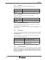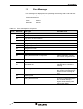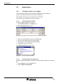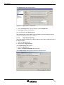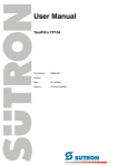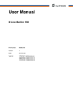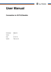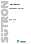
1
User Manual
Connection to 3S symbolic
Part Number:
80 860.632
Version:
2
Date:
25.11.2005
Valid for:
TSwin .net 4.0x
TSwin .net 4.1x
Version
1
2
Date
04.07.2005
25.11.2005
Modifications
First edition
Validation extended, chapter "Important Notes" added
This manual, including all illustrations contained herein, is copyright protected. Use of this manual by any third
party in departure from the copyright provision is forbidden. No part of this manual may be reproduced, translated or electronically or photographically archived or altered without the express written consent from Sütron
electronic GmbH. Violations shall be cause for damage liability.
Sütron electronic reserves the right to make any changes that contribute to technical improvement.
Overall Table of Contents
Overall Table of Contents
1
2
Important Notes ....................................................................................................... 1-1
1.1
Symbols .................................................................................................... 1-1
1.2
Safety Notes ............................................................................................. 1-1
1.3
Intended Use............................................................................................. 1-1
1.4
Target Group............................................................................................. 1-2
3S symbolic ............................................................................................................. 2-1
2.1
2.1.1
Single Variables ................................................................................... 2-1
2.1.2
String Variables ................................................................................... 2-1
2.2
A
Data Types................................................................................................ 2-1
Programming ............................................................................................ 2-1
2.2.1
Protocol Parameters ............................................................................ 2-1
2.2.1.1
Baud Rate...................................................................................................................2-1
2.2.1.2
Parity...........................................................................................................................2-2
2.2.1.3
Data Bits .....................................................................................................................2-2
2.2.1.4
Stop Bits .....................................................................................................................2-2
2.2.1.5
Waiting Time for Response ........................................................................................2-2
2.2.1.6
Delay until Connection Set-Up....................................................................................2-2
2.2.1.7
Byte Order ..................................................................................................................2-3
2.2.1.8
Controllers ..................................................................................................................2-3
2.2.1.9
Path for Variable List *.sym ........................................................................................2-3
2.2.2
Polling Area ......................................................................................... 2-3
2.2.3
Status Messages ................................................................................. 2-3
2.2.4
Date and Time ..................................................................................... 2-4
2.2.5
Variant Buffer ....................................................................................... 2-4
2.2.6
Tables .................................................................................................. 2-4
2.2.7
Physical Connection ............................................................................ 2-5
2.2.7.1
Pin Assignment for Operating Devices with an Universal Interface............................2-5
2.2.7.2
Cable SER1 RS232 - Schraml PLC FWM105 ............................................................2-6
2.2.7.3
Cable SER1 RS232 - Schraml SPS FWM160............................................................2-6
2.3
Error Messages......................................................................................... 2-7
2.4
Applications............................................................................................... 2-8
2.4.1
CoDeSys Version 2.2 or Higher........................................................... 2-8
2.4.1.1
Declaring Global Variables .........................................................................................2-8
2.4.1.2
Activate Output into Symbol File.................................................................................2-8
2.4.1.3
Target System Settings ............................................................................................2-10
2.4.1.4
Variable List ..............................................................................................................2-11
Index ........................................................................................................................A-1
i
Overall Table of Contents
ii
Important Notes
1
Important Notes
1.1
Symbols
The symbols in this manual are used to draw your attention on notes and dangers.
Danger
This symbol is used to refer to instructions wich, if ignored or not carfully followed
could result in personal injury.
Note
This symbol indicates application tips or supplementary notes.
Reference to source of information
This symbol refers to detailed sources of information on the current topic.
1.2
Safety Notes
–
Read this manual carefully before using the operating device. Keep this manual
in a place where it is always accessible to all users.
–
Proper transportation, handling and storage, placement and installation of this
product are prerequisites for its subsequent flawless and safe operation.
–
This user manual contains the most important information for the safe operation
of the device.
–
The user manual, in particular the safety notes, must be observed by all personnel working with the device.
–
Observe the accident prevention rules and regulations that apply to the operating
site.
–
Installation and operation must only be carried out by qualified and trained personnel.
1.3
Intended Use
–
The device is designed for use in the industry.
–
The device is state-of-the art and has been built to the latest standard safety requirements. However, dangerous situations or damage to the machine itself or
other property can arise from the use of this device.
–
The device fulfills the requirements of the EMC directives and harmonized European standards. Any modifications to the system can influence the EMC behavior.
1-1
Important Notes
1.4
Target Group
All configuration and programming work in connection with the automation system
must be performed by trained personnel only (e.g. qualified electricians, electrical engineers).
The configuration and programming personnel must be familiar with the safety concepts of automation technology.
1-2
3S symbolic
2
3S symbolic
The protocol provides random read and write access to all global data objects of the
controller.
The programming software adopts the data objects of the project_name.SYM file
which are created when the CoDeSys project is compiled.
The connected operating device uses the symbolic name to access a data object.
2.1
Data Types
The length of a variable is determined by the length defined in the programming software CoDeSys.
2.1.1
Single Variables
You can access variables of the following type: BOOL, BYTE, WORD, DWORD,
SINT, INT, DINT, USINT, UINT, UDINT, REAL, and STRING. Floating point numbers
are interpreted in IEEE format. The variable type REAL is required for this purpose.
2.1.2
String Variables
For string variables, the variable type STRING(N) is used, where N is the length of
the string.
2.2
Programming
2.2.1
Protocol Parameters
With the protocol parameters, you can adapt the communication of the controller
used.
2.2.1.1
Baud Rate
This parameter specifies the communication rate.
Table 2-1
Baud rate
Configurable Values
(Baud)
Default Value
4800
9600
19200
38400
X
2-1
3S symbolic
2.2.1.2
Parity
This parameter specifies the parity used to control the communication.
Table 2-2
Parity
Configurable Values
Default Value
None
X
Even
Odd
2.2.1.3
Data Bits
This parameter specifies the number of data bits.
Table 2-3
Data bits
Configurable Values
Default Value
5
6
7
8
2.2.1.4
X
Stop Bits
This parameter specifies the number of stop bits.
Table 2-4
Stop bits
Configurable Values
Default Value
1
X
1.5
2
2.2.1.5
Waiting Time for Response
This parameter specifies how long the operating device waits for a response from the
PLC.
Table 2-5
Waiting time for response
Configurable Values
Default Value
100 ms to 25500 ms
1000 ms
2.2.1.6
Delay until Connection Set-Up
This parameter specifies the waiting time after which the operating device starts the
communication.
Table 2-6
2-2
Delay until connection set-up
Configurable Values
Default Value
5 s to 255 s
5s
3S symbolic
2.2.1.7
Byte Order
This parameter specifies the destination hardware's CPU type.
Table 2-7
Byte order
Configurable Values
Default Value
Intel
Motorola
X
2.2.1.8
Controllers
This parameter specifies the runtime system of the controller.
Table 2-8
Controllers
Configurable Values
Default Value
Standard
X
PLCWinNT
2.2.1.9
Path for Variable List *.sym
This parameter specifies the directory in which the variable list *.sym is stored.
To select a directory, click the Browse button.
The variable list *.sym is created by the programming software CoDeSys when compilation takes place.
2.2.2
Polling Area
The poll area is used to manage the write coordination byte (WCB), the serial message channel and the LEDs in the function keys. This area is continuously polled by
the operating device.
This protocol requires you to set up the poll area with three single variables.
Table 2-9
Data types for the poll area
Area
Valid Data Types
KBS (write coordination byte)
BYTE, USINT, WORD, UINT
Message Channel
WORD, UINT
Function Key LEDs
BYTE, USINT, WORD, UINT, DWORD,
UDINT, ARRAY[1..N]
2.2.3
Status Messages
Status messages are the static assignment of flags (bits) in the controller to plain text
messages in the operating device. For status message addressing, use the data
types BYTE, USINT, WORD, UINT, DWORD, UDINT, or ARRAY[1..N]. The following
applies when using ARRAY: The type size multiplied by N provides the size of the
message system in bytes.
2-3
3S symbolic
2.2.4
Date and Time
The variables for synchronizing the time and date must use the data types USINT or
ARRAY [1..N] OF BYTE.
Table 2-10
Byte lengths for the date and time
Variable
Length
Date with a 2-digit year
3 Bytes
Date with a 4-digit year
4 Bytes
Time
3 Bytes
Weekday
1 Byte
2.2.5
Variant Buffer
The variable for the variant buffer must use the data type BYTE or USINT.
2.2.6
Tables
The variable for representation of tables must use the data type ARRAY [1..N]. The
ARRAY [1..N] has to be of one of the following base data types:
2-4
–
BOOL,
–
BYTE,
–
WORD,
–
DWORD,
–
SINT,
–
INT,
–
DINT,
–
USINT,
–
UINT,
–
UDINT,
–
REAL or
–
STRING.
3S symbolic
2.2.7
Physical Connection
Plug-in connectors on the operating device for connection to the controller.
2.2.7.1
Pin Assignment for Operating Devices with an Universal Interface
Table 2-11
Pin assignment RS232
Pin
Designation
Function
6
TD
Transmitted Data
15
CTS
Clear to send
17
RTS
Request to send
18
RD
Received data
25
SGND
Signal Ground
2-5
3S symbolic
2.2.7.2
Cable SER1 RS232 - Schraml PLC FWM105
The following cabling diagram applies to operating devices with an universal interface only.
Operating Device
RTS
CTS
TD
RD
SGND
Schraml
FWM105
17
4
15
6
6
WH
WH
3
18
BN
BN
2
25
GY
GY
5
RxD
TxD
GND
D-SUB
Male Connector
9 Pin
D-SUB
Male Connector
25 Pin
Both ends of the shield are connected to the metallic housing.
2.2.7.3
Cable SER1 RS232 - Schraml SPS FWM160
The following cabling diagram applies to operating devices with an universal interface only.
Operating Device
RTS
CTS
TD
RD
SGND
Schraml
FWM160
17
15
6
5
18
4
25
3
D-SUB
Male Connector
25 Pin
TxD
GND
RJ45
Connector
5 Pin
Both ends of the shield are connected to the metallic housing.
2-6
RxD
3S symbolic
2.3
Error Messages
Error messages are displayed on the operating device along with a code and subcode. Error messages are composed as follows:
Communication Error
Table 2-12
Code
XXXXX
Subcode
XXXXX
Retries
XXXXX
Error messages for 3S symbolic
Code
Subcode
Error Type
50
03
Framing error on serial interface
05
CRC error on serial interface
06
Parity error on serial interface
10
Poll area error
10
Wrong telegram length
20
Wrong telegram ident number
30
Wrong block number
40
Wrong checksum
50
Negative acknowledgement
60
Waiting time exceeded: no response
60
70
80
Possible Cause
No poll area defined
Cable interruption, connection cut-off, wrong baud rate
Error from controller
50
No service
Wrong service code
51
No variable list
Variable list in controller is
missing
20
Variable types not the same
Recompile the project using
the current symbol file and reload it into the operating device.
30
Invalid symbol
40
Waiting time exceeded
There is no valid symbol list in
the controller.Specify a
higher value for Delay until
Connection Set-Up
2-7
3S symbolic
2.4
Applications
2.4.1
CoDeSys Version 2.2 or Higher
The programming software takes the global variables from the symbol file
project_name.SYM and inserts them into the variable list.
The symbolic names cannot be longer than 80 characters.
The entries in the variable list cannot be modified.
2.4.1.1
Declaring Global Variables
To declare global variables in CoDeSys:
1. Select Auto Declare from the Edit menu.
The Declare Variable dialog opens.
Figure 2-1
Example of a variable declaration for global variables
2. Select the VAR_GOBAL class from the Class field.
3. Enter a name (Message) and a type (WORD).
4. Repeat step 3 for all additional global variables.
5. Click OK to confirm your input.
The Global_Variables window opens.
Figure 2-2
Window Global variables
2.4.1.2
Activate Output into Symbol File
Specify the following settings in CoDeSys to write the global variables into a symbolic
file.
1. Select Options from the Project menu.
2. Select Symbol configuration.
2-8
3S symbolic
The Options dialog will look as follows:
Figure 2-3
Dialog Options - symbol configuration
3. Select the Dump symbol entries check box.
4. Click the Configure symbol file button.
The Set object attributes window opens.
Figure 2-4
Dialog Set object attributes
5. Select the Global variables entry.
6. Click OK to confirm your selection.
You are returned to the Options dialog.
Now you need to specify the position where the symbol file is to be stored.
1. Select Directories from the Options dialog.
2-9
3S symbolic
The Options dialog will look as follows:
Figure 2-5
Dialog Options - directories
2. From the Project area, select a directory for the compile files.
3. Click OK to confirm your selection.
You are returned to the Options dialog.
The symbol file will not be created until a compilation process takes place and is
stored in the same directory as the project!
2.4.1.3
Target System Settings
Select the following settings for the target system to ensure the symbol file is sent to
the target system:
1. Open the Resources tab.
2. Double-click Target settings.
The Target settings dialog opens.
3. Open the General tab.
4. Select the Download Symbol File check box.
The Target settings dialog might look like the example below:
Figure 2-6
2-10
Dialog Target settings
3S symbolic
2.4.1.4
Variable List
The programming software automatically places the symbolic variable entries created in the example into the variable list if you specified the correct directory and
name in the communications parameters.
Figure 2-7
Variable list
This makes the variables globally available in the programming software.
2-11
3S symbolic
2-12
Index
A Index
Numerics
3S symbolic....................................................... 2-1
C
Cable SER1 RS232
Schraml PLC FWM105 ............................. 2-6
Schraml SPS FWM160 ............................. 2-6
I
Important notes ................................................. 1-1
Intended use ..................................................... 1-1
P
Protocol parameters
3S symbolic .............................................. 2-1
S
Safety notes ...................................................... 1-1
Symbols ............................................................ 1-1
T
Target group ..................................................... 1-2
A-1
Index
A-2
Sütron electronic GmbH
Kurze Straße 29
D-70794 Filderstadt
Phone: 0049 711 / 77098-0
Fax:
0049 711 / 77098-60
E-mail: [email protected]
Internet: www.suetron.com