1
Kramer Electronics, Ltd.
USER MANUAL
Models:
PIP-400, Picture in Picture Inserter / Quad Split
PIP-500, Picture in Picture Inserter / Quad Split
Contents
Contents
1
2
2.1
3
4
5
6
6.1
7
7.1
Introduction
Getting Started
Quick Start
Overview
Your Picture in Picture Inserter / Quad Split Machines
Installing on a Rack
Connecting the PIP-500 Picture in Picture Inserter / Quad Split
Connecting a PC
Configuring and Operating Your PIP-500
Using the Menu
1
1
1
3
4
9
10
12
13
13
7.1.1
7.1.2
7.1.3
7.1.4
The Mode Submenu
The Video Settings Submenu
The Presets Submenu
The Labeling Submenu
15
16
17
17
7.2
Displaying the Layers in the PIP Mode
18
7.2.1
Selecting a Different Channel as the Background
19
8
8.1
8.2
8.3
9
10
Firmware Upgrade
Downloading from the Internet
Connecting the PC to the RS-232 Port
Upgrading Firmware
Technical Specifications
Communication Protocol
20
20
20
20
22
23
Figures
Figure 1: PIP-400 Picture in Picture Inserter / Quad Split
Figure 2: PIP-500 Picture in Picture Inserter / Quad Split
Figure 3: Connecting the PIP-500 Picture in Picture Inserter / Quad Split
Figure 4: Connecting a PC without using a Null-modem Adapter
Figure 5: The PIP-500 Menu Guide
Figure 6: The PIP Mode
Figure 7: The QUAD Mode
Figure 8: Goal Screen
Figure 9: System Status Screen
5
6
11
12
14
15
15
21
21
i
Contents
Tables
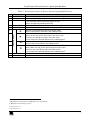
Table 1: Front Panel Picture in Picture Inserter / Quad Split Features
Table 2: Rear Panel Picture in Picture Inserter / Quad Split Features
Table 3: The PIP-500 Main Menu Items
Table 4: The MODE Submenu Features
Table 5: PIP Sizing and Positioning Features
Table 6: Recommended PIP sizes
Table 7: Video Settings Submenu Features
Table 8: Presets Submenu Features
Table 9: Technical Specifications of the Picture in Picture Inserter / Quad Split Machines
Table 10: Protocol Definitions
Table 11: Instruction Codes for the Communication Protocol
ii
7
8
13
15
16
16
16
17
22
23
24
KRAMER: SIMPLE CREATIVE TECHNOLOGY
Introduction
1
Introduction
Welcome to Kramer Electronics (since 1981): a world of unique, creative and
affordable solutions to the infinite range of problems that confront the video,
audio and presentation professional on a daily basis. In recent years, we have
redesigned and upgraded most of our line, making the best even better! Our
500-plus different models now appear in 8 Groups1, which are clearly defined
by function.
Congratulations on purchasing your Kramer PIP-400 Picture in Picture
Inserter / Quad Split and/or PIP-500 Picture in Picture Inserter / Quad Split,
which are ideal for:
Video production studios for source monitoring
Teleconferencing using one screen
Satellite, TV, home theater multi-channel monitoring
Security applications
The package includes the following items:
PIP-400 or PIP-500
Power cord and Null-modem adapter (for control via RS-232)
This user manual2
2
Getting Started
We recommend that you:
Unpack the equipment carefully and save the original box and packaging
materials for possible future shipment
Review the contents of this user manual
Use Kramer high performance high resolution cables3
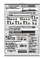
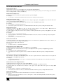
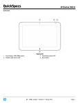
2.1 Quick Start
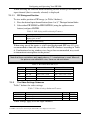
This PIP-500 quick start chart summarizes the basic setup and operation
steps4.
1 GROUP 1: Distribution Amplifiers; GROUP 2: Video and Audio Switchers, Matrix Switchers and Controllers; GROUP 3:
Video, Audio, VGA/XGA Processors; GROUP 4: Interfaces and Sync Processors; GROUP 5: Twisted Pair Interfaces;
GROUP 6: Accessories and Rack Adapters; GROUP 7: Scan Converters and Scalers; and GROUP 8: Cables and Connectors
2 Download up-to-date Kramer user manuals from our Web site at http://www.kramerelectronics.com
3 The complete list of Kramer cables is on our Web site at http://www.kramerelectronics.com
4 This quick start also applies to the PIP-400 which has four sets of inputs instead of five
1
Getting Started
INPU TS
1
2
3
4
5
LAYE R FR EEZE
ENTER
ES C
OUTPUT
CV
B-Y
Y/C
INPUT 4
CV
Y/C
INPUT 5
Y
B-Y
CV
R-Y
Y/C
Y
B-Y
R-Y
Y
INPUT 1
CV
INPUT 2
B-Y
CV
INPUT 3
B-Y
CV
Y/C
Y
R-Y
B-Y
Y/C
Y
Y/C
R-Y
Y
2
3
QUAD OUT
CV
Y/C
R-Y
MENU Items:
INPUTS
1
R-Y
4
5
LAYER FREEZE
MODE:
OSD:
BORDER:
VIDEO SETTINGS:
ENTER
ESC
INPUT SELECT:
OUTPUT STANDARD:
PRESETS:
2
KRAMER: SIMPLE CREATIVE TECHNOLOGY
Overview
3
Overview
The high performance PIP-400/PIP-500 is a picture-in-picture inserter for
composite video, s-Video (YC) and component video (YUV1).
The PIP-400/PIP-500 features:
A multi standard picture-in-picture video inserter designed to accept up to
five2 video sources and display them all on the same screen simultaneously3
Five2 sets of composite video, s-Video and component video inputs, and a
composite video, s-Video and component video output
A dedicated composite video and s-Video QUAD output to display four
quarter-sized pictures4 on one screen (each in its own quad)
Three operation modes: Single, PIP and QUAD
Non-volatile memory that retains the last setting, after switching the
power off and then on again5
Using the PIP-400/PIP-500 you can do the following:
Position sources on the screen as desired and select their size from a list
Put a text label in each inserted picture
Put a border around each inserted picture
Use sources of different formats and standards6
In addition, the PIP-400/PIP-500:
Includes 10-bit video A/D and D/A converters throughout the unit, to
ensure the highest quality video
Is controllable via the front panel buttons and a user-friendly OSD and
LCD, as well as via RS-232
Is dependable, rugged, and fits in two vertical spaces of a standard 19” rack
1 Y, B-Y, R-Y (sometimes called Y, Pb/Cb, Pr/Cr)
2 Four for the PIP-400
3 In two layers
4 Channels 1 to 4
5 Provided that the last setting was valid for at least 30 seconds before switching the machine OFF
6 For example, a PAL s-Video input could be inserted into a composite video NTSC source, and outputted to composite
video, s-Video and component video formats
3
Your Picture in Picture Inserter / Quad Split Machines
To achieve the best performance:
Connect only good quality connection cables, thus avoiding interference,
deterioration in signal quality due to poor matching, and elevated noiselevels (often associated with low quality cables)
Avoid interference from neighboring electrical appliances and position your
Kramer PIP-400/PIP-500 away from moisture, excessive sunlight and dust
4
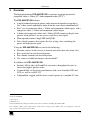
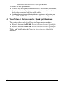
Your Picture in Picture Inserter / Quad Split Machines
This section defines each of the Picture-in-Picture Inserter machines:
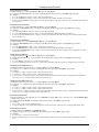
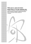
Figure 1 illustrates the PIP-400 Picture in Picture Inserter / Quad Split
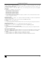
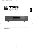
Figure 2 illustrates the PIP-500 Picture in Picture Inserter / Quad Split
Table 1 and Table 2 define the Picture in Picture Inserter / Quad Split
machines.
4
KRAMER: SIMPLE CREATIVE TECHNOLOGY
Your Picture in Picture Inserter / Quad Split Machines
INPUTS
1
2
3
4
LAYER FREEZE
INPUT 4
CV
Y/C
B-Y
R-Y
CV
INPUT 2
B-Y
CV
INPUT 3
R-Y
CV
B-Y
Y/C
Y
ESC
QUAD OUT
Y
INPUT 1
CV
ENTER
R-Y
Y/C
RS-232
B-Y
Y/C
Y
RELAY
OUTPUT
CV
B-Y
Y/C
Y
Y/C
R-Y
Y
R-Y
FUSE
Figure 1: PIP-400 Picture in Picture Inserter / Quad Split
5
Your Picture in Picture Inserter / Quad Split Machines
INPUTS
1
INPUT 4
CV
Y/C
B-Y
R-Y
CV
Y/C
R-Y
4
5
LAYER FREEZE
CV
B-Y
R-Y
CV
R-Y
ESC
CV
RELAY
Y/C
RS-232
B-Y
Y/C
Y
Y/C
OUTPUT
B-Y
Y/C
Y
CV
INPUT 3
B-Y
ENTER
QUAD OUT
Y
INPUT 2
B-Y
Y/C
Y
3
INPUT 5
Y
INPUT 1
CV
2
R-Y
Y
R-Y
FUSE
Figure 2: PIP-500 Picture in Picture Inserter / Quad Split
6
KRAMER: SIMPLE CREATIVE TECHNOLOGY
Your Picture in Picture Inserter / Quad Split Machines
Table 1: Front Panel Picture in Picture Inserter / Quad Split Features
Feature
POWER Switch
LCD Display
2
INPUT Buttons
4
5
6
LAYER Button
3
FREEZE Button
7
8
9
Navigation Buttons
#
1
2
3
10 ENTER Button
11 ESC Button
Function
Illuminated switch for turning the unit ON or OFF
1
Displays data including the operation mode and the menu (2 lines at a time)
In the SINGLE mode: selects the input to switch to the output
In the PIP mode: selects the input to appear in front
Selects an input for positioning and sizing
When in the PIP mode, press to access the PIP Sizing and Position menu directly
Press to freeze/unfreeze the output video image
4
Moves the selected image to the left in the PIP mode
5
Moves to the previous character in the Labeling menu
Moves the selected image upwards in the PIP mode4
Moves up one step (in the same level) in the OSD screen
Increases the range by one step in the OSD screen
5
Use to change the selected character in the Labeling menu
4
Moves the selected image to the right in the PIP mode
5
Moves to the next character in the Labeling menu
4
Moves the selected image downwards in the PIP mode
Moves down one step (in the same level) in the OSD screen
Decreases the range by one step in the OSD screen
5
Use to change the selected character in the Labeling menu
Displays the main menu; moves to the next level; confirms a command
Exits the OSD Menu; moves back to the previous level; stops the execution of a command
1 See Figure 5
2 PIP-400 has four input buttons and PIP-500 has five input buttons
3 Illuminates when the image is frozen
4 See section 7.1.1.1
5 See section 7.1.4
7
Your Picture in Picture Inserter / Quad Split Machines
Table 2: Rear Panel Picture in Picture Inserter / Quad Split Features
Feature
CV BNC Connector
13
Y BNC Connector
16
17
18
19
20
21
22
23
24
25
26
27
B-Y BNC Connector
Function
Connects to the composite video source
Connects to the component2 video source
R-Y BNC Connector
Y/C 4p Connector
CV BNC Connector
Y BNC Connector
B-Y BNC Connector
R-Y BNC Connector
Y/C 4p Connector
PROG. (IN)
RS-232 Port
Power Connector with FUSE
RELAY Terminal Block
Y/C 4p Connector
OUTPUT
15
QUAD
OUT
14
INPUT 11
#
12
CV BNC Connector
Connects to the s-Video source
Connects to the composite video acceptor
2
Connects to the component video acceptor
Connects to the s-Video acceptor
Push in to upgrade to the latest Kramer Firmware (see section 8)
Connects to the PC or other serial controller
AC connector enabling power supply to the unit
For future use
Connects to the s-Video quad acceptor
Connects to the composite video quad acceptor
1 The PIP-400 has 4 sets of inputs; the PIP-500 has 5 sets. Each set includes CV; Y, B-Y, R-Y; and Y/C
2 For component video, connect all 3 connectors: Y, B-Y, R-Y (also known as Y, Pb/Cb, Pr/Cr; or YUV)
8
KRAMER: SIMPLE CREATIVE TECHNOLOGY
Installing on a Rack
5
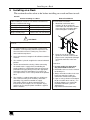
Installing on a Rack
This section describes what to do before installing on a rack and how to rack
mount.
Before Installing on a Rack
Before installing on a rack, be sure that the environment is
within the recommended range:
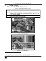
How to Rack Mount
To rack-mount a machine:
1
Attach both ear brackets to the
machine. To do so, remove the
screws from each side of the machine
(5 on each side), and replace those
screws through the ear brackets.
2
Place the ears of the machine
against the rack rails, and insert the
proper screws (not provided) through
each of the four holes in the rack
ears.
Operating temperature range +5 to +45 Deg. Centigrade
Operating humidity range
5 to 65% RHL, non-condensing
Storage temperature range
-20 to +70 Deg. Centigrade
Storage humidity range
5 to 95% RHL, non-condensing
CAUTION!!
When installing on a 19" rack, avoid hazards by taking
care that:
1 It is located within the recommended environmental
conditions, as the operating ambient temperature of a
closed or multi unit rack assembly may exceed the
room ambient temperature.
2 Once rack mounted, enough air will still flow around the
machine.
3 The machine is placed straight in the correct horizontal
position.
4 You do not overload the circuit(s). When connecting
the machine to the supply circuit, overloading the
circuits might have a detrimental effect on overcurrent
protection and supply wiring. Refer to the appropriate
nameplate ratings for information. For example, for
fuse replacement, see the value printed on the product
label.
5 The machine is earthed (grounded) in a reliable way
and is connected only to an electricity socket with
grounding. Pay particular attention to supply
connections other than direct connections to the
branch circuit (for example, the use of power strips),
and that you use only the power cord that is supplied
with the machine.
Note that:
In some models, the front panel
may feature built-in rack ears
Detachable rack ears can be removed
for desktop use
Always mount the machine in the rack
before you attach any cables or
connect the machine to the power
If you are using a Kramer rack adapter
kit (for a machine that is not 19"), see
the Rack Adapters user manual for
installation instructions (you can
download it at:
http://www.kramerelectronics.com)
9
Connecting the PIP-500 Picture in Picture Inserter / Quad Split
6
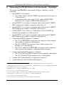
Connecting the PIP-500 Picture in Picture Inserter / Quad Split
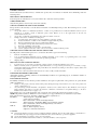
To connect your PIP-5001 as the example in Figure 3 illustrates, do the
following2:
1.
On the INPUT 1 set3 connect4:
An s-Video source to the Y/C INPUT 4p connector (for example, an
s-Video player 1)
A component video source to the Y, B-Y, and R-Y INPUT BNC
connectors (for example, a BETACAM video player 1)
2.
On the INPUT 2 set4 connect a composite video source to the CV INPUT
BNC connector (for example, a composite video player 2)
3.
On the INPUT 3 set4 connect a composite video source to the CV INPUT
BNC connector (for example, a composite video player 3)
4.
On the INPUT 4 set4 connect an s-Video source to the Y/C INPUT 4p
connector (for example, an s-Video player 4)
5.
On the INPUT 5 set4 connect a composite video source to the CV INPUT
BNC connector (for example, a composite video player 5)
6.
Connect the OUTPUT connectors5, as follows:
The CV OUTPUT BNC connector to the composite video acceptor
(for example, a composite video display)
The Y/C OUTPUT 4p connector to the s-Video acceptor (for
example, an s-Video display)
The Y, B-Y, and R-Y OUTPUT BNC connectors to the component
video acceptor (for example, a component video projector)
7.
Connect the QUAD OUT6 connectors, as follows7:
The CV QUAD OUT BNC connector to the composite video display
The Y/C QUAD OUT 4p connector to the s-Video display
8.
Connect a PC or other controller, if required (see section 6.1).
9.
Connect the power cord8 (not illustrated in Figure 3).
1 From this section on, all the information is relevant to the PIP-400 and PIP-500 machines, unless noted otherwise
2 Switch OFF the power on each device before connecting it to your PIP-500. After connecting your PIP-500, switch ON its
power and then switch on the power on each device
3 PIP-200xl has two sets of inputs, the PIP-300 has three sets of inputs
4 You do not have to connect all the inputs in each set
5 If only one output is required, connect that output to the PIP-500, and leave the other outputs unconnected
6 All four inputs (1 to 4) must be connected to achieve a good quality quad split output
7 You do not have to connect both QUAD outputs
8 We recommend that you use only the power cord that is supplied with this machine
10
KRAMER: SIMPLE CREATIVE TECHNOLOGY
Connecting the PIP-500 Picture in Picture Inserter / Quad Split
s-Video
Player 4
Betacam
Video Player 1
s-Video
Player 1
Composite
Video Player 2
Component
Video
Projector
Composite
Video Player 5
Composite
Video Player 3
Composite
Video Display
Composite
Video Quad
Display
s-Video
Quad
Display
s-Video
Display
Figure 3: Connecting the PIP-500 Picture in Picture Inserter / Quad Split
11
Connecting the PIP-500 Picture in Picture Inserter / Quad Split
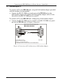
6.1 Connecting a PC
To connect a PC to the PIP-500 unit, using the Null-modem adapter provided
with the machine (recommended):
Connect the RS-232 DB9 rear panel port on the PIP-500 unit to the
Null-modem adapter and connect the Null-modem adapter with a 9-wire
flat cable to the RS-232 DB9 port on your PC
To connect a PC to the PIP-500 unit, without using a Null-modem adapter:
Connect the RS-232 DB9 port on your PC to the RS-232 DB9 rear panel
port on the PIP-500 unit, as Figure 4 illustrates
PIN 5 Connected to PIN 5 (Ground)
PIN 3 Connected to PIN 2
PIN 2 Connected to PIN 3
Female DB9 (From PC)
Male DB9
PIN 4 Connected to PIN 6
PINS 8, 7, 1 Connected together
If a Shielded cable is used, connect the shield to PIN 5
Figure 4: Connecting a PC without using a Null-modem Adapter
12
KRAMER: SIMPLE CREATIVE TECHNOLOGY
Configuring and Operating Your PIP-500
7
Configuring and Operating Your PIP-500
You can configure and operate your PIP-500 via:
The front panel buttons, and/or
RS-232 serial commands transmitted by a touch screen system, PC, or
other serial controller
7.1 Using the Menu
Use the front panel buttons to activate the menu. The menu is displayed1 on
the LCD display2 and is also superimposed on the screen2, 3.
To use the PIP-500 menu, press the:
ENTER button to display the menu and accept changes
ESC button to move to the previous menu level
,
arrow buttons to select the menu items, size and position the input
display, adjust the numerical rates, and edit the text labeling
, arrow buttons to position the input display and to edit the text
labeling
An asterisk in parentheses indicates the current status on the screen. For
example, if the current OUTPUT SETTING is PAL, the OSD will show the
asterisk in brackets alongside PAL: “PAL (*)”.
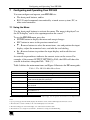
Table 3 defines the main menu items and Figure 5 illustrates the PIP menu guide:
Table 3: The PIP-500 Main Menu Items
Menu Item
MODE
OSD
BORDER
Function
Select between the SINGLE, PIP and QUAD modes, see section 7.1.1
Activates/deactivates the OSD menu4
Select a border around the image (applies to all channels) and select the
border COLOUR (WHITE or BLACK)
VIDEO SETTINGS
Adjust the CONTRAST, SATURATION and BRIGHTNESS (see section 7.1.2)
INPUT SELECT
Select between: COMPOSITE video, S-VIDEO or COMPONENT video, per
input channel
OUTPUT STANDARD Select between NTSC and PAL
PRESETS
Store and recall PRESETS (1 and 2), or use FACTORY DEFAULT5 settings,
see section 7.1.3
LABELING
Display, remove and edit the text label for the input channel, see section 7.1.4
1 The menu always displays only 2 lines at a time on the LCD display. Use the up/down arrow buttons to scroll up/down the
menu
2 Upon powering up, the LCD briefly displays the machine’s name, and the OSD displays the firmware version
3 The menu times out after a minute, both on the LCD display and on the OSD
4 The menu still appears on the LCD display even when deactivated in the OSD
5 The machine is set to Single mode, Channel 1, default video settings and default labeling
13
Configuring and Operating Your PIP-500
1/1
1/4
SINGLE
PIP SIZING
PIP
MODE
1/16
OFF
QUAD
ON
OSD
1/9
PIP POSITION
OFF
USE
ARROWS
TO MOVE
ON
BORDER
START
VIDEO
SETTINGS
OFF
WHITE
COLOUR
BLACK
CONTRAST
USE UP/DOWN
KEYS
SATURATION
USE UP/DOWN
KEYS
BRIGHTNESS
USE UP/DOWN
KEYS
COMPOSITE
INPUT
SELECT
S-VIDEO
COMPONENT
NTSC
OUTPUT
STANDARD
PAL
STORE
PRESETS
RECALL
EDIT LABEL
LABELING
LABEL ON
STORE PRESET 1
STORE PRESET 2
RECALL PRESET 1
RECALL PRESET 2
FACTORY DEFAULT
LABEL OFF
Figure 5: The PIP-500 Menu Guide
14
KRAMER: SIMPLE CREATIVE TECHNOLOGY
Configuring and Operating Your PIP-500
7.1.1
The Mode Submenu
Table 4 defines the MODE submenu features:
Table 4: The MODE Submenu Features
Mode
SINGLE
PIP
QUAD
2
Function
Displays one input channel at a time on the screen (full screen display). The LCD display
shows the display mode and the selected channel, for example, “Single Mode – Channel 2”
1
Displays all 5 input channels on the screen. Once the PIP mode is selected, the PIP SIZING
and PIP POSITION commands appear, as illustrated in Figure 6 (see section 7.1.1.1). The
LCD display shows “PIP Mode”
3
Displays 4 quarter-sized input channels over the screen (channels 1 to 4), as illustrated in
Figure 7. The LCD display shows “QUAD Mode”
Figure 6: The PIP Mode
Figure 7: The QUAD Mode
1 PIP-400 has four input channels
2 When using the QUAD output, the input and output color formats (PAL or NTSC) must be identical
3 All four inputs (1 to 4) must be connected to achieve a good quality quad split output
15
Configuring and Operating Your PIP-500
When selecting the SINGLE mode following the PIP or the QUAD mode, the
input channel (that is currently selected) is displayed.
7.1.1.1
PIP Sizing and Position
To size and/or position a PIP image (as Table 5 defines):
1. Press the desired input channel button (from 1 to 5)1. The input button blinks.
2. Select either PIP SIZING or PIP POSITION (using the up/down arrow
buttons) and press ENTER.
Table 5: PIP Sizing and Positioning Features
Menu Item
PIP SIZING
PIP POSITION
Function
Use the , arrow buttons to select between 1/1, 1/4, 1/9 and 1/16
2
display sizes or OFF
Use the , , and arrow buttons to position the selected channel
vertically and horizontally
When using one of the inputs as a full-sized background (PIP size 1/1), it is
recommended to limit the sizes of the other PIP windows according to Table
6. Combinations having window sizes larger than recommended, may result
in intermittent interruptions in the picture.
Note that these restrictions only apply when a 1:1 sized picture is used. When all
the pictures are reduced in size, there are no restrictions
Table 6: Recommended PIP sizes
1 PIP
1/4
2 PIPs
1/4 + 1/9
3 PIPs
1/9 + 1/9 + 1/16
4 PIPs
1/9 + 1/9 + 1/16 + 1/16
1/9
1/4 + 1/16
1/9 + 1/16 + 1/16
1/9 + 1/16 + 1/16 + 1/16
1/16
1/9 + 1/9
1/16 + 1/16 + 1/16
1/16 + 1/16 + 1/16 + 1/16
1/9 + 1/16
1/4 + 1/16 + 1/16
1/16 + 1/16
7.1.2
The Video Settings Submenu
Table 7 defines the video settings:
Table 7: Video Settings Submenu Features
Menu Item
CONTRAST
SATURATION
BRIGHTNESS
Function
Use the up/down arrow buttons to set the contrast
Use the up/down arrow buttons to set the saturation
Use the up/down arrow buttons to set the brightness
Range
0 to 100
0 to 100
0 to 100
Default
55
51
33
Video settings apply to all the input channels.
1 PIP-400 has four input channels
2 If OFF is selected, the selected input channel will not be displayed on the screen
16
KRAMER: SIMPLE CREATIVE TECHNOLOGY
Configuring and Operating Your PIP-500
7.1.3
The Presets Submenu
Table 8 defines the Presets submenu:
Table 8: Presets Submenu Features
Menu Item
1
STORE
RECALL
7.1.4
Function
Select PRESET 1 and PRESET 2 to store the mode settings (channel number
when in the SINGLE mode, size and positioning in PIP mode, and setting to
QUAD), the video settings (contrast, saturation and brightness) and the labeling
2
Recall PRESET 1 and PRESET 2 settings, or set to FACTORY DEFAULT
The Labeling Submenu
The labeling submenu lets you display labels over the input pictures, remove
them from the display or edit them. To turn labels on or off select the LABEL
ON or LABEL OFF items in the LABELING menu respectively.
The input pictures are labeled3 Channel 1 to Channel 5 by default4. You can
edit the text labels for each channel by using the labeling submenu:
Press ENTER on the LABELING submenu and choose the EDIT LABEL
command. The selected channel name appears with its first letter blinking
Use the
and
buttons to select the first desired letter5
Use the button to continue to the next letter
Use the button to return to the previous letter
Use the ENTER button to accept changes
For example, to change the labeling from CHANNEL 2 to SAT 3, do the following:
1.
Press the INPUT 2 button, and then press the ENTER button.
2.
Select LABELING and then EDIT LABEL from the menu.
The CHANNEL 2 label appears, and the first character is blinking.
3.
Press the button 16 times to change the letter C to S, and then press the
button to continue to the second letter (H).
4.
Press the button 7 times to change the letter H to A, and then press the
button to continue to the third letter.
5.
Press the button 19 times to change the letter A to T, and then press the
button to continue to the next letter.
1 When storing a new setting, wait 10 seconds for the setup to be saved
2 The machine is set to Single mode, Channel 1, default video settings and default labeling
3 In some versions, the labeling does not appear on the 1:1 sized image (in the PIP mode) or when the PIPs overlap
4 For PIP-400, Channel 1 to Channel 4
5 Characters cycle between a and z and between 1 and 0 and space
17
Configuring and Operating Your PIP-500
6.
Press the
press the
button 14 times to change the letter N to a blank space, and then
button to continue to the next letter.
7.
Press the button 15 times to change the letter N to 3, and then press the
button to continue to the next letter.
8.
Press the
9.
Press ENTER to accept changes.
or
buttons to change the remaining characters to blank spaces.
7.2 Displaying the Layers in the PIP Mode
To display a picture-in-picture on the screen, do the following:
1.
Select an input.
2.
Select the PIP mode and then size and position each layer as desired1.
3.
Press an INPUT button to bring forward that input on the screen.
1 Only one channel can be sized to 1:1, the others should be smaller in size or OFF (see Table 6)
18
KRAMER: SIMPLE CREATIVE TECHNOLOGY
Configuring and Operating Your PIP-500
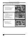
7.2.1
Selecting a Different Channel as the Background
In the following example, Channel 4 replaces channel 5 as the background.
A
The current screen shows:
Channel 5 in the background (PIP SIZING: 1:1)
Channel 1 in front (PIP SIZING: 1:4)
Channel 2 in front (PIP SIZING: 1:16)
Channel 3 in front (PIP sizing: 1:9)
Channel 4 in front (PIP sizing: 1:16)
B
Select Channel 4 and size it to 1:1 as follows:
A. Press INPUT 4
B. Press the LAYER button (or follow steps 1 to 3)
1. Press ENTER
2. Press ENTER again to select MODE
3. Scroll down to PIP and press ENTER
C. Press ENTER to select PIP SIZING
D. Press ENTER to size to 1:1
The current screen shows:
Channel 4 in front (PIP SIZING: 1:1)
Channels 1, 2, 3 and 5 are behind, unseen
C
Press INPUT button 1, 2, 3 or 5
The current screen shows:
Channel 4 in the background
Channels 1, 2, 3 and 4 are in front
19
Firmware Upgrade
8
Firmware Upgrade
The PIP-500 firmware is located in FLASH memory, which lets you upgrade
to the latest Kramer firmware version in minutes! The process involves:
Downloading from the Internet (see section 8.1)
Connecting the PC to the RS-232 port (see section 8.2)
Upgrading firmware (see section 8.3)
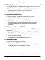
8.1 Downloading from the Internet
You can download the up-to-date file from the Internet. To do so:
1.
Go to our Web site at http://www.kramerelectronics.com and download the
relevant zip file from the Technical Support section.
2.
Extract this file to a folder (for example, C:\Program Files\KramerFlash).
3.
Create a shortcut on your desktop to the EXE file, and install the GOAL
TENDER programmer software, following the on-screen installation
instructions.
8.2 Connecting the PC to the RS-232 Port
Before installing the latest Kramer firmware version on a PIP-500 unit, do
the following:
1.
Connect the RS-232 DB9 rear panel port on the PIP-500 unit to the RS-232
DB9 COM port on your PC, via a straight pin-to-pin cable1 (no null-modem
is used in this case!).
2.
Push in the PROG. (IN) button.
3.
Connect the power to the PIP-500 unit and switch it ON.
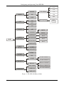
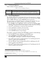
8.3 Upgrading Firmware
Follow these steps to upgrade the firmware:
1.
Double click the 1000-ISPV2 icon on the desktop.
The software immediately searches for communication between the PC and
the PIP-500, and the GOAL screen appears as follows:
1 For firmware upgrade via the RS-232 port, no Null-modem connection is required. The Null modem (supplied) is used for
control via RS-232, not for upgrading
20
KRAMER: SIMPLE CREATIVE TECHNOLOGY
Firmware Upgrade
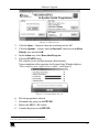
Figure 8: Goal Screen
2.
Click the Open… button to select the new firmware hex file1.
3.
Click the Options… button, select the Inverted2 check box in the Reset
Polarity area and click OK.
4.
In the Action area, select Erase then Program.
5.
Click the START button.
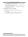
The software erases and then programs flash memory.
Upon completion of the operation, the System Status Window displays:
“Erase and program completed successfully” (see Figure 9).
Figure 9: System Status Screen
6.
Exit the programmer software.
7.
Disconnect the power on the PIP-500.
8.
Release the PROG. (IN) button.
9.
Connect the power on the PIP-500.
1 Located in the C:\Program Files\KramerFlash folder
2 In some models you need to select the Normal check box
21
Technical Specifications
9
Technical Specifications
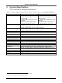
Table 9 includes the technical specifications1:
2
Table 9: Technical Specifications of the Picture in Picture Inserter / Quad Split Machines
INPUTS:
PIP-400
4 sets, each with:
1 composite video 1Vpp/75 on a
BNC connector
1 s-Video 1Vpp, 0.3Vpp/75 on a 4p
connector
1 component video 1Vpp, 0.7Vpp,
0.7Vpp/75 on BNC connectors
PIP-500
5 sets, each with:
1 composite video 1Vpp/75 on a
BNC connector
1 s-Video 1Vpp, 0.3Vpp/75 on a 4p
connector
1 component video 1Vpp, 0.7Vpp,
0.7Vpp/75 on BNC connectors
OUTPUTS:
1 component video 1Vpp, 0.7Vpp, 0.7Vpp / 75 on BNC connectors
1 s-Video 1Vpp, 0.3Vpp / 75 on a 4p connector
1 composite video 1Vpp / 75 on a BNC connector
QUAD OUTPUTS:
1 s-Video 1Vpp, 0.3Vpp / 75 on a 4p connector
1 composite video 1Vpp / 75 on a BNC connector
DIGITAL RESOLUTION:
10 bit
VIDEO BANDWIDTH:
5.4MHz
K-FACTOR:
0.9%
S/N RATIO:
64dB
DIFFERENTIAL PHASE:
0.8%
DIFFERENTIAL GAIN:
1.1%
LUMA NON-LINEARITY:
0.9%
CHROMA / LUMA DELAY:
<15ns
YC SEPARATION:
Adaptive 4-line digital comb filters
MEMORY:
Non-volatile memory for storage of 2 setups
CONTROL:
Front-panel and RS-232: PIP size, position and layer priority; motion
detection sensitivity (option); video ProcAmp functions; video zoom; freeze
POWER SOURCE:
Universal, 100-240VAC, 50/60Hz, 38VA
DIMENSIONS:
19” (W), 9.3” (D), 2U (H) rack mountable
WEIGHT:
4.1kg (9.1lbs) approx.
ACCESSORIES:
Power cord, null modem adapter
1 Measurements relate to composite video, unless otherwise stated
2 Specifications are subject to change without notice
22
KRAMER: SIMPLE CREATIVE TECHNOLOGY
Communication Protocol
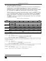
10 Communication Protocol1
This RS-232/RS-485 communication protocol uses four bytes of information as
defined below. A null-modem connection (pin 2 and pin 3 crossed; pins 5
connected together) is used to link the PIP unit to the controller unit (for example,
PC). The data rate is 9600 baud, with no parity, 8 data bits and 1 stop bit.
When switching (for example, instruction codes 1 and 2), the INPUT (7 bits)
is set as the input number, which is to be switched. Similarly, if switching is
done via the machine’s front-panel, then these bits are set with the INPUT
NUMBER, which was switched. For other operations, these bits are defined
according to the table.
Table 10: Protocol Definitions
7
MSB
0
6
5
DESTINATION
D
3rd byte
1
4th byte
2
INST3
RQ
BYTE25
BYTE24
BYTE23
BYTE36
BYTE35
BYTE34
BYTE33
BYTE37
0
0
REQUEST
LSB
1
0
INST1
INST0
BYTE22
BYTE21
BYTE20
BYTE32
BYTE31
BYTE30
0
0
0
INSTRUCTION
INST4
2nd byte
1
3
INST5
1st byte
1
4
BYTE3
LAST
1
INST2
INPUT
1st BYTE:
Bit 7 – Defined as 0
Bit 6 – “DESTINATION BIT”: 0 – information is sent from the PC to the PIP
1 – information is sent from the PIP to the PC
Bit 5 to Bit 0 (INST5…..INST0) – “INSTRUCTION” (6 bits)
The function that is to be performed is defined by the INSTRUCTION code (6 bits). Similarly, if a function is performed via
the machine’s keyboard, then the machine sends the appropriate INSTRUCTION code. The instruction codes are defined
according to the table below.
2nd BYTE:
Bit 7 – Defined as 1
Bit 6 – “REQUEST BIT”: 0 – normal operation
1 – requests the PIP to send current data to the PC
Bit 5 to Bit 0 (BYTE25…..BYTE20) – 2nd byte (6 bits)
If the request bit is set, then the PIP will reply by sending the data related to this instruction to the PC. If not set, then the PIP
performs the instruction and replies by returning the same 4 bytes (except for the DESTINATION BIT).
3rd BYTE:
Bit 7 – Defined as 1
Bit 6 to Bit 0 (BYTE36…..BYTE30) – 7 bits of BYTE3 (BYTE37 is in LAST byte)
4th BYTE:
Defined as 0x88 (ie. 88hex) for BYTE37 = 0; or 0xc8 for BYTE37 = 1
1 VER-0.1
23
Communication Protocol
Table 11: Instruction Codes for the Communication Protocol
INSTRUCTION
# (Hex)
Description
DEFINITION FOR SPECIFIC INSTRUCTION
BYTE2
BYTE3
0x00
0x01
0x02
Reset
0
Active input select 1 to 5 – select input number
Mode select
0
0x03
Store
0x04
0x09
Recall
0 to 0x02 – address to retrieve
Video input format 1 to 5 – input number
0x0A
Request video
input standard
1 to 5 – input number
0x0B
Video output
standard
0
0x10
0x11
0x12
0x13
0x1a
Error
Contrast
Saturation
Brightness
PIP size
0
0
0
0
1 to 5 – input number
0x1b
0x1c
0x1d
PIP position: X
PIP position: Y
Border
1 to 5 – input number
1 to 5 – input number
0
0x1e
Freeze
1 to 5 – input number
0x21
0x22
0x23
0x24
0x25
0x26
0x27
0x28
0x29
0x31
Label: character 1
Label: character 2
Label: character 3
Label: character 4
Label: character 5
Label: character 6
Label: character 7
Label: character 8
Label: character 9
OSD
1 to 5 – input number
1 to 5 – input number
1 to 5 – input number
1 to 5 – input number
1 to 5 – input number
1 to 5 – input number
1 to 5 – input number
1 to 5 – input number
1 to 5 – input number
0
0x39
Auto-save
0
0x3d
Identify machine
1
1 to 0x02 – address for storing
3
24
0
0
0 for single mode (non-PIP)
1 for PIP mode
2 for QUAD
0 to store
1 to erase
0
0 – CV
1 – Y/C
2 – YUV
1 – NTSC
2 – PAL (B,G, H, I)
3 – PAL-M
4 – PAL-N
5 – NTSC4.43
6 – SECAM
1 – NTSC
2 – PAL (B,G, H, I)
3 – PAL-M
4 – PAL-N
5 – NTSC4.43
0
0 to 100
0 to 100
0 to 100
1 – 1:1
2 – 1/4
3 – 1/9
4 – 1/16
0 to maximum to the right
0 to maximum to the bottom
0 – Off
1 – White border
2 – Black border
0 – Normal operation
1 – Frozen
Hex value of ASCII character
Hex value of ASCII character
Hex value of ASCII character
Hex value of ASCII character
Hex value of ASCII character
Hex value of ASCII character
Hex value of ASCII character
Hex value of ASCII character
Hex value of ASCII character
0 – OSD off
1 – OSD on
0 – Auto-save off
1 – Auto-save on
2 – for PIP-200 (reply)
3 – for PIP-300 (reply)
4 – for PIP-400 (reply)
5 – for PIP-500 (reply)
Software version (reply)
KRAMER: SIMPLE CREATIVE TECHNOLOGY
Communication Protocol
DETAILS OF INSTRUCTION SET
Instruction 0x00: Reset
When machine is turned on, it sends a Reset code to the PC (0x40 0x80 0x80 0x88).
If this code is sent to the switchers with Byte3 = 0, it will reset according to the present power-down settings. (See instruction
#4 for resetting the PIP to its factory default state).
Instruction 0x01: Input select
Sending this instruction will select the input number that is specified in Byte2.
For example:
To select input 2, send 0x01 0x82 0x80 0x88. The unit responds by sending 0x41 0x81 0x80 0x88
Instruction 0x02: Mode select
Sending this instruction with Byte3 = 0 will set the unit to output a single picture; setting Byte3 to any other value will set the
unit to work in Picture-In-Picture (PIP) mode.
To request the operation mode, set the RQ bit. The unit responds by setting Byte3 appropriately.
For example:
To set for PIP mode, send 0x02 0x80 0x81 0x88.
To find out the operation mode in this case, send 0x02 0xc0 0x80 0x88. The unit responds by sending 0x42 0x80 0x81 0x88.
Instruction 0x03: Store
Sending this instruction with Byte3 = 0 will store the unit'
s current settings in non-volatile memory. Byte2 selects the
memory address (1 or 2). If Byte3 = 1, then the memory'
s setting is cleared.
To inquire whether a setting is stored in a memory address, set the RQ bit. The unit responds by setting Byte3 as 0 if data is
saved, or 1 if not.
For example:
To save to memory 2, send 0x03 0x82 0x80 0x88.
To find out if data is stored in memory 2, send 0x03 0xc2 0x80 0x88. Since there is data stored, the unit responds by sending 0x43
0x80 0x80 0x88.
To erase memory 2, send 0x03 0x82 0x81 0x88.
Instruction 0x04: Recall
Sending this instruction with will recall the settings stored in non-volatile memory. Byte2 selects the memory address (1 or
2). To recall the factory reset settings, select byte2 = 0.
There is no inquire (RQ) for this instruction.
For example:
To recall from memory 1, send 0x04 0x81 0x80 0x88.
Instruction 0x09: Video Input Format
Sending this instruction selects the video format (Byte3) for an input (Byte2).
To inquire which video format is selected on an input, set the RQ bit. The unit responds by setting Byte3 appropriately.
For example:
To set input 4 for Y/C, send 0x09 0x84 0x81 0x88.
To find out the video format for input 4 in this case, send 0x09 0xc4 0x80 0x88. The unit responds by sending 0x49 0x84 0x81
0x88.
Instruction 0x0a: Request Video Input Standard
This "instruction" can only be used with the RQ bit set. It is used to inquire which video standard is detected on an input. The
unit responds by setting Byte3 appropriately.
For example:
To inquire which standard is detected on input 3, send 0x0a 0xc3 0x80 0x88. If a PAL-B input is present, then the unit responds by
sending 0x4a 0x83 0x81 0x88.
Instruction 0x0b: Video Output Standard
Sending this instruction selects the video output standard (Byte3).
NOTE: If the unit does not support the standard, then it will return an ERROR code (Instruction 0x10)
To request which video standard has been selected on the output, set the RQ bit. The unit responds by setting Byte3
appropriately.
For example:
To set the machine to output PAL, send 0x0b 0x80 0x81 0x88.
To find out the video format for in this case, send 0x0b 0xc0 0x80 0x88. The unit responds by sending 0x4b 0x80 0x81 0x88.
Instruction 0x10: Error
This is the code returned by the machine if invalid data is received (it is not really an instruction).
For example:
If the user sends 0x01 0x87 0x81 0x88 (ie. he tries to select input # 7 – which is an invalid input number), the unit will respond by
sending 0x50 0x80 0x80 0x88.
25
Communication Protocol
Instruction 0x11: Contrast
Send this instruction to set the CONTRAST (Byte3) of an input (Byte2).
To request the CONTRAST value of an input, set the RQ bit. The unit responds by setting Byte3 appropriately.
For example:
To set the CONTRAST of input 2 to 0x7b, send 0x11 0x82 0xfb 0x88.
To set the CONTRAST of input 2 to 0xac, send 0x11 0x82 0xac 0xc8 (MSB of BYTE3 is in LAST byte).
To find out the CONTRAST setting of input 2, send 0x11 0xc2 0x80 0x88. The unit would respond by sending 0x51 0xc2 0xac 0xc8
in the latter case.
Instruction 0x12: Saturation
Send this instruction to set the SATURATON (Byte3) of an input (Byte2).
To request the SATURATION value of an input, set the RQ bit. The unit responds by setting Byte3 appropriately.
For example:
To set the SATURATION of input 3 to 0x04, send 0x12 0x83 0x84 0x88.
To set the SATURATION of input 3 to 0xb6, send 0x12 0x83 0xb6 0xc8 (MSB of BYTE3 is in LAST byte).
To find out the SATURATION setting of input 3, send 0x12 0xc3 0x80 0x88. The unit would respond by sending 0x52 0xc3 0xb6
0xc8 in the latter case.
Instruction 0x13: Brightness
Send this instruction to set the BRIGHTNESS (Byte3) of an input (Byte2).
To request the BRIGHTNESS value of an input, set the RQ bit. The unit responds by setting Byte3 appropriately.
For example:
To set the BRIGHTNESS of input 1 to 0x73, send 0x13 0x81 0xf3 0x88.
To set the BRIGHTNESS of input 1 to 0xfe, send 0x13 0x81 0xfe 0xc8 (MSB of BYTE3 is in LAST byte).
To find out the BRIGHTNESS setting of input 1, send 0x13 0xc1 0x80 0x88. The unit would respond by sending 0x53 0xc1 0xf3
0x88 in the former case.
Instruction 0x1a: PIP size
Sending this instruction selects the PIP size (Byte3) of an input (Byte2)..
To inquire about the PIP size of one of the inputs, set the RQ bit. The unit responds by setting Byte3 appropriately.
For example:
To set the PIP size of input 2 to 1/9, send 0x1a 0x82 0x83 0x88.
To find out the PIP size of input 2 in this case, send 0x1a 0xc2 0x80 0x88. The unit responds by sending 0x5a 0xc2 0x83 0x88.
Instruction 0x1b: PIP position: X
Sending this instruction positions the x co-ordinate (Byte3) of an input (Byte2).
To request the x co-ordinate of an input, set the RQ bit. The unit responds by setting Byte3 appropriately.
For example:
To set the x co-ordinate of input 2 at 0x57, send 0x1b 0x82 0xd7 0x88.
To set the x co-ordinate of input 2 at 0x97, send 0x1b 0x82 0x87 0xc8.
To find out the x co-ordinate for input 2, send 0x1b 0xc2 0x80 0x88. The unit would respond by sending 0x5b 0xc2 0xd7 0x88 in
the former case, or by sending 0x5b 0xc2 0xd7 0xc8 in the latter case.
Instruction 0x1c: PIP position: Y
Sending this instruction positions the y co-ordinate (Byte3) of an input (Byte2).
To request the y co-ordinate of an input, set the RQ bit. The unit responds by setting Byte3 appropriately.
For example:
To set the y co-ordinate of input 2 at 0x14, send 0x1c 0x82 0x94 0x88.
To set the y co-ordinate of input 2 at 0x94, send 0x1c 0x82 0x94 0xc8.
To find out the y co-ordinate for input 2, send 0x1c 0xc2 0x80 0x88. The unit would respond by sending 0x5c 0xc2 0x94 0x88 in the
former case, or by sending 0x5c 0xc2 0x94 0xc8 in the latter case.
Instruction 0x1d: Border
Send this instruction to select whether there is a BORDER around the PIPs, and to select the color of the BORDER. Byte3
configures the selection.
To inquire about the BORDER, set the RQ bit. The unit responds by setting Byte3 appropriately.
For example:
To set a white border, send 0x1d 0x80 0x81 0x88.
To find out about the border, send 0x1d 0xc0 0x80 0x88. In this case the unit would respond by sending 0x5d 0xc0 0x81 0x88.
Instruction 0x1e: Freeze
Send this instruction to FREEZE or UNFREEZE an input.
To inquire if an input is frozen, set the RQ bit. The unit responds by setting Byte3 appropriately.
For example:
To freeze input 3, send 0x1e 0x83 0x81 0x88.
To find out whether input 3 is frozen, send 0x1e 0xc3 0x80 0x88. In this case the unit would respond by sending 0x5e 0xc3 0x81
0x88.
26
KRAMER: SIMPLE CREATIVE TECHNOLOGY
Communication Protocol
Instruction 0x21 to Instruction 0x29: Labeling
For these instructions, set Byte2 with the input number and set Byte3 is set with the hexadecimal value of the ASCII
character. The character number is defined from right to left (when read), with the right-hand most character = character 1. Up
to 9 characters are allowed in any label.
To request the character of a label, define Byte2 as above, and set the RQ bit. The unit responds by setting Byte3
appropriately.
For example:
To label input 3 as "KRAMER", send the following data:
0x26 0x83 0xcb 0x88 ("K" defined to character 6)
0x25 0x83 0xd2 0x88 ("R" defined to character 5)
0x24 0x83 0xc1 0x88 ("A" defined to character 4)
0x23 0x83 0xcd 0x88 ("M" defined to character 3)
0x22 0x83 0xc5 0x88 ("E" defined to character 2)
0x21 0x83 0xd2 0x88 ("R" defined to character 1)
To request character number 5 defined to input 3 in the example above (ASCII "R", ie. 0x52), send 0x25 0xc3 0x80 0x88. The unit
responds by sending 0x65 0xc3 0xd2 0x88.
Instruction 0x31: OSD
Send this instruction to select whether or not to display the OSD (On-Screen-Display). Note that the front-panel LCD is
independent of the OSD status.
To inquire if the OSD is on, set the RQ bit. The unit responds by setting Byte3 appropriately.
For example:
To turn on the OSD, send 0x31 0x80 0x81 0x88.
To inquire about the OSD setting, send 0x31 0xc0 0x80 0x88. In this case the unit would respond by sending 0x71 0xc0 0x81 0x88.
Instruction 0x39: Auto-save
Send this instruction to select whether or not to recall the unit'
s last settings when cycling power.
To inquire if the auto-save option is on, set the RQ bit. The unit responds by setting Byte3 appropriately.
For example:
To turn on the auto-save option, send 0x39 0x80 0x81 0x88.
To inquire about the auto-save setting, send 0x39 0xc0 0x80 0x88. In this case the unit would respond by sending 0x79 0xc0 0x81
0x88.
Instruction 0x3d: Identify machine
This instruction (inquiry) is used for machine identification. It can only be used with the RQ bit set. The user sends the
inquiry with the INSTRUCTION and Byte3 as defined above, and the unit answers with the appropriate value of Byte3.
For example:
If 0x3d 0xc1 0x80 0x88 is sent to a PIP-300, it would reply by sending 0x7d 0xc1 0x83 0x88
If 0x3d 0xc1 0x80 0x88 is sent to a PIP-400, it would reply by sending 0x7d 0xc1 0x84 0x88
If 0x3d 0xc3 0x80 0x88 is sent to a unit with version number 6.3, it would reply by sending 0x7d 0xc6 0x83 0x88
27
LIMITED WARRANTY
Kramer Electronics (hereafter Kramer) warrants this product free from defects in material and workmanship under the
following terms.
HOW LONG IS THE WARRANTY
Labor and parts are warranted for seven years from the date of the first customer purchase.
WHO IS PROTECTED?
Only the first purchase customer may enforce this warranty.
WHAT IS COVERED AND WHAT IS NOT COVERED
Except as below, this warranty covers all defects in material or workmanship in this product. The following are not covered
by the warranty:
1.
2.
3.
Any product which is not distributed by Kramer, or which is not purchased from an authorized Kramer dealer. If you are
uncertain as to whether a dealer is authorized, please contact Kramer at one of the agents listed in the web site
www.kramerelectronics.com.
Any product, on which the serial number has been defaced, modified or removed.
Damage, deterioration or malfunction resulting from:
i)
Accident, misuse, abuse, neglect, fire, water, lightning or other acts of nature
ii)
Product modification, or failure to follow instructions supplied with the product
iii)
Repair or attempted repair by anyone not authorized by Kramer
iv)
Any shipment of the product (claims must be presented to the carrier)
v)
Removal or installation of the product
vi)
Any other cause, which does not relate to a product defect
vii)
Cartons, equipment enclosures, cables or accessories used in conjunction with the product
WHAT WE WILL PAY FOR AND WHAT WE WILL NOT PAY FOR
We will pay labor and material expenses for covered items. We will not pay for the following:
1.
2.
3.
Removal or installations charges.
Costs of initial technical adjustments (set-up), including adjustment of user controls or programming. These costs are the
responsibility of the Kramer dealer from whom the product was purchased.
Shipping charges.
HOW YOU CAN GET WARRANTY SERVICE
1.
2.
3.
To obtain service on you product, you must take or ship it prepaid to any authorized Kramer service center.
Whenever warranty service is required, the original dated invoice (or a copy) must be presented as proof of warranty coverage,
and should be included in any shipment of the product. Please also include in any mailing a contact name, company, address, and
a description of the problem(s).
For the name of the nearest Kramer authorized service center, consult your authorized dealer.
LIMITATION OF IMPLIED WARRANTIES
All implied warranties, including warranties of merchantability and fitness for a particular purpose, are limited in duration to
the length of this warranty.
EXCLUSION OF DAMAGES
The liability of Kramer for any effective products is limited to the repair or replacement of the product at our option. Kramer
shall not be liable for:
1.
2.
Damage to other property caused by defects in this product, damages based upon inconvenience, loss of use of the product, loss
of time, commercial loss; or:
Any other damages, whether incidental, consequential or otherwise. Some countries may not allow limitations on how long an
implied warranty lasts and/or do not allow the exclusion or limitation of incidental or consequential damages, so the above
limitations and exclusions may not apply to you.
This warranty gives you specific legal rights, and you may also have other rights, which vary from place to place.
NOTE: All products returned to Kramer for service must have prior approval. This may be obtained from your dealer.
This equipment has been tested to determine compliance with the requirements of:
EN-50081:
"Electromagnetic compatibility (EMC);
generic emission standard.
Part 1: Residential, commercial and light industry"
EN-50082:
"Electromagnetic compatibility (EMC) generic immunity standard.
Part 1: Residential, commercial and light industry environment".
CFR-47:
FCC Rules and Regulations:
Part 15: “Radio frequency devices
Subpart B – Unintentional radiators”
CAUTION!
Servicing the machines can only be done by an authorized Kramer technician. Any user who makes changes or modifications to
the unit without the expressed approval of the manufacturer will void user authority to operate the equipment.
Use the supplied DC power supply to feed power to the machine.
Please use recommended interconnection cables to connect the machine to other components.
28
KRAMER: SIMPLE CREATIVE TECHNOLOGY
For the latest information on our products and a list of Kramer
distributors, visit our Web site: www.kramerelectronics.com,
where updates to this user manual may be found.
We welcome your questions, comments and feedback.
Safety Warning:
Disconnect the unit from the power supply before
opening/servicing.
Caution
Kramer Electronics, Ltd.
Web site: www.kramerelectronics.com
E-mail: [email protected]
P/N: 2900-000500 REV 3