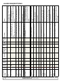
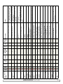
1
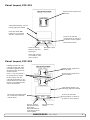
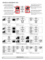
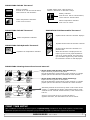
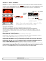
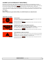
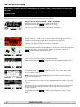
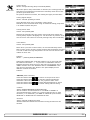
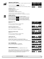
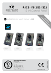
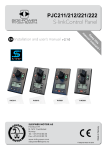
SIDE-POWER PJC211/212/221/222 S-link Control Panel Thruster Systems Installation and user's manual v 2.0.3 is rd th a p bo ee n K al o u an m ! SLEIPNER MOTOR AS P.O. Box 519 N-1612 Fredrikstad Norway Tel: +47 69 30 00 60 Fax: +47 69 30 00 70 w w w. s i d e - p o w e r. c o m s i d e p o w e r @ s l e i p n e r. n o Made in Norway EN © Sleipner Motor AS 2014 CONTENTS Product Features.................................................................................................................................................................................. 3 Panel layout ......................................................................................................................................................................................... 4 Panel layout ......................................................................................................................................................................................... 5 Display in normal use .......................................................................................................................................................................... 6 Display when alarms............................................................................................................................................................................ 7 Setup procedure................................................................................................................................................................................... 8 Menu system........................................................................................................................................................................................ 9 Alarm descriptions ............................................................................................................................................................................. 16 S-link system example....................................................................................................................................................................... 18 Measurements / Cut-out template...................................................................................................................................................... 19 Connections for external buzzer......................................................................................................................................................... 19 DO NOT connect any other control equipment to the S-link controlled products except Side-Power original S-link products or via a Side-Power supplied interface product made for interfacing with other controls. Any attempt to directly control or at all connect into the S-link control system without the designated and approved interface, will render all warranties and responsibilities for the complete line of Side-Power products connected void and null. If you are interfacing by agreement with Sleipner and through a designated and approved interface, you are still required to also install an original Sidepower control panel to enable efficient troubleshooting if necessary DECLARATION OF CONFORMITY We, Sleipner Motor AS P.O. Box 519 N-1612 Fredrikstad, Norway declare that this product with accompanying standard remote control systems complies with the essential health and safety requirements according to the Directive 89/336/EEC of 23 May 1989 amended by 92/31/EEC and 93/68/EEC. 2 PJC211/212/221/222 2.0.3 - 2014 PJC-211/212/221/222 Control panel with S-link™ CAN-bus connection Product features • For proportional thruster control with DC, AC and Hydraulic Thrusters (Hydraulic thrusters PJC-221/222 only). • Finger tip control speed control with purpose designed joysticks • Hold - function for easy docking, runs thrusters at selected power (Dual joysticks PJC-212/222 only) • Back-lit LCD display with instant feedback - System status / alarms - Amount of thrust & direction of thrust • Interactive multi-language menus • CAN-Bus communication with thrusters and accessories • Plug & play cables with compact connectors • Diagnostics and system setup via panel • Built-in audible alarm “buzzer” • Connector for external “buzzer”/loud audible alarms • Supports Side-Power retractable thrusters with or without Speed Control PJC211/212/221/222 2.0.3 - 2014 3 Panel Layout, PJC-211 Speed control joystick for thruster Information display, see following pages for details. Press both “ON” buttons simultanously to activate control panel. MENU Press to de-activate control panel or cancel or go back in menu system or mute internal alarm buzzer MENU Press to change Press and hold for 3 between day and seconds to access menu night light system and choose items in menus Panel Layout, PJC-212 Holding function for autorunning of bow and stern thrusters together in the direction of the arrows at selected power Speed control joystick for bow thruster Speed control joystick for stern thruster Press “+” for more and “-” for less power (6 steps). If any control unit are running the thruster in opposite direction to the hold function, the hold function will be deactivated. Information display, see following pages for details. Press both “ON” buttons simultaneously to activate control panel. Press to de-activate control panel or cancel or go back in menu system or mute internal alarm buzzer MENU Press to change Press and hold for 3 between day and seconds to access night light menu system and choose items in menus 4 PJC211/212/221/222 2.0.3 - 2014 Panel Layout, PJC-221 front s_v strek_PJC222.pdf 1 04.11.2010 11:05:34 Speed control joystick for thruster Information display, see following pages for details. Press and hold “ON” button for 1 second to activate control panel. Press to de-activate control panel or cancel or go back in menu system. MENU STOP Mute buzzer alarm Press to change between day and night light. Emergency stop button Press and hold for 3 seconds to enter menu system Panel Layout, PJC-222 front s_v strek_PJC222.pdf 1 04.11.2010 11:05:34 Holding function for autorunning of bow and stern thrusters together in the direction of the arrows at selected power Speed control joystick for bow thruster Speed control joystick for stern thruster Press “+” for more and “-” for less power (6 steps). If any control unit are running the thruster in opposite direction to the hold function, the hold function will be deactivated. Information display, see following pages for details. Press and hold “ON” button for 3 seconds to activate control panel. Press to de-activate control panel or cancel or go back in menu system STOP Press to change between day and night light. Press and hold for 3 seconds to enter menu system Emergency stop button PJC211/212/221/222 2.0.3 - 2014 5 DISPLAY IN NORMAL USE: Status indicators for bow thruster. (Port bow thruster in a dual bow thruster setup) BOW BOW-STB Status indicators for starboard bow thruster. Only shown in a dual bow thruster setup. Runtime indicator will be shown here in a single DC electric bow thruster setup Battery indicator will be shown here in a single DC electric bow thruster setup Status indicators for stern thruster. (Port bow thruster in a dual stern thruster setup) Status indicators for starboard stern thruster. Only shown in a dual stern thruster setup. Runtime indicator will be shown here in a single DC electric stern thruster setup STERN STERN-STB Battery indicator will be shown here in a single DC electric stern thruster setup. Examples of display for different panel applications: PJC211/221: DC Electric Bow thruster PJC221: Hydraulic Bow thruster PJC221: AC Electric Bow thruster PJC212/222: DC Electric Bow thruster DC Electric Stern Thruster PJC222: Hydraulic Bow thruster Hydraulic Stern Thruster PJC222: AC Electric Bow thruster Hydraulic Stern Thruster PJC211/221: DC Electric Stern thruster PJC212/222: Dual DC Electric Bow thrusters Dual DC Electric Stern thrusters PJC222: Dual Hydraulic Bow thrusters Dual Hydraulic Stern thrusters PJC222: Dual AC Electric Bow thrusters Dual AC Electric Bow thrusters PJC221: Dual AC Electric Bow thrusters PJC221: Dual Hydraulic bow thrusters 6 PJC211/212/221/222 2.0.3 - 2014 INDICATORS FOR DC Thrusters: Battery indicator. From 8.5V to 12V for 12V thrusters, 15V to 24V for 24V thrusters Symbol shown when a DC Thruster is used in a dual bow or dual stern setup: Battery indicator. From 8.5V to 12V for 12V thrusters, 15V to 24V for 24V thrusters Motor temperature indicator. From 70°C to 130°C INDICATORS FOR AC Thrusters: Motor temperature indicator. From 70°C to 130°C INDICATORS FOR Retractable Thrusters: Symbol shown when the thruster deploys Motor temperature indicator. Symbol shown when the thruster retracts INDICATORS FOR Hydraulic Thrusters: Symbol shown when the thruster is in position OUT Hydraulic oil temperature indicator. When the thruster is deployed and no input is given via the joysticks/buttons over a 10 second period, the panel will give a audible signal every 10th second to tell that the truster is still deployed. INDICATORS showing thrust direction and amount: Thrust power and direction, Bow thruster(s) Input from bow joystick on this panel. The thrust indicator will be shown in this position on a single joystick panel if the thruster is defined as a bow thruster Thrust power and direction, Stern thruster(s) Input from stern joystick on this panel The thrust indicator will be shown in this position on a single joystick panel if the thruster is defined as a stern thruster. Indicating amount of thrust set by other control units in the system, i.e additonal PJC panels, 8700 Retract panel, input via 8730 S-link external switch interface, S-link remote control etc. If two or more units is set to run the thruster in opposite direction, this information will not be shown. FIRST TIME SETUP After installation of a S-link thrusters system, a System Setup procedure to setup control panels, thrusters and additional equipment must be completed (ref. procedure on page 10) before the system can be used. PJC211/212/221/222 2.0.3 - 2014 7 DISPLAY WHEN ALARMS: When there is a problem or a fault, the panel will show this alarm situation by changing LCD display backlight to red color. The panel will also change to show “Alarm Info” on the bottom of the screen, indicating that by pressing the corresponding button below, you will get information about what the problem is (examples below). Alarm code Name and location of device No. of alarms Alarm description Scroll bar MENU (Button below this symbol pressed) Use joystick to scroll if more than two alarms STOP Reset alarm and Return Refer to Alarm code overview/table on pages 18-19 for full description on the different alarm codes. Non auto reset alarms Some alarms is not auto reset, and needs an confirmation from user to be reset. This alarms need reset: Motor Overcurrent 1, Controller Overtemp 2, Low Voltage 5, IPC Error 7, Critical Error 8, Low Motor Current 9, Motor Contactor 10, System Error 11, No Communication 12, Motor Temp Sensor 13, Supply Voltage Fault 14, Fuse Blown 15, Motion OUT Fault 17, Motion IN Fault 18, Actuator Fault 19, Pos.Sensor Fault 20, Low Oil Level 23, AC Motor Sensor Fault 29, VFD Fault 34, Warning Low Voltage 35. When using the “HOLD” function, the internal and external (if fitted) buzzer will give the following warning signals: Voltage below 9.3V/17.5V (12V/24V system) or temperature above 85oC (80oC for PPC800 FW V1.013 or older/ SR150000 FW V1.006 or older): Single short beep every 2.4 seconds Voltage below 8.9V/16.3V (12V/24V system) or temperature above 100oC (90oC for PPC800 FW V1.013 or older/ SR150000 FW V1.006 or older): Two short beeps every 2.4 seconds Voltage below 8.5V/15V (12V/24V system) or temperature above 115oC (100oC for PPC800 FW V1.013 or older/ SR150000 FW V1.006 or older): Red backlight in display and continous short beeps. If one or more of the thrusters enters an alarm state - Voltage below 8 Volts (both 12 and 24 Volt systems) or temperature above 130oC (110oC for PPC800 FW V1.013 or older/ SR150000 FW V1.006 or older): Continuous beeps, and the “HOLD” function will be cancelled and both thrusters will stop. Temperature must drop below 115oC (100oC for PPC800 FW V1.013 or older) before the thruster can be operated again. 8 PJC211/212/221/222 2.0.3 - 2014 ALARMS (AC & HYDRAULIC THRUSTERS): When there is a problem or a fault, the panel will show this alarm situation by the LCD display in red color. All alarms will show in display when panel is turned OFF. This requires the S-link and other system devices has power. Critical alarms are also trigging internal and external buzzer (a long beep every 2 seconds). The buzzer can be silenced by pushing the button below , this will also silence all other panels in the system Critical alarms: LOW OIL LEVEL, HIGH OIL TEMPERATURE, EMERGENCY STOP, HIGH SPEED STABILIZER NOT ACTIVE and HYDRAULIC AC MOTOR POWER PACK OVERTEMP, AC THRUSTER OVERTEMP, AC THRUSTER FAIL, STABILIZER FAULT For safety! When oil pressure goes below 10bar, the HOLD function are deactivated. SPECIFIC ALARMS STOP BUTTON Pressing the STOP button on a hydraulic panel will operate the dump valve and the thruster will stop. NB: FOR EMERGENCY USE ONLY Panel will not run thrusters. Pressing button below the alarm info screen. will mute buzzer alarm at all panels and show WARNING! HIGH SPEED. STABILIZER NOT ACTIVE! (Only for yachts equipped with a Side-Power Stabilizer system) Warning will show when yacht is driven at high speed with stabilizer system inactive. Please refer to the Stabilizer ECU manual for speed settings. Pressing button below the alarm info screen. will mute buzzer alarm at all panels and show ALARM SHOWN ON INACTIVE PANELS! This screen will be shown on inactive panels if any of the following critical alarms occur: LOW OIL LEVEL, HIGH OIL TEMPERATURE, HYDRAULIC AC MOTOR POWER PACK OVERTEMP, AC THRUSTER OVERTEMP, AC THRUSTER FAIL Pressing button below the alarm info screen. PJC211/212/221/222 will mute buzzer alarm at all panels and show 2.0.3 - 2014 9 SETUP PROCEDURE The setup procedure requires knowledge of the serial numer and location of all the S-link devices. Write this down in the form on the last page to have the information at hand when doing a manual setup. At the first startup of a new system, one of the two screens below will be shown: SETUP DO NOT MATCH SYSTEM. FOR AUTO SETUP New devices found. Not in conflict with other devices. Press button below the -symbol to auto setup. Thrusters can not be operated to auto setup is completed. RUN SETUP! DEVICES IN CONFLICT! Detectet devices in conflict. Two or more thrusters defined as same instance (bow/stern/bow STB/Stern STB). Run Setup procedure to correct. Thrusters can not be operated until seup is completed. Press and hold the button marked “MENU” for 3 seconds to enter the menu system. Use the (stern) joystick to select “SETUP”, Press button below the -symbol to enter the”SETUP”-menu. Use the (stern) joystick to select “SYSTEM DEVICES”, -symbol to enter the”SYSTEM DEVICES”-menu. Press button below the Use the (stern) joystick to set the pin code one number at the time, press button below the -symbol to jump to next number and confirm. The pin code is “9 9 9 9”. NOTE: Re-entering the SYSTEM DEVICES menu within 15 minutes does not require entering PIN code The devices found in the system is now displayed with their instance and serial number. Go through all devices and make sure that they are set to the correct instance and function (refer to detailed instructions in the SETUP section of “Menu System”-chapter). Press button below the Menu. 10 PJC211/212/221/222 -symbol to save setting and return to “Setup”- 2.0.3 - 2014 MENU SYSTEM: front s_v strek_PJC222.pdf 1 04.11.2010 11:05:34 Access menu system by press and hold Menu button for 3 seconds Move around in menus by using joysticks Follow instructions on the screen and press the buttons below the symbols indicated on LCD screen STOP MENU MAIN MENU ITEMS: Move between main menu items with the (stern) joystick. BUTTON SYMBOLS On the bottom line of the display, a symbol will be shown over the buttons below. These symbols will show what function each corresponding button have in the selected menu entry. : : : : Return to previous menu. Select highlighted menu text / Save edited parameter. Edit highlighted parameter. Cancel editing without saving. : This symbol indicates that the (stern) joystick is used to move between menu items /parameters. LANGUAGE LANGUAGE Choose language by moving joystick: English, Norwegian, German, French, Spanish and Italian. Press the button below to set the language to the highlighted menu entry. A star (*) on each side indicated the laguage set. STABILIZER (Shown only for yachts equipped with a Side-Power Stabilizer system) STABILIZER (Default in systems with stabilizers) to edit the selected parameter. Press the button below ON/OFF will start to blink, use joystick to alter value. Press the button below to save edited parameter to device. STABILIZER: Values: ON/OFF Switches the stabilizer ON or OFF. AnySpeed: Values: ON/OFF Switches the zero speed/at anchor stabilization ON or OFF. PJC211/212/221/222 2.0.3 - 2014 11 SETUP SETUP (Default in systems without stabilizers) Move between menu items with the (stern) joystick. Press the button below to select the highlighted menu entry. Press the button below to return to the previous menu. Setting done under SETUP will be sent to all other panels in the system. SYSTEM DEVICES View all devices (except PDC1001) connected to S-Link and manually change setup values. 1 PDC100 must be setup by authorized personnel. A PIN code is required to enter the SYSTEM DEVICES menu. Use the (stern) joystick to set the pin code one number at the time, press button below the -symbol to jump to next number and confirm. The pin code is “9 9 9 9”. The number of devices found is shown in the upper right corner of the display. Use (stern) joystick to move between the installed devices. The list of devices found can fill more than one screeen. A scroll bar indicates the position of the selected item. NOTE: Re-entering the SYSTEM DEVICES menu within 15 minutes does not require entering PIN code PHC 024 (Controller for hydraulic thrusters) Most functions requires PHC 024 with firmware V.1.101 or newer! Move between PHC-024 parameters with the (stern) joystick. Press the button below to return to the previous menu. to edit the selected parameter. Press the button below Parameter value will start to blink, use joystick to alter value. Press the button below to save edited parameter to device Press the button below to cancel editing without saving. Bow/Stern Direction: Values: Normal (default)/Inverted Switches between Normal and Inverted running direction for the thruster Pump Control (PTO Mounted Pump) Values: Auto(default)/Always ON When «Pump Control» is set to «Auto», the system will automatically control load sharing between two PTO pumps by deactivating the second PTO pump when not needed (two PTO pumps/control valves required) to reduce heat generation in the system and save fuel/energy. When any thruster is running, both PTO pumps will be active to ensure good performance. When a SPS stabilizer system is active, one PTO pump will be deactivated to save power. If stabilizers are active and the system pressure drop below 80bar, the system will activate the second PTO pump for 15 minutes to increase the flow capacity and maintain required pressure. After 15 minutes the second pump will be deactivated unless the pressure is still below 80 bar. NB: “Pump Control: Auto” must only be used on PHC 024 with firmware V.1.008 or newer! 12 PJC211/212/221/222 2.0.3 - 2014 Cooling Pump Values: Always Running/Temp Controlled(default) SETUP cont. When the option “Temp Controlled” is selected, the cooling pump will start when oil temperature exceeds 50°C and stop when the oil temperature goes below 40°C. On systems with two oil tanks, this setting will apply to both tanks. Cooling Signal Output Values: Normal (default)/Inverted Set to Normal when using a hydraulic cooling pump. Should be set to Inverted when using an electrical cooling pump with a 10 2380A-12/24V relay box Cooling Power Save Values: ON (default)/OFF ON sets the Cooling Pump into power save mode,which means the Cooling Pump output is dropping to 0 volt when the oil pressure is below 10 bar for more than 10 seconds (Cooling Pump are turned OFF). Tank Monitor Values: ON (default)/OFF ON is when you have a tank monitor, oil level and Oil temp sensor. OFF is when you do not have a tank monitor and the display will show 0°C and no alarm for high temperature or low level will not be transmitted on the S-link. Instance Values: --(default)/PORT/STARBOARD Setting the PHC024 tank controller instance. For a mono hull boat the instance should be ”--“. If you have an catamaran with two PHC024 controllers then the one in the port hull should be set as “PORT” and the one in the starboard hull as “STARBOARD”. This way the two controllers are shown in the panel display as two different oil tanks to monitor. Instance PDC 201 (SAC Controller) to return to the previous menu. Press the button below Press the button below to edit the selected parameter. Parameter value will start to blink, use joystick to alter value. Press the button below to save edited parameter to device Press the button below to cancel editing without saving. Location Values: BOW/STERN/BOW-STB/STERN-STB Set the location for selected device. Use BOW or STERN in a conventional thruster system. In a system with two bow or stern thrusters (i.e a catamaran), use BOW or STERN for port thruster, BOW-STB or STERN-STB for starboard thruster Direction Values: Normal (default)/Inverted Switches between Normal and Inverted running direction for the thruster PJC211/212/221/222 2.0.3 - 2014 13 SETUP cont. Main Switch Press the button below to return to the previous menu. Press the button below to edit the selected parameter. Parameter value will start to blink, use joystick to alter value. Press the button below to save edited parameter to device Press the button below to cancel editing without saving. Location Values: BOW/STERN/BOW-STB/STERN-STB Set the location for selected device. Use BOW or STERN in a conventional thruster system. In a system with two bow or stern thrusters (i.e a catamaran), use BOW or STERN for port thruster, BOW-STB or STERN-STB for starboard thruster PPC800 (DC Speed Control) SR150000 (Control unit for SRV80/SRV100/SRV130/SRV170/SRV210/SRH) SR61242 (Control unit for SR80/SR100) Move between parameters with the (stern) joystick. to return to the previous menu. Press the button below Press the button below to edit the selected parameter. Parameter value will start to blink, use joystick to alter value. to save edited parameter to device Press the button below Press the button below to cancel editing without saving. Location Values: BOW/STERN/BOW-STB/STERN-STB Set the location for selected device. Use BOW or STERN in a conventional thruster system. In a system with two bow or stern thrusters (i.e a catamaran), use BOW or STERN for port thruster, BOW-STB or STERN-STB for starboard thruster Direction Values: Normal (default)/Inverted Switches between Normal and Inverted running direction for the thruster Function Values: SR(V/L) ON/OFF, SRP 80/100, SRVP 130-210, SEP 30-240, SRVP 80/100, SRH, SRHP Setup the control unit behaviour SR(V) ON/OFF: Retract thruster without speed controller (PPC800/PHC-024), SR61242 or SR150000. SEP 30-240: Tunnel speed thruster, PPC800 without retract. SRP: Retract SR61242 with PPC800, both devices needs to be set to SRP 80/100. SRVP/SRLP: Retract SR150000 with PPC800, both devices needs to be set to SRVP/SRLP. SRHP: Proportional Hydraulic retract. This needs the PHC024 controller. PPC800 SR(V/L ) ON/OFF SRP SRVP/SRLP SEP 30-240 SRHP 14 x x x SR150000 x SR61242 x x PHC 024 x x PJC211/212/221/222 x 2.0.3 - 2014 SETUP cont. RCRS-1 (S-Link Radio Remote Receiver) Move between parameters with the (stern) joystick. Press the button below to return to the previous menu. Press the button below to edit the selected parameter. Parameter value will start to blink, use joystick to alter value. Press the button below to save edited parameter to device Press the button below to cancel editing without saving. BOW/STERN Thrust Values: 0-100% (Default 75%) Set the amount of thrust given by the remote control. In a bow/stern configuration, try to balance the thrust so that the boat moves straight sideways when both thrusters are operated simultanously with input from the remote only. MSI8730 (S-Link Interface) Move between parameters with the (stern) joystick. Press the button below to return to the previous menu. Press the button below to edit the selected parameter. Parameter value will start to blink, use joystick to alter value. Press the button below to save edited parameter to device Press the button below to cancel editing without saving. Location Values: BOW/STERN/BOW-STB/STERN-STB Set the location for selected device. Use BOW or STERN in a conventional thruster system. In a system with two bow or stern thrusters (i.e a catamaran), use BOW or STERN for port thruster, BOW-STB or STERN-STB for starboard thruster Thrust Values: 0-100% (Default 75%) Set the amount of thrust given by the remote control. In a bow/stern configuration, try to balance the thrust so that the boat moves straight sideways when both thrusters are operated simultanously with input from the remote only. HOLD CALIBRATION Calibrates the HOLD-function to get balanced thrust from the bow and stern thruster. To start calibration, press the “+”-Hold button in the desired direction. For a first time calibration, the thrusters will start at 70%. A system previously calibrated will start with the last amount of thrust set. One step on the Hold-button represents 1/6 if the calibrated value. Adjust power with the joystick. to save the calibration values. Press the button below Press the button below to cancel calibration without saving. PJC211/212/221/222 2.0.3 - 2014 15 INFO INFO Move between menu items with the (stern) joystick. Press the button below to select the highlighted menu entry. Press the button below to return to the previous menu. THRUSTER INFO Display info about the thusters in the system The number of thrusters/controllers found is shown in the upper right corner of the display. Use (stern) joystick to move between the installed devices. to select the highlighted menu entry. Press the button below to return to the previous menu. Press the button below The list of devices found can fill more than one screeen. A scroll bar indicates the position of the selected item. The joystick(s) operates the thrusters as normal while info is displayed, this will be useful for troubleshooting, service and general system diagnostics. PPC800 (DC Speed Control) SR150000 (Control unit for SRV80/SRV100/SRV130/SRV170/SRV210/SRH) SR61242 (Control unit for SR80/SR100) Motor Temp: Temperature measured at the electric motor brushes (Not implemented in SR61242) Contr. Temp: Temperature measured inside the controller (Not implemented in SR61242) Voltage: Motor Voltage measured at the controller Thrust: Thrust level from joystick/hold buttons A/kW: Motor Current and Effect reading measured at the controller (PPC800 only) Press the button below to return to the previous menu. PHC024 (Controller for hydraulic thrusters) Oil Pressure: Oil pressure measured at system oil tank Oil Temp: Temperature measured inside the oil tank Bow Thrust: Thrust level from joystick/hold buttons Stern Thrust: Thrust level from joystick/hold buttons FW: Version number, Firmware S/N: Serial number of the PHC 024 Press the button below to return to the previous menu. PDC100 (Controller for AC electric thrusters) Motor Speed: RPM on motor output shaft Motor Temp: Temperature measured in motor Thrust: Thrust level from joystick/hold buttons Press the button below to return to the previous menu. Panel INFO Display info about the control panel FW: Version number, Firmware HW: Version number, Hardware S/N: Serial number of the control panel Voltage: S-link system voltage measured at the panel Press the button below 16 to return to the previous menu. PJC211/212/221/222 2.0.3 - 2014 DEFAULT SETTINGS Reset all settings to factory default - follow instructions on screen DEFAULT Press the button below to confirm reset The following parameters/values will be set to the factory settings: Language = English Backlight Level = 5 Backlight Night Color = Green Backlight Nightlevel =1 Timer Auto-Off = 05 min Hold Calibration =70% Bow and Stern All system devices will be erased from memory. (Setup procedure must be followed to reconfigure the system) PANEL SETUP PANEL Move between parameters with the (stern) joystick. Press the button below to return to the previous menu. Press the button below to edit the selected parameter. Parameter value will start to blink, use joystick to alter value. to save the edited parameter. Press the button below Press the button below to cancel editing without saving. BACKLIGHT LEVEL Values: 1-5 Set level of panel backlight in daylight mode. 1 is lowest intensity, 5 is the highest. BACKLIGHT NIGHT COLOR Values: GREEN, BLUE, RED, WHITE Select color of backlight in nightlight mode BACKLIGHT NIGHT LEVEL Values: 1-3 Set level of panel backlight in daylight mode, 1 is lowest intensity, 3 is the highest. TIMER AUTO-OFF Values: OFF, 01-60 min Set the time from last use to auto panel shutdown. Set from 1-60 minutes in 5 minute steps (1 minute steps from 1 to 5 minutes) or OFF (panel will not turn off automatically) UNIT TEMPERATURE Values: CELSIUS (Default), FAHRENHEIT Set the panel temperature displaying unit WHEN RETRACT IS OUT Values: NO WARNING (Default), WARNING EVERY 10sec Select ‘WARNING EVERY 10sec’ for external buzzer or lamp warning every 10 secondswhen retract is out. This will activate the internal relay for 0.2 seconds every 10 seconds while the retract is out. See page 22 for buzzer connections. PJC211/212/221/222 2.0.3 - 2014 17 18 2 Yes 3 Motor Overtemp Controller Overtemp Controller Overtemp Low Voltage X PJC211/212/221/222 X X 2.0.3 - 2014 Manual Override Motion OUT Fault Motion IN Fault X X 17 18 X X 15 16 Yes X 14 X X X X X X X 13 X X Retract obstructed while retracting Retract obstructed while deploying Main switch manually overridden Fuse blown No power Motor temperature sensor fail No communication with device Fatal error 12 X No Communication Motor Temp Sensor Supply Voltage Fault Fuse Blown X X 11 System Error Motortemp have been over 110°C Motor relay fault SR150000 temp have been over 80°C Low voltage on Motor Turn off all panels. Go for lower speed/deeper water and retry. Turn panel on and manually override main switch. Remove obstruction and try again. Replace fuse or check if main cable from battery and main cable to thruster has been switched Pull main switch Check for an open circiut on the temp sensor on the motor Check power connections Recharge battery, reset or device power OFF/ON Motor cool down below 100°C Turn off thruster battery main switch. Thruster must be serviced by authorized personel, power OFF resets alarm. PPC800 must be sendt for service Check thruster connections or motor dead! Check motor relay connections, short circuit or relay dead! Device must be serviced by authorized personel Check S-Link or power connections SR150000 cool down below 45°C PPC800 temp have been over 80°C PPC800 cool down below 45°C No current on motor relay coil. X X Action Thruster must be serviced by authorized personel, reset or PPC800 power OFF/ON Motor cool down below 115°C Motortemp have been over 130°C (100°C for PPC800 FW V1.013 and (110°C for PPC800 FW V1.013 or older older and SR150000 FW V1.006 and and SR150000 FW V1.006 or older.) older) Motorcurrent over 1400A Stabilizer Description ECU X X X SAC PPC800 output fail Thruster uses no power X PHC 024 X X 6 Yes 7 X X 5 X SRV130-210 SRV80/100 SRH X X SR80/100 4 X X AMS 8977 Critical Error 8 Low Motor Cur- 9 rent Motor Contactor 10 Thermoswitch IPC Error 1 Motor Overcurrent X Err. Auto PPC No. Reset 800 Errors shown in display ALARM DESCRIPTIONS PJC211/212/221/222 2.0.3 - 2014 19 X X 31 Yes 32 Yes VFD Not Ready 33 Yes 34 35 VFD Warning VFD Fault Warning Low Voltage Not Calibrated VFD Modbus Fault X X 25 Yes 37 36 Yes 30 Yes 29 X X X X X X X X 27 Yes 28 Yes X X 26 Yes X X 24 Yes Warning Return Filter Warning Pressure Filter Warning High Speed Stabilizer Fault AC Motor Overtemp AC Motor Sensor Fail Temperature Warning Motor Overtemp X 23 Yes PDC201 no Modbus communication Drive shaft not aligned Return filter element requiered replacing Pressure filter element requiered replacing WARNING! High Speed. Stabilizer not active! Any Stabilizer alarm. Hydraulic AC motor power pack overtemp. Higher than 120°C Hydraulic AC motor power pack temp sensor open curicuit High temperature warning. Se manual for more details. High temperature Alarm. Se SAC manual for more details. There is an warning from VFD. Check VFD for more details. The VFD is not ready. Check VFD for more details. VFD has an Alarm. Check VFD for more details. Low voltage Warning! Hydraulic oil lewel is to low Hydraulic oil temperature is higher than 75°C Retract controller in service mode Actuator not getting any power Stabilizer Description ECU X X SAC Retract position sensor fail X PHC 024 X X SRV130-210 SRV80/100 SRH Low Oil Level X SR80/100 22 Yes AMS 8977 High Oil Temp X 19 Actuator Fault Pos.Sensor 20 Fault In Service Mode 21 Yes Err. Auto PPC No. Reset 800 Errors shown in display Calibrate drive shaft alignment, see retract manual Se stabilizer panel for more info. Check actuator connection or power to actuator. Reset alarm in alarm menu on PJC 2xx or recycle power Check position sensor cables and for sensor damage. Check dipswitch setting on retract control box. Stop running and wait for temperature to drop. Check if cooling pump is running. Fill more hydraulic oil to the hydraulic tank. Action 20 PJC211/212/221/222 Bow thruster (SEP model) Proportional Power Controller End terminator S-link external switch interface and remote (optional) PPC 2.0.3 - 2014 +12/24 5A - black + red B+ Automatic Main Switch 8977 12 / 8977 24 or Manual main switch w/ANL fuse Fixed multicable 5m S-link external switch interface and remote (optional) 8730 Bow thruster battery 12/24V - S-link supply +12/24V 5A S-link on/off switch red Stern thruster battery 12/24V - 5A +12/24 Automatic Main Switch 8977 12 / 8977 24 or Manual main switch w/ANL fuse + red B+ black Observe PPC battery terminal polarity ! S-link control system Station 1 Proportional joystick control panel Bow and stern yellow black 8730 PJC 212 PPC Station 2 Proportional joystick control panel Bow and stern Stern thruster (SEP model) Fixed multicable 5m Proportional Power Controller End terminator PJC 212 Sample S-link system Measurements PJC211/212/221/222 2.0.3 - 2014 21 Connections for optional external buzzer/audible alarm External alarm/buzzer connection (S-link) Re a of r sid pa ne e l Internal fuse/relay + External alarm buzzer 12V / 24V DC - max 0,5A 22 PJC211/212/221/222 2.0.3 - 2014 Supply +12V / 24V DC Fill in the type, location and serial numbers of the S-link devices installed. Keeping this as a reference will make the setup procedure easier! S-link device Location (ie Thruster, AMS, PPC800 etc) (Bow, Bow-STB, Stern, Stern-STB) PJC211/212/221/222 Serial number 2.0.3 - 2014 23 SIDE-POWER SERVICE CENTRES Argentina Trimer SA Buenos Aires Tel:+54 11 4580 0444 Fax:+54 11 4580 0440 www.trimer.com.ar [email protected] Estonia/Latvia/Lithuania Miltec Systems OÜ Tallin Tel: +372 5013997 Fax: +372 6442211 www.miltec.ee [email protected] Japan Turtle Marine Inc. Nagasaki Tel:+81 95 840 7977 Fax:+81 95 840 7978 www.turtle-marine.com [email protected] Spain Imnasa Marine Products Girona Tel:+34 902 300 214 Fax:+34 902 300 215 www.imnasa.com [email protected] Australia AMI Sales Freemantle, WA Tel:+61 89 331 0000 Fax:+61 89 314 2929 [email protected] Finland Side-Power Europe Vaasa Tel: +358 6 317 10 41 Fax: +358 6 317 10 42 [email protected] Austria G. Ascherl GmbH Hard, Bregenz Tel:+43 5574 899000 Fax:+43 5574 89900-10 www.ascherl.at [email protected] France Kent Marine Equipment Nantes Tel:+33 240 921 584 Fax:+33 240 921 316 www.kent-marine.com [email protected] Malta S & D Yachts Ltd. Cali Tel:+356 21 339 908 Fax:+356 21 332 259 www.sdyachts.com [email protected] Sweden Sleipner AB Strömstad Tel:+46 526 629 50 Fax:+46 526 152 95 www.sleipnerab.se [email protected] Benelux ASA Boot Electro Watergang Tel:+31 20 436 9100 Fax:+31 20 436 9109 www.asabootelectro.nl [email protected] Germany Side-Power Europe Tel:+49 7159 4 59 0761 www.side-power.com [email protected] New Zealand Advance Trident Ltd. Auckland Tel:+64 9 845 5347 Fax:+64 9 415 5348 www.advancetrident.com [email protected] Switzerland Senero AG Winterthur Tel:+41 52 203 66 55 Fax:+41 52 203 66 56 www.senero.ch [email protected] Norway Sleipner Motor AS Fredrikstad Tel:+47 69 30 00 60 Fax:+47 69 30 00 70 www.sleipner.no [email protected] Singapore/Malaysia/ Indonesia/ Vietnam/Phillipines/Thailand Island Marine Services Pte Ltd Singapore Tel:+65 6795 2250 Fax:+65 6795 2230 www.island-marine.com [email protected] Brazil Electra Service Ltda. Guaruja Tel:+55 13 3354 3599 Fax:+55 13 3354 3471 www.electraservice.com.br [email protected] Bulgaria Yachting BG Burgas tel: +359 56 919090 fax: +359 56 919091 www.yachting.bg [email protected] China/Hong Kong Storm Force Marine Ltd. Wanchai, Hong Kong Tel:+852 2866 0114 Fax:+852 2866 9260 www.stormforcemarine.com [email protected] Croatia Yacht Supplier Icici Tel:+385 51 704 500 Fax:+385 51 704 600 [email protected] Cyprus Ocean Marine Equipment Ltd Limassol Tel: +357 253 69731 Fax: +357 253 52976 [email protected] Denmark Side-Power Europe Tel: +45 53 58 93 63 www.side-power.com [email protected] Greece Amaltheia Marine Athens Tel:+30 210 2588 985 Fax:+30 210 2588 986 www.amaltheiamarine.com [email protected] Iceland Maras EHF Reykjavik Tel:+354 555 6444 Fax:+354 565 7230 www.maras.is [email protected] India Indo Marine Engineering Co. Pvt. Ltd Pune, Maharashtra Tel:+91 20 2712 3003 Fax:+91 20 2712 2295 [email protected] Israel Atlantis Marine Ltd. Tel Aviv Tel:+972 3 522 7978 Fax:+972 3 523 5150 www.atlantis-marine.com [email protected] Italy Saim S.P.A. Assago-Milan Tel:+39 02 488 531 Fax:+39 02 488 254 5 www.saim-group.com Poland Taurus Sea Power SP. Z.O.O Gdansk Tel:+48 58 344 30 50 Fax:+48 58 341 67 62 www.taurus.gda.pl Taiwan Mercury Marine Supply Kaohsiung Tel:+886 7 3317 293 Fax:+886 7 3314 232 Portugal Riesnautica Lda. Alhos Vedros Tel:+351 210 865 077 www.riesnautica.pt [email protected] Turkey Denpar Ltd. Istanbul Tel:+90 212 346 1332 Fax:+90 212 346 1329 [email protected] Russia Standarte Starbeyevo Tel:+7 495 575 67 23 Fax:+7 4 95 575 39 77 www.standarte.ru [email protected] UK/Ireland Sleipner Motor Ltd. South Brent Tel:+44 1364 649 400 Fax:+44 1364 649 399 [email protected] South Africa PowerSol Cape Town Tel: +27 21 552 1187 Fax: +27 21 555 2503 [email protected] South Korea D-I Iindustrial Co Ltd Jinju-si, Kyungnam-do Tel: +82 55 760 5520 Fax: +82 55 755 9188 www.d-i.co.kr [email protected] Sleipner Motor AS • P.O. Box 591, N1612 Fredrikstad • Norway Tel: +47 69 30 00 60 • Fax: +47 69 30 00 70 [email protected] • www.side-power.com Ukraine Yachtglanz Marine Equipment Tel:+49 231 474 09 599 Fax:+49 231 474 11 594 www.yachtglanz.com [email protected] United Arab Emirates Teignbridge Propellers & Marine Equipment Co. Ltd. Dubai Tel:+971 4 324 0084 Fax:+971 4 324 0153 [email protected] USA/Canada/Carribean Imtra Corporation New Bedford, MA Tel:+1 508 995 7000 Fax:+1 508 998 5359 www.imtra.com [email protected]