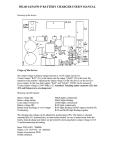
1
Hydra 2000 User Manual
Part 3 - Calibration
PART 3 - CALIBRATION
CONTENTS
Para
Page
3.1
INTRODUCTION
3-3
3.2
3.2.1
3.2.2
3.2.3
3.2.4
3.2.5
3.2.6
3.2.7
3.2.8
BOAT SPEED/LOG CALIBRATION
Principle of Log Calibration
Preparation for Log Calibration
Calibration Runs
Log AUTO CAL Facility
Log AUTO CAL Procedure
Manual Calibration
Boat Speed Calibration (ref. to a Known Value)
Boat Speed Calibration (Knots, MPH, KPH)
3-4
3-4
3-4
3-4
3-5
3-6
3-7
3-7
3-8
3.3
APPARENT WIND SPEED/ANGLE
CALIBRATION
Principles of Wind Speed/Angle Calibration
Apparent Wind Angle Calibration (AWA)
Apparent Wind Speed Calibration
3-9
3-9
3-10
3-11
3.3.1
3.3.2
3.3.3
3.4
3.4.1
3.4.2
3.4.3
3.4.4
3.4.5
3.4.6
3.4.7
COMPASS CALIBRATION
3-12
Principles of Compass Calibration
(Super Halcyon 3 & Halcyon 2000 Compasses) 3-12
Heading Node Selection
3-13
Super Halcyon 3 Compass Calibration Procedure3-14
Halcyon 2000 Calibration Procedure
3-15
Halcyon Gyro Stabilised Calibration Procedure 3-16
Halcyon Processor Setup
3-18
Halcyon Processor NMEA Output
3-18
3.5
3.5.1
3.5.2
3.5.3
HEEL ANGLE/LEEWAY CALIBRATION
Heel Angle Calibration
Leeway Calibration
Heel and Trim Angle with the Halcyon Gyro
Stabilised Compass
3-19
3-19
3-19
3-21
3.6
3.6.1
3.6.2
TRUE WIND CORRECTION
True Wind Direction Calibration
True Wind Speed Calibration
3-21
3-22
3-25
HB-0844-04
3-1
Hydra 2000 User Manual
Part 3 - Calibration
3.7
DEPTH CALIBRATION
HB-0844-04
3-2
3-26
Hydra 2000 User Manual
Part 3 - Calibration
CONTENTS (Contd.)
Para
Page
3.8
BATTERY VOLTS CALIBRATION
3-26
3.9
3.9.1
SEA TEMPERATURE CALIBRATION
Sea Temperature Offset Calibration
3-27
3-27
ILLUSTRATIONS
Fig No
3.1
3.2
3.3
3.4
3.5
3.6
3.7
Page
Log Calibration Runs
Masthead Unit Alignment
Leeway Angle Measurement
True Wind Direction
Upwash
True Wind Direction Error
Depth Datum
3-5
3-10
3-20
3-22
3-23
3-24
3-26
TABLES
Table No
Page
3.1
3.2
3-23
3-25
Example of True Wind Angle Correction Table
Example of True Wind Speed Correction Table
HB-0844-04
3-3
Hydra 2000 User Manual
Part 3 - Calibration
PART 3 - CALIBRATION
3.1
INTRODUCTION
WARNING - Every care must be taken when undertaking any
Calibration Procedure to ensure that the Hydra 2000 System
is calibrated accurately and correctly. Incorrect calibration
could lead to incorrect navigational information.
Calibration of an integrated instrument system is probably one of
the most misunderstood, processes in the world of yachting.
Rather in the way that fast sails badly trimmed will add little or
nothing to the boat’s performance, racing instruments badly
calibrated, will also achieve very little. This part of the manual
removes some of the mystique and breaks the calibration process
down into a series of simple instructions. These instructions when
carefully undertaken in the right order will consistently produce
good results.
There are four basic inputs to your system that are fundamental to
its integrated approach - Boat Speed, Compass Heading,
Apparent Wind Angle and Apparent Wind Speed.
Without these four basic inputs, correctly calibrated, you cannot
have the more interesting values of true wind speed and direction,
and velocity made good, which are calculated from them. On any
yacht the calibration of these items should be as high on the job
list, after the launch, as making sure the sails fit. Finally, it is crucial
to keep a full record of the process. Appendix 1 contains
calibration tables designed specifically for recording your results.
HB-0844-04
3-4
Hydra 2000 User Manual
Part 3 - Calibration
3.2
BOAT SPEED/LOG CALIBRATION
3.2.1
Principle of Log Calibration
To calibrate the log it is necessary to work out the number of
revolutions of a paddle-wheel, or sonic pulses per second that
correspond to each knot of Boat Speed. The Boat Speed/Log
calibration value is always shown as Hertz/Knot (Hz/Kt).
The Hydra 2000 allows you to calibrate both a single or a dual
sensor unit. Under normal circumstances with a sensor mounted
on the centreline the single calibration value should be all that is
required.
However, if the sensor unit is not installed close to the centreline,
or if dual paddle-wheels are installed, then calibration on each tack
will be necessary. The Hydra 2000 will always use the calibration
value for the leeward paddle-wheel/sensor, using the heel angle if
it is fitted or the Apparent Wind Angle if it is not.
3.2.2
Preparation for Log Calibration
Before calibrating the log you should ensure that the underwater
unit is correctly aligned as follows:
Paddle-wheel - The moulded arrows on top of the unit
must be pointing forward along the fore and aft line of the
hull. The unit must also be totally free of any weed or
other fouling.
Sonic Speed - Check that the unit is operating correctly
as per the owner's manual.
3.2.3
Calibration Runs
Consecutive runs, under power, at a constant speed, should be
made over a known distance. To eliminate the effect of tidal
conditions, it is advisable to perform at least two runs, preferably
three, along the measured track.
HB-0844-04
3-5
Hydra 2000 User Manual
Part 3 - Calibration
There are three available options for calibrating the log,
Automatically (AUTO CAL), Manually (MANL CAL) or Reference
(REF CAL).
HB-0844-04
3-6
Hydra 2000 User Manual
Part 3 - Calibration
3.2.4
Log AUTO CAL Facility
This facility enables the user to calibrate the yacht's log accurately
and simply as all calculations are performed internally by the Main
Processor. Referring to the Fig 3.1, A and B are the two markers
for each run and X is the actual distance for each run as
ascertained from the chart.
Fig 3.1 - Log Calibration Runs
The user is required to enter the distance X in nautical miles (CAL
DIST) and then, as the yacht passes marks A and B on each run,
to instruct the system to start (STRT RUN) and stop (STOP RUN)
and finally to end calibration (END CAL) after the last required run
is complete.
Note
The calibration process can be cancelled at any time during the
operation by pressing the Page Key if the operator is not satisfied
with the calibration runs underway, e.g., hampered by another
vessel or wash, etc.
HB-0844-04
3-7
Hydra 2000 User Manual
Part 3 - Calibration
3.2.5
Log AUTO CAL Procedure
(1) Select Boat Speed on the display.
(2) If BOAT SPD is in Upper Display, press and hold
Scroll Down to select CALBRATE. If BOAT SPD is in
Lower Display, use Scroll Up to select CALBRATE.
(3) Press Enter, display shows the current Boat Speed
reading with AUTO CAL flashing.
(4) Press Enter, display shows the current Boat Speed
reading with SINGLE flashing.
(5) Press Enter twice, display shows the default setting
for the actual calibration distance for each run along the
given course.
(6) Press Enter, CAL DIST will flash. The Scroll Up and
Scroll Down Keys can now be used to select the
appropriate measured distance. Press Enter to accept
new distance. The system is now ready to start the first
calibration run.
(7) Press Scroll Down, STRT RUN appears, flashing.
(8) When crossing the first transit mark of the run, press
Enter. The display now shows the current Boat Speed
reading with STOP RUN flashing.
(9) When crossing the transit mark at the end of the run
press Enter. The display shows the current Boat Speed
reading with END CAL flashing.
(10) Press Scroll Down to select STRT RUN again then
repeat steps (8) and (9).
(11) If only two runs are required, press Enter to end
calibration. The Lower Display will now show the new
calibration value that has automatically been calculated by
the Main Processor. This should be recorded on the chart
provided.
HB-0844-04
3-8
Hydra 2000 User Manual
Part 3 - Calibration
(12) If a third run is required, press Scroll Down to
STRT RUN then repeat from step (8).
The yacht's log is now calibrated and the new calibration value is
stored permanently in the computer’s memory.
Note
“ERR” will be displayed if the system encountered a problem
during the calibration run. For example, if the calibration distance
was too short.
3.2.6
Manual Calibration
The calibration values can be adjusted directly as shown in
'Examples of Calibration’ included in Part 2 - Operating
Information.
3.2.7
Boat Calibration (ref. to a Known Value)
The following enhancement is only available when the Hydra
Depth Unit is used in conjunction with the Hydra 2000 FFD Display
version later than 5C.
To calibrate the Boat Speed by reference to a known value, e.g.,
another boat with an accurately calibrated log proceed as follows:
Select BOAT SPD KT on the upper half of the FFD Display.
(1) Press Scroll Down until the lower text shows
CALBRATE flashing.
(2) Press Enter, the lower text now shows AUTO CAL
flashing.
(3) Press Scroll Down until the lower text shows REF
CAL flashing.
(4) Press Enter, the lower text now shows REF CAL
along with current Boat Speed.
HB-0844-04
3-9
Hydra 2000 User Manual
Part 3 - Calibration
(5) Press Enter, the lower text now shows REF CAL
flashing and by use of the Scroll Up/Down the
reference speed may be adjusted.
(6) Press Enter, the new speed value is accepted and
the upper display will show the re-calibrated boat speed.
HB-0844-04
3-10
Hydra 2000 User Manual
Part 3 - Calibration
3.2.8
Boat Speed Calibration (Knots, MPH, KPH)
To select and calibrate the required boat speed units proceed as
follows:
(1) Press Scroll Up until the upper text shows LOG
flashing.
(2) Press Enter, the upper text now shows STD LOG
flashing.
(3) Press Scroll Up until the upper text shows TRIP
LOG flashing.
(4) Press Enter until the upper text shows TRIP LOG
and the current value.
(5) Press Scroll Down until the lower text shows
CALBRATE flashing.
(6) Press Enter, the lower text now shows CAL VAL 1
flashing.
(7) Press Scroll Down repeatedly and the lower text will
cycle through CAL VAL 1, CAL VAL 2, and CAL
VAL 3.
When CAL VAL 1 is displayed:
(8) Press Enter and the lower text shows SPD KTS.
When CAL VAL 2 is displayed:
(9) Press Enter and the lower text shows SPD MPH.
When CAL VAL 3 is displayed:
(10) Press Enter, the lower text shows SPD KPH.
For whichever selection is made:
HB-0844-04
3-11
Hydra 2000 User Manual
Part 3 - Calibration
(11) Press Enter, the lower text now shows SPD KTS,
SPD MPH, or SPD KPH with the current boat speed
value in its original units.
(12) Press Enter, the current boat speed value, in its
original units, will flash.
(13) Press Enter, the current boat speed will be
converted to and displayed in the newly selected units.
3.3
APPARENT WIND SPEED/ANGLE CALIBRATION
3.3.1
Principles of Wind Speed/Angle Calibration
Wind shear and wind gradient can be a problem when calibrating
apparent Wind Speed and Angle. It is easy to see how shear can
affect the Apparent Wind Angle; no sooner have you set it up than
the shear changes and everything is out again. This can lead to a
circular situation if you are not careful. The best solution is to do
your calibration on a day when the shear is minimal and thereafter
leave it as an indicator of the Wind Angle at the masthead, always
remembering that this is not necessarily the wind angle that you
are sailing at.
How do you know the shear is minimal? If you are finding it easier
to attain speed on one tack than the other, then there is shear. A
good look at the general weather conditions is also helpful. Do not
calibrate in building sea breezes!
What of wind gradient then? Well, this is the biggest culprit for
getting true wind speeds accused of gross inaccuracy. The
problem is that most people use the wind speed as a measure of
the pressure or force of the wind, which it is not. It is a measure of
the wind speed at the top of the mast, and that is all. If it is 12kts at
the top of the mast and only 4kts at the water, then the breeze will
feel a lot softer and provide less power for the rig than if the
breeze is twelve knots all the way down to the water.
This is why we recommend that the last thing you touch is the
Apparent Wind Speed. It is calibrated in the factory where wind
tunnel calibrated units are available, and apparent inaccuracies are
HB-0844-04
3-12
Hydra 2000 User Manual
Part 3 - Calibration
more likely attributable to effects such as wind gradient, rather
than to a basic calibration problem.
HB-0844-04
3-13
Hydra 2000 User Manual
Part 3 - Calibration
3.3.2
Apparent Wind Angle Calibration (AWA)
To discover the AWA alignment error we can employ one of two
techniques. The first is simply to go head to wind and read the
value of the Apparent Wind Angle. If it reads anything other than 0,
you have an error. For example, if the Apparent Wind Angle reads
4° then you should enter -4 as the calibration value. If it is less
than 0 then the opposite applies.
The second method involves a sailing trial as shown in Fig 3.2 Masthead Unit Alignment.
Fig 3.2 - Masthead Unit Alignment
(1) Whilst monitoring APP W/A on a display, sail upwind
at the optimum close hauled angle.
(2) When conditions are steady, write down the mean
APP W/A reading.
(3) Tack the vessel and sail at the optimum close haul
position as before.
HB-0844-04
3-14
Hydra 2000 User Manual
Part 3 - Calibration
(4) When conditions are again steady, write down the
mean APP W/A reading.
(5) Repeat steps (1) to (4) inclusive at least two or three
times to obtain an average APP W/A for each tack.
(6) Calculate the angle difference between the port and
starboard tacks and divide the result by two to give the
MHU alignment error for entry into the system. If the
readings were less on port than on starboard tack, the
value to be entered should be negative as denoted by the
minus sign in the left of the calibration value.
The calibration value is entered into the system via the
menu choice:
WIND → APP W/A, CALBRATE → MHU ANGL
Full details are given in ‘Examples of Calibration’ contained in Part
2 - Operating Information.
3.3.3
Apparent Wind Speed Calibration
Although you are strongly discouraged from changing the
apparent wind speed calibration, should you need to do it, then the
changes are made in the system menu under:
WIND → APP W/S, CALBRATE → MHU CAL
and
WIND → APP W/S, CALBRATE → MHU OFFS
HB-0844-04
3-15
Hydra 2000 User Manual
Part 3 - Calibration
3.4
COMPASS CALIBRATION
3.4.1 Principles of Compass Calibration (Super Halcyon 3,
Halcyon 2000 & Halcyon Gyro Stabilised Compasses)
B&G's Autoswing Compasses contain software that allows them
to record the magnetic fields in the yacht that are causing the
deviation errors. It calculates the corrections every time the boat
completes a 540° turn - Super Halcyon 3 or 360° turn - Halcyon
2000, provided the following conditions are met:
(a) The 540° turn - Super Halcyon 3 or 360° turn Halcyon 2000 & Halcyon Gyro Stabilised Compass is
completed in the same direction.
(b) The rate of change of heading does not exceed 3°/s;
i.e. the turn should take about 3 minutes to complete.
(c) The rate of change of heading must not fall below 0.2
of a degree per second during the 540° turn - Super
Halcyon 3, i.e. the 540° turn must not take longer than 45
minutes.
(d) The rate of change in heading is constant.
(e) Automatic calibration has been utilised by connecting
the brown wire from the compass at the junction box.
(Super Halcyon 3 only)
(f) The compass is installed in a location free from
magnetic interference such as iron keels, engines,
loudspeakers etc. Consideration should also be given to
electrical cables which may carry excessive currents (e.g.
navigation lights).
(g) The compass is installed in a location as close to the
centre line of the boat as possible. Avoid areas such as
the fore peak and the sides of the hull where the effects
of pitch and roll are at their greatest.
(h) On steel hulled vessels, the compass will need to be
installed above decks away from the effects of the hull.
Ideally, the compass should be installed 4-5m (12-16ft)
above deck level.
HB-0844-04
3-16
Hydra 2000 User Manual
Part 3 - Calibration
3.4.2 Heading Node Selection
The Hydra 2000 System can accept heading data from a variety
of different sources. These different sources are known as Nodes
and allow the system to identify which heading devices are
connected to the system. The list below shows the various
sources of heading available with its respective address node:
Device
Node
Super Halcyon 3 Compass
5
Halcyon Gyro Stabilised Compass
Halcyon 2000 Compass
16
Type PLC Pilot
17
Type ACP Pilot
18
NMEA Heading (NMEA FFD)
96
15
Enter the required heading node by following the procedure
below:
(a) Press the Scroll Up key until NAVIGATE is shown in
the text, flashing.
(b) Press Enter.
(c) Press the Scroll Up key again until the display shows
COURSE °M flashing.
(d) Press Enter. COURSE °M will now stop flashing.
(e) Press Scroll
CALBRATE.
Down until the display shows
(f) Press Enter 3 times. The display now shows HDG NO
and will display a value which flashes.
(g) Use the Scroll Up and Scroll Down keys to change
the value to the required setting.
(h) Press Enter.
(I) Switch the system off, and then back on again to
complete the calibration process.
Notes
(1) Hydra Pilots, Hercules Pilots, HS Pilots and Halcyon FFDs will
also require the Heading Node to be set to your desired choice.
Refer to the relevant user manual for further information.
HB-0844-04
3-17
Hydra 2000 User Manual
Part 3 - Calibration
(2) 20/20 displays will require Heading to be re-selected. Simply
re-select this function and refer to section 5.6.5 for more
information.
HB-0844-04
3-18
Hydra 2000 User Manual
Part 3 - Calibration
3.4.3 Super Halcyon 3 Compass Calibration Procedure
(1) Check for any magnetic devices placed near the
compass, especially ones that are out of their normal
places.
(2) On a calm day select a stretch of open water with
little traffic, (so you will not have to take avoiding action
that would ruin the calibration). The flatter the water and
the less the wind the easier it will be to meet the
conditions for the calibration.
(3) Check for any large steel structures nearby that may
cause additional erratic deviations.
(4) At a speed of about three knots slowly motor the
boat through a full one and a half turns (540°), taking six
to fifteen minutes to complete the one and a half turns. At
this rate the heading should be changing at no faster than
one degree every second. Having a watch beside the
compass display should considerably assist the
helmsman in monitoring the rate of turn. The rate of turn is
indicated on the Halcyon Display.
(5) When the compass has completed its calibration, the
displayed heading will rotate in the opposite direction for
360° and settle on the correct bearing to indicate the
calibration is complete. You should continue to turn until
you see this.
Note
If the displayed heading does not reverse, the calibration was
discarded because the conditions were not met. You must start
again, or try another day when wind and wave conditions are
calmer.
(6) Eliminate any constant error in heading. These are
normally checked for by using shore-based transits, once
the error is known it can be eliminated by entering the
value into the Hercules under:
NAVIGATE → HEADING, CALBRATE → CAL VAL1
For example, the compass was reading 320 degrees and it
should read 316, then the value to enter would be -4.
HB-0844-04
3-19
Hydra 2000 User Manual
Part 3 - Calibration
3.4.4 Halcyon 2000 Calibration Procedure
(1) Check for any magnetic devices placed near the
compass, especially ones that are out of their normal
places.
(2) On a calm day select a stretch of open water with
little traffic (so you will not have to take avoiding action
which would ruin the calibration). The flatter the water and
the less the wind the easier it will be to meet the
conditions for calibration.
(3) Check for any large steel structures nearby, that may
cause additional, erratic deviations.
(4) Scroll to the NAVIGATE menu and select COMP
CAL on the top half of the display. The display shows
OFF.
(5) Press Scroll Down until the lower text shows
CALBRATE flashing.
(6) Press scroll down until the lower text shows
CALIBRATE, press the ENTER key, and scroll down to
CAL VAL 1, press enter and START will be displayed
with ‘0’ as a default value.
(7) Press the Enter key once and the ‘0’ starts to flash.
Use the Scroll Up key to change the value to ‘1’.
(8) Press the Enter key. The display now shows 000°.
(9) At a speed not exceeding five knots, turn the boat
through 360° at a rate not greater than 2-3° per second.
The display will show the amount of turn completed so
far. Continue to turn the boat until the display shows
PASS or FAIL.
Notes
1. The compass calibration swing may be aborted at any time. To
do this, press the Enter key once. Next, using the Scroll Down
HB-0844-04
3-20
Hydra 2000 User Manual
Part 3 - Calibration
key change the value from ‘1’ to ‘0’, and then press Enter to
store. The display will now show OFF.
2. The first time the system is switched on, or after a system reset,
the Heading will alternate with CAL. This is to indicate to the
user that the compass must be calibrated. This will disappear
after the compass has been calibrated.
(10) Eliminate any constant error in heading. These are
normally checked for by using shore-based transits, once
the error is known it can be eliminated by entering the
value into the Hercules under:
NAVIGATE → HEADING, CALBRATE → CAL VAL1
For example, the compass was reading 320 degrees and it
should read 316, then the value to enter would be -4.
3.4.5
Halcyon Gyro Stabilised Compass Calibration
Procedure
(1) Check for any magnetic devices placed near the
compass, especially ones that are out of their normal
places.
(2) On a calm day select a stretch of open water with
little traffic (so you will not have to take avoiding action
which would ruin the calibration). The flatter the water and
the less the wind the easier it will be to meet the
conditions for calibration.
(3) Check for any large steel structures nearby, that may
cause additional, erratic deviations.
3 Scroll to the MISC menu and select HALCYON on the
top display. GYRO will be displayed in the top data line if
a Halcyon Gyro Stabilised Compass is connected.
4 Press scroll down until the lower text shows
‘CALIBRATE’ press the ENTER key
HB-0844-04
3-21
Hydra 2000 User Manual
Part 3 - Calibration
(6) Press scroll down until the lower text shows CAL
VAL 1, press enter and START will be displayed with ‘0’
as a default value.
(7) Press enter and the ‘0’ starts to flash. Use the scroll
up key to change the value to ‘1’.
(8) Press the Enter key. The display now shows 000°.
(9) At a speed not exceeding five knots, turn the boat
through 360° at a rate not greater than 2-3° per second.
The display will show the amount of turn completed so
far. Continue to turn the boat until the display shows
PASS or FAIL. If you receive FAIL you must re-calibrate
your compass.
Notes
1.
2.
The compass calibration swing can be aborted at any
time. To do this press the enter key once. Next press
the scroll down key and change the value from ‘1’ to
‘0’.
You can re-calibrate at any time by following the above
procedures.
(1) If you have any constant error in your heading, you
can correct for this.
Enter the value to offset your heading e.g. if your
heading displays 100° and it should read 97°, then the
value to enter would be –3.
The M indicates Magnetic reference headings and a T will indicate
True referenced headings.
Heel Trim will be shown as the following:Hercules 2000
HEEL °
PAGE
H 5.4
u 2.4
SPD/DEP
WIND
TR1M °
NAV
RESET
HB-0844-04
3-22
Hydra 2000 User Manual
Part 3 - Calibration
The H symbol will be placed on left indicating heel to port and on
the right for heel to starboard. The display will always be shown to
1 decimal point
The U symbol on the left indicates that the bow is up, while a d will
be shown indicating bow down. The display will always be shown
to 1 decimal point
If you have any constant error in your heading, you can correct for
this.
NAVIGATE > HEEL, CALIBRATE > CAL VAL 1
NAVIGATE > TRIM, CALIBRATE > CAL VAL 1
3.4.6
Halcyon Gyro Processor Setup
Data under the MISC > HALCYON heading describes the setup of
the Halcyon Gyro Processor, and are as follows:
OFF
GYRO
SYS
PASS
FAIL
xxxº
3.4.7
No heading source from either a Halcyon Gyro
Stabilised Compass or a B&G system compass
Receiving data from Halcyon Gyro Stabilised
Compass or NMEA input to Halcyon Gyro
Processor
Receiving data from a B&G system compass or
NMEA input to NMEA FFD or performance
processor
Calibration swing is complete
Calibration swing failed and the compass needs
to be re-calibrated.
Number of degrees turned during calibration
swing
Halcyon Processor NMEA output setup
NMEA sentence output settings determine what sentences are
output with respect to which heading source is available.
MISC>HALCYON, CALIBRATE>CAL VAL 2 (NMEA MDE)
0=HDT from Halcyon Gyro Stabilised Compass or NMEA input to
Halcyon Gyro Processor
HB-0844-04
3-23
Hydra 2000 User Manual
Part 3 - Calibration
1=HDM from Halcyon Gyro Stabilised Compass or NMEA input to
Halcyon Gyro Processor
2=HDG from Halcyon Gyro Stabilised Compass or NMEA input to
Halcyon Gyro Processor
3=HDM/HDT from a B&G system [compass or NMEA input], or
NMEA input to Halcyon Gyro Processor
4=HDG from a B&G system [compass or NMEA input], or NMEA
input to Halcyon Gyro Processor
HB-0844-04
3-24
Hydra 2000 User Manual
Part 3 - Calibration
NOTE:
Mode 0 is the default value
Mode 3 will output the correct sentence depending on
configuration.
Navigate > Heading, CALIBRATE>CAL VAL 2.
0 = Magnetic
1 = Auto (will set to True if Mag var is available, otherwise
will stay in Magnetic)
If Mode 4 is selected and magnetic variation is not available then
the magnetic heading will be output.
3.5
HEEL ANGLE/LEEWAY CALIBRATION
Calibration of Heel Angle and Leeway is only necessary if a Heel
Angle Sensor is fitted to the yacht. The fitting of this sensor is
highly recommended because it allows the calculation of Leeway
and hence course corrected for Leeway which is used in the
calculation of Dead Reckoning.
3.5.1
Heel Angle Calibration
The Heel Angle Sensor should be mounted as upright as
possible, to read zero when the boat is upright. However any error
can be removed by means of Heel Angle Calibration.
The heel angle should be recorded by a visual check from astern,
on a calm day with the boat lying on slack warps in the dock, head
to wind, all the gear stowed in its normal place, and anyone
onboard standing on the centreline.
Under these conditions it should be zero, any error can be taken
out by the Heel Angle Calibration by adding, or subtracting, the
error from the existing calibration.
Heel Angle Calibration is to be found in the system menu under:
PERFORM → HEEL, CALBRATE → CAL VAL1
HB-0844-04
3-25
Hydra 2000 User Manual
Part 3 - Calibration
3.5.2
Leeway Calibration
Calibrating Leeway is difficult and it may be more accurate to
consult the designer for the vessel’s theoretical figure. In the
absence of a figure a calculation of Leeway Coefficient can be
made using the following formula:
L =KxH
Bs x Bs
where: Bs = Boat Speed
K = Leeway Coefficient
H = Heel Angle
L = Leeway Angle
K the constant that needs to be entered. To establish a value for
leeway coefficient it is necessary to measure the leeway angle at
a particular heel angle and boat speed. One method for this is
shown In Fig 3.3 - Leeway Angle Measurement.
Fig 3.3 Leeway Angle Measurement
The idea is to sail on a steady course and drop markers over the
stern at regular intervals, the angle between them and the
centreline of the yacht is measured with a hand-bearing compass
and hence leeway angle is measured. Whilst this is happening the
boat speed and heel angle should be noted at intervals and an
average calculated. These values can then be used to calculate
the leeway coefficient from the following expression:
HB-0844-04
3-26
Hydra 2000 User Manual
Part 3 - Calibration
K = L x Bs x Bs
H
Once the leeway coefficient 'K' is known it is entered into the
system under:
NAVIGATE → LEEWAY, CALBRATE → CAL VAL1
HB-0844-04
3-27
Hydra 2000 User Manual
Part 3 - Calibration
3.5.3
Heel and Trim angle with the Halcyon Gyro
Stabilised Compass.
The heel and trim information from the Halcyon Gyro Stabilised
Compass is displayed in the PERFORM menu.
The H symbol will be placed on left indicating heel to port and on
the right for heel to starboard. The display will always be shown to
1 decimal point
The U symbol on the left indicates that the bow is up, while a d will
be shown indicating bow down. The display will always be shown
to 1 decimal point
Both heel and trim have an offset calibration to allow for
any constant errors, adding or subtracting from CAL VAL
1 will correct this.
PERFORM → HEEL, CALIBRATE → CAL VAL 1
PERFORM → TRIM, CALIBRATE → CAL VAL 1
If you have heel and trim sensors connected to your system as
well as a Halcyon Gyro Stabilised Compass then the Heel and
Trim from the Compass will be used by default. If you wish to use
your external sensors then set CAL VAL 2 to ‘0’.
3.6
PERFORM → HEEL, CALIBRATE → CAL VAL 2
PERFORM → TRIM, CALIBRATE → CAL VAL 2
TRUE WIND CORRECTION
It is finally time to go sailing and begin the calibration of the True
Wind Speed and Direction. But before we begin the 'how' a short
discussion of the 'why' is worthwhile.
HB-0844-04
3-28
Hydra 2000 User Manual
Part 3 - Calibration
3.6.1
True Wind Direction Calibration
Why you need to have further calibration for True Wind Direction
will become clear when you go sailing. The true wind might vary in
direction from tack to tack, independently of any wind shifts. This
phenomenon has come to be known as the true wind “tacking”.
This happens because the true wind angle that the instruments are
calculating is wrong.
Fig 3.4 - True Wind Direction
The reason for this is a variety of errors when calculating the true
wind angle from the apparent wind angle, one of the largest of
which is Upwash, an aerodynamic effect which is shown in Fig 3.5
The apparent wind that the instruments measure is actually
deflected by the rig and sails from the 'real' apparent wind angle
that we need to use to calculate the true wind. Add to this the
various twisting effects of the mast and the Masthead Unit.
It is easy to see the true wind direction 'tack' as little as 2-3
degrees, which would mean the correction factors being as
accurate as 0.5°, or about 1%. The Hydra 2000 has a simple,
easy to use method for correcting these errors.
The problem stems from the true wind direction 'tacking' as the
boat manoeuvres from tack to tack. We need to know the error
that the true wind suffers in any manoeuvre, be it a normal upwind
tack, a reach to reach tack, or a downwind gybe.
HB-0844-04
3-29
Hydra 2000 User Manual
Part 3 - Calibration
Fig 3.5 - Upwash
Once the error is known, it can be entered as a correction at the
current true wind speed. The aim is to build up a table of
corrections similar to that shown in Table 3.1 - Example of True
Wind Correction Table.
Wind Angle
Upwind
Reaching
Downwind
5
2
3
0
10
4
5
0
True Wind Speed
15
20
3
2
6
5
0
0
25
1
4
0
30
1
3
0
Table 3.1 - Example of True Wind Angle Correction Table
The formatted table (Table 3.1) is carried in the Hydra 2000
memory and it is necessary to determine and enter the relevant
corrections for true wind direction. The correction is calculated
empirically and from which some general rules can be
determined.
HB-0844-04
3-30
Hydra 2000 User Manual
Part 3 - Calibration
Fig 3.6 - True Wind Direction Error
Fig 3.6 is a typical situation, sailing on a port tack, upwind, in a ten
knot wind, the true wind direction reads 210°. The vessel then
tacks to starboard and is maintained on a steady course. The true
wind direction now reads 200°. There is a 10° error tack to tack.
The true wind direction should read 205° on both tacks. To correct
the true wind angle so that the true wind direction reads 205° on
both tacks, 5° should be added to the true wind angle. As a
general rule it can be said:
If the wind direction is higher on port tack than starboard
tack, ADD HALF the DIFFERENCE in readings between the
two tacks to the true wind angle.
The converse will apply:
If the wind direction is lower on port tack than on starboard,
SUBTRACT HALF the DIFFERENCE in the readings between
the two tacks, to the true wind angle.
This method is used when tacking upwind, gybing downwind or
tacking reach to reach.
The correction value at each point in the table is entered into the
Hydra 2000 memory. The true wind correction facility, is then
found in the menu by:
WIND → TRUE W/A, CALBRATE → CORRECTION
HB-0844-04
3-31
Hydra 2000 User Manual
Part 3 - Calibration
Using Scroll Up or Scroll Down until the one required value to be
corrected is found. In this example it would be "upwind, 10 knots".
Having scrolled through to this, press the Enter Key. This will
allow entry of the required number of degrees correction (i.e. +5).
Use the Scroll Up and Scroll Down Keys to increase or
decrease the value accordingly.
Pressing the Enter Key sets this figure in the Hydra 2000
memory.
At initial calibration it is important to enter the same value of
correction to the wind speeds either side of the one you are using.
This is to avoid the true wind direction jumping in value when the
wind speed drops or increases outside the range you are
correcting. When the table entries approach completion it will be
possible to enter individual changes as other corrections will be
accurate enough to avoid any strange "step" changes as the true
wind speed varies.
It is very important to enter all these corrections into a Calibration
Chart. In this way any large gaps in the correction table will be
noticed where no entries have been made.
3.6.2
True Wind Speed Calibration
True Wind Speed suffers from another, mainly aerodynamic
problem, where it tends to over-read downwind because of
accelerated airflow over the top of the mast. It is possible to
correct for this by applying a downwind correction to the True
Wind Speed. This correction is applied at 180° true wind angle
and then linearly interpolated to zero at 90° true wind angle. Bear
away quickly from close-hauled to dead downwind and watch the
increase in true wind speed. Then the difference is entered as a
negative correction. The table will look similar to Table 3.2.
Wind Angle
Downwind 180
5
0
True Wind Speed
10
15
20
25
-0.5
-1.0
-1.5
-2.0
Table 3.2 - Example of True Wind Speed Correction Table
The corrections are found in the menu under:
WIND → TRUE W/S, CALBRATE → CORRECTION
HB-0844-04
3-32
30
-2.5
Hydra 2000 User Manual
Part 3 - Calibration
They are entered in the same way as the true wind direction
corrections. Remember to enter the values on your correction
chart in Appendix 1.
3.7
DEPTH CALIBRATION
A typical transducer installation is through the hull at a suitable
position between the water line and the bottom of the keel. A
DATUM (offset value) can be set, such that the depth display
refers to either the water line or the keel line.
Fig 3.7 - Depth Datum
The datum is entered under:
DEPTH → DEPTH, CALBRATE → DATUM
3.8
BATTERY VOLTS CALIBRATION
The Hydra 2000 constantly monitors the yacht's battery supply
which can be called up on any display, giving a reading in volts.
This is calibrated by the manufacturer and should not require
adjustment except in exceptional circumstances or after a system
reset.
If it is necessary to calibrate this function a suitable voltmeter is
required.
The calibration value is found in the menu in:
HB-0844-04
3-33
Hydra 2000 User Manual
Part 3 - Calibration
MOTOR → VOLTS, CALBRATE → CAL VAL1
Using the independent voltmeter, measure the battery supply at
terminals 18 (+) and 17 (-) at the Computer Unit connection block.
CAL VAL1 is altered to match the value from the voltmeter.
3.9
SEA TEMPERATURE CALIBRATION
If a suitable temperature sensor is fitted, the Hydra 2000 will
monitor the current sea temperature. The paddle-wheel has a
sensor incorporated within it, in this case no further action is
required.
If the sensor is a totally independent fitting (B&G Part No. 223-00027) then it is necessary to change the sensor selection value.
This value is found in:
TEMP → SEA TEMP, CALBRATE → CAL VAL1 (SENSORS)
The default selection value is a 1, we need to change it to a 2.
3.9.1
Sea Temperature Offset Calibration
To calibrate SEA TEMP C or SEA TEMP F proceed as follows:
(1) Select SEA TEMP C on upper half on FFD Display.
(2) Press Scroll Down until the lower text shows
CALBRATE flashing.
(3) Press Enter, the lower text now shows CAL VAL 1
flashing.
(4) Press Scroll Down the lower text now shows CAL
VAL 2 flashing.
(5) Press Enter, the lower text now shows OFFSET C.
(6) Press Enter, the lower text now shows OFFSET C
flashing and by use of Scroll Up/Down the temperature
should be changed to the reference value.
(7) Press Enter, the offset value is accepted and the
upper display will show the adjusted measured
temperature.
HB-0844-04
3-34
Hydra 2000 User Manual
Part 3 - Calibration
Similarly the above calibration can be carried out if SEA TEMP F
is initially selected. The offset value is automatically converted so
that both degrees °C and °F are adjusted correctly.
HB-0844-04
3-35