1
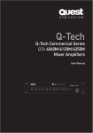
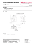
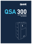
Q-Tech
Commercial Series
QTA6060M/6120M/6240M
Mixer Amplifiers
User Manual
QTA 6060M
CHANNEL 1
MIN
MAX
CHANNEL 2
MIN
MAX
CHANNEL 3
MIN
MAX
CHANNEL 4
MIN
MAX
CHANNEL 5
MIN
MAX
OUTPUT LEVEL
PUBLIC ADDRESS AMPLIFIER
BASS
MIN
Pwr -10
TREBLE
MAX
MIN
MASTER
MAX
MIN
MAX
-8
-3
0
+3
+8
POWER
WARNING
THIS APPLIANCE MUST BE EARTHED
General Installation
DO NOT run unbalanced high impedance
microphone cables near mains, data,
telephone or 70/100V line cables.
DO NOT run 70/100V line cable near data,
telephone or other low voltage cables.
DO NOT exceed 90% of the amplifiers output
power when using 70/100V line (speech only).
DO NOT exceed 70% of the amplifiers output
power when using 70/100V line (high level
background music).
IMPORTANT
The wires in the mains lead are coloured In
accordance with the following code:
Green and Yellow: Earth (E)
Blue:
Neutral (N)
Brown:
Live (L)
As the colours of the wires in the mains lead
of this apparatus may not correspond with the
coloured markings identifying the terminals in
your plug proceed as follows:
The wire which is coloured green and yellow
must be connected to the terminal which is
marked with the letter N or coloured black.
The wire which is marked with the letter L or
coloured red.
If a 13 Amp (B.S.1363) plug or any other type
of plug is used, a 5 Amp fuse must be fitted
either in the plug or at the distribution board.
DO NOT use voice paging horn loudspeakers
for background music unless the loudspeaker
has been specifically designed for this
purpose.
AVOID jointing the microphone cable,
when this is unavoidable make sure a good
screened connector is used.
ALWAYS use balanced low impedance
microphone cable terminating to balanced
inputs on long cable runs.
ALWAYS use a mains grade double insulated
cable for the loudspeaker cable runs when
run in conduit together with power cables.
ENSURE that all loudspeakers are in-phase.
ENSURE that there are no short circuits on
the loudspeaker line before connecting to the
amplifier. It is also advisable to check the final
impedance to the amplifier with a dedicated
impedance meter to determine power draw is
within the amplifiers limits.
QTA-6060M/6120M/6240M
User Manual
Contents
Introduction. . . . . . . . . . . . . . . . . . . . . . . . . . . . . . . . . . 2
Description . . . . . . . . . . . . . . . . . . . . . . . . . . . . . . . . . . 2
Front Panel Layout. . . . . . . . . . . . . . . . . . . . . . . . . . . . . 3
Rear Panel Layout. . . . . . . . . . . . . . . . . . . . . . . . . . . . . 4
Power Source . . . . . . . . . . . . . . . . . . . . . . . . . . . . . . . . 5
Main Connections. . . . . . . . . . . . . . . . . . . . . . . . . . . . . 5
Power Amp Output . . . . . . . . . . . . . . . . . . . . . . . . . . . . 6
1
Installation Practice . . . . . . . . . . . . . . . . . . . . . . . . . . . 6
Operation. . . . . . . . . . . . . . . . . . . . . . . . . . . . . . . . . . . . 7
Specifications . . . . . . . . . . . . . . . . . . . . . . . . . . . . . . . . 8
Trouble Shooting. . . . . . . . . . . . . . . . . . . . . . . . . . . . . . 9
Technical Notes. . . . . . . . . . . . . . . . . . . . . . . . . . . . . . . 9
Q-Tech Commercial Series
User Manual
QTA-6060M/6120M/6240M
User Manual
Introduction
Description
Congratulations on your purchase of a new
Q-Tech Commercial series amplifier. Quest
Engineering Q-Tech Series amplifiers are
engineered and built to a standard that will
satisfy the most demanding environments of
commercial installation audio.
The Q-Tech Range of Mixer amplifiers are of
very high quality and come supplied full of
features.
For your safety and continuing reliability of
your Quest amplifier, please read all the safety
instructions and familiarize yourself with the
amplifiers functions and installation procedure
section before installing and operating the
amplifier. Quest has paid great attention
to detail in order to maintain strict quality
assurance standards of all Q-Tech Series
amplifiers.
2
It follows that if your audio installation is
completed with the same attention to detail,
your amplifier will deliver its best results.
Please red the section: Constant Voltage
Distributed Speaker Systems Demystified.
Unpacking: Please inspect the amplifier
carefully immediately after unpacking. If
you find any damage, notify your supplier/
dealer immediately. Only the shipper may file
a damage claim with the carrier for damage
incurred during shipping. Also check that the
voltage is correct for your local power supply.
User Manual
Q-Tech Commercial Series
• In built chime tone module
• Phantom Power on all mic inputs
• Telepaging input with selectable priority
• 24v DC power inputs
• Built in Mic/Line Priority
• Low Signal to Noise ratio
• Complete with barrier strip, XLR or
¼ in jack Mic input connections
• Pre Out function
• Tape Output
• External Mixer input
• All Mic inputs selectable as Mic or Line
• The Mixer amps can also drive up
to three external power amps
QTA-6060M/6120M/6240M
User Manual
Front Panel Layout
QTA 6060M
CHANNEL 1
MIN
MAX
CHANNEL 2
MIN
MAX
CHANNEL 3
MIN
MAX
CHANNEL 4
MIN
MAX
CHANNEL 5
MIN
OUTPUT LEVEL
PUBLIC ADDRESS AMPLIFIER
BASS
MAX
MIN
Pwr -10
TREBLE
MAX
MIN
-8
MASTER
MAX
MIN
-3
0
+3
+8
POWER
MAX
1
Channel 1 Volume Control
7
Master Tone Control (Treble)
2
Channel 2 Volume Control
8
Master Volume Control
3
Channel 3 Volume Control
9
Power On / Off switch
4
Channel 4 Volume Control
10
Power On / Off indicator LED
5
Channel 5 Volume Control
11
Output Level indicator LED
6
Master Tone Control (Bass)
Q-Tech Commercial Series
3
User Manual
QTA-6060M/6120M/6240M
User Manual
230V
Rear Panel Layout
4
1
Mains Input Socket
13
MIC 4/Aux 4 Selector Switch
25
Chime Selector Switch
2
Power Fuse
14
Aux 4 Input (RCA Jack)
26
Chime Screw Terminal
3
Earth Connection Screw
15
Aux 3 Input (RCA Jack)
27
Speaker Output Terminals
4
Power Amp in
16
MIC 3/Aux 3 Selector Switch
28
DC Power Supply Terminals
5
Pre out (RCA Jack)
17
MIC 3 Input (XLR Jack)
29
MIC 5 Screw Terminal input
6
Tape Output (RCA Jack)
18
MIC 2 Input (XLR Jack)
30
MIC 4 Screw Terminal input
7
Aux 6 Level Control
19
MIC 2/Aux 2 Selector Switch
31
MIC 3 Screw Terminal input
8
Aux 6 Input (RCA Jack)
20
Aux 2 Input (RCA Jack)
32
MIC 2 Screw Terminal input
9
Aux 5 Input (RCA Jack)
21
Aux 1 Input (RCA Jack)
33
MIC 1 Screw Terminal input
10
MIC 5/Aux 5 Selector Switch
22
MIC 1/Aux 1 Selector Switch
34
Tel Page Input (Screw Terminals)
11
MIC 5 Input (XLR Jack)
23
MIC 1 Input (XLR Jack)
35
Tel Input Level Control
24
Mains Voltage (115V/240V)
Selector Switch
36
MIC 1 Mute On/Off Switch
12
User Manual
MIC 4 Input (XLR Jack)
Q-Tech Commercial Series
QTA-6060M/6120M/6240M
User Manual
Power Source
The supply transformer has been designed for
use on either 115Vac or 240Vac, selected by a
slide switch on the rear panel. The amplifier is
factory set at 240Vac mains voltage.
Battery Connection (24V DC)
When using external batteries, earth the
amplifier via the screw terminals on the rear
of the amplifier because of the high voltages
present. Electrical stability of the system
will be improved by providing a good earth
ground. NOTE: the connection cable must be
fitted with an in-line fuse. Quick blow type 5A(
60W) 8A(120W) 15A(240W). When connecting
batteries, please ensure correct polarity.
Main Connections
Microphone Inputs
Five microphone inputs are provided, the
microphone amplifiers are an electronically
balanced, transformer-less design configured
for optimum low noise performance. The input
impedance is greater than 2kΩ and is suitable
for microphones in the 200Ω to 600Ω range.
For balanced microphones, connect the cable
screen to pin 1, the in phase signal to pin 2
and the reverse phase to pin 3. To operate the
channel in the unbalanced mode, connect pin
3 to pin 1 (ground) inside the XLR cable plug.
Use pin 2 as hot and pin 1 as screen (ground),
see diagram below: Pin Assignments:
2
1
2
1
3
3
Plug
Socket
Viewed from Solder
Side of Plug/Soceket
Balanced Audio (3 pole XLR):
Pin 1:
Ground / Screen
Pin 2:
In phase / +ve / Hot
Pin 3:
Out of phase / -ve / Cold
Unbalanced Audio (3 pole XLR):
Pin 1:
Ground / Screen
Pin 2:
Signal
Pin 3:
Ground / Screen (connect to pin 1)
For best performance when using long lines
between microphones/mixer and or amplifier
use balanced lines. These have the effect of
cancelling out any noise or hum that may be
induced into the cables.
Phantom power facilities are provided;
either of the mic inputs can be configured to
operate with 15V phantom power by setting
the relevant jumper to the ON position. Care
should be taken to ensure that phantom
power is activated only when the microphone
connected to the input requires external
phantom power
In addition to the XLR microphone inputs, the
option exists for installing Microphones via
the barrier strip provided.
VOX Muting
The TEL input has voice activated (VOX
priority) muting over CH1~CH5 and AUX 6.
Priority Microphone, Mic1 input, has VOX
priority over CH 3~6 and Line input signals
but does NOT mute Channel 2 input.
5
Line (Aux/CD) Connection
The equipment provides an auxiliary input
which may be used for connecting other
signal sources such as a Radio Tuner, CD
or Cassette player. A push button switch is
located on the rear panel for selection of,
Mic1→Aux1, Mic2→→Aux2, etc.
The line level Control on the front panel
operates on each of the input sources.
To operate, select the desired music source
using the slide switch and turn the “Channel”
control clockwise to increase the volume, or
anti-clockwise to reduce the volume.
The Aux / input sockets are standard stereo
RCA phono. Single sockets are supplied
and these are linked together internally. This
allows stereo signal sources to be used
without the need to obtain a special lead,
however you may wish to check with the
manufacturer of the signal source to ensure
that no damage will result if the left and right
output channels are put in parallel.
Q-Tech Commercial Series
User Manual
QTA-6060M/6120M/6240M
User Manual
RCA Phono Plug Connections
Low Impedance 8Ω or (4Ω):
Tape Output Connection
This output allows connection of standard
low impedance loudspeakers. The minimum
impedance must be 4Ω. When two or more
loudspeakers are in use, ensure that they are
wired in such a way that the impedance load
is between 4Ω and 16Ω.
These are standard RCA stereo phono
sockets, and provide a mixed output suitable
for connection to a tape or digital recorder.
As a guide for the correct gauge of wire, we
recommend the following:
Pre Out / Aux Out
6
The horseshoe jumper “U” connects the
mixer/preamplifier stage to the power
amplifier stage. This Insert Point will allow
for connection of signal processors such
as equalisers, compressors or Feedback
Exterminators. The Insert Point is located
(electronically) between the mixer and power
amplifier sections of the amplifier. It allows
for the “mixed” output of the amplifier to be
processed externally and then returned to the
power amplifier section of the amplifier. The
connecting link must be plugged in for normal
operation as a mixer/amplifier. “PRE OUT” is
after the tone controls and the master volume
control.
Chime Output
Chime is a two tone “DING DONG”. This is
obtained by shorting screw terminals. Chime
tones mute all channels. A slide switch
located adjacent to the speaker output
terminal strip allows the enable/disable Chime
function.
Power Amp Output
Additional amplification can be achieved
by connecting the “PRE OUT (2)” output
to another power amplifier. Under normal
conditions, up to three power amplifiers can
be connected in this way.
Loudspeaker Connection
Note: Use only 100V or 70V (Selectable) Line
Loudspeakers
User Manual
Q-Tech Commercial Series
100V
70V
Up to 50m
AWG25-26
(0.15mm2)
50m - 200m
AWG20
(0.5mm2)
Over 200m
AWG18
(0.75mm2)
Up to 50m
AWG24
(0.20mm2)
50m - 200m
AWG17
(1.0mm2)
Over 200m
AWG16
(1.5mm2)
Up to 10m
AWG18
(0.75mm2)
10m - 30m
AWG13
(2.50mm2)
Low Imped. (4)
Installation Practice
Step 1. Take a piece of figure-8 cable,
connect the stripe/coloured wire to the100V
terminal and the uncoloured wire to the COM
on the amplifier terminal strip.
Step 2. Connect the other end of the wire
(uncoloured) to the Com/EARTH connection
on the ceiling speaker transformer and the
other + (strip) wire to the required voltage
taping.
Step 3. Take a second piece of figure-8 cable
and connect the plain wire to the parallel COM
connection and the other + (stripe) wire to the
parallel output from the transformer terminal
block and connect it in the same way to the
next ceiling speaker.
QTA-6060M/6120M/6240M
User Manual
Step 4. Continue this process until all the
ceiling speakers are connected in a parallel
connection with all the COM connections
and all the wattage connections following a
parallel connection.
Common problems with ceiling speaker
installations System is distorting. Check for
the following causes:
1. Too many speakers set to too high a power
tapping for the power of the amplifier.
Solution: Calculate the total power
draw and re connect the speakers
to a lower the wattage tapping. (See
“Determining power by calculating
total impedance.” on page 10)
Some cheap ceiling speakers have
incorrect taping labels. A 10 watt speaker
may really be drawing 15 or 20 watts.
The only way to test this is with an
impedance meter on a single speaker. A
15% discrepancy can mean that a 100
watt system will only be able to power 7
or 8 x10 watt speakers safely. Be aware of
this booby trap. Always plan to have 20%
more power than you think you will need.
2. Incorrect output connection: If you accidentally connect your terminal strip
on the amplifier to the 8 ohm output
instead of the 100/70V line, you will have
distortion and risk damaging the amplifier.
3. Short circuits and no circuits: Check that
your wiring has not been accidentally cut,
miss-connected or generally damaged
in the course of installation. This can be
common with building sites with multiple
trades people installing equipment into the
same ceiling cavities as the audio system.
Operation
For the best noise performance, turn the input
level control to a high setting and use the
Master as the volume control. Use the other
input level controls to set the required mixing
ratios. If you are using the auxiliary inputs,
adjust the bass and treble controls to get the
desired sound.
The Q-Tech range of amplifiers has a 7 stage
LED ramp for Signal Present/Overload (green/
red). Green indication occurs when there is
a signal present. This LED display should be
glowing green when signal is present. If this
lamp is off, the reason maybe:
A. The Input may not be connected.
B. There is little or no signal
present at the moment.
C. There is a Mic connected to a
channel switched to LINE.
D. The Mic needs Phantom Power
(See Rear Panel Layout).
7
E. The LEVEL control needs to
be increased (clockwise).
F. The cable is not wired properly
A red glowing LED indicates that the levels
are so high that distortion due to clipping is
occurring or imminent.
Check these conditions:
A. The LEVEL control may be turned too high.
B. The Output of the preceding device
may need to be reduced.
C. The Input may be switched to MIC with a
line-level source. Switch the Input to LINE.
Q-Tech Commercial Series
User Manual
QTA-6060M/6120M/6240M
User Manual
Specifications
Type
Mixer Amplifier
Model
Supply
QTA-6060M
Mains Voltage
QTA-6120M
QTA-6250M
AC 115V/ 240V, 50 / 60Hz ± 10% Switchable
Battery Voltage
DC 24V (MAX 10% deviation)
Output Power:
60W
120W
240W
Speaker outputs: 4Ω, 8Ω, 70V, 100V
Tape output: 1V 4.7KΩ
Outputs
Pre output: 1V, 600Ω
Aux Mains Power: 4A/115V
Mic 1~5: sensitivity. Adjustable (1mV), 600Ω balanced.
Aux 4~6: 150mV, stereo 22K,
Inputs
TEL: 150mV, Adjustable 600Ω, balanced
Power amplifier in: 1V
Mic 1~Mic 5: 60Hz ~ 12KHz ± 3dB
Aux 1~ 6: 50Hz ~ 15KHz ± 3dB
TEL: 50Hz ~ 15KHz ± 3dB
Frequency response
Total harmonic distortion
8
Less than 1% @ 1KHz, rated power
All Volume Controls: 80dB below rated power
Mic 1~ 5: 60dB below rated power
Tel: 80dB below rated power
Aux: 80dB below rated power
Signal to noise ratio
Bass : ± 10dB at 100Hz
Treble : ± 10dB at 10KHz
Tone Controls
Channel 1~5 volume control
Aux 6 volume control
Master volume control
Tone controls (Bass, Treble)
TEL volume control
Mute slide switch
Mic 1/Aux 1 push switch Rear Mounted
Mic 2/Aux 2 push switch Rear Mounted
Mic 3/Aux 3 push switch Rear Mounted
Mic 4/Aux 4 push switch Rear Mounted
Mic 5/Aux 5 push switch Rear Mounted
Chime Control
AC 115V / 240V voltage Selector switch
Controls
Indicators
Power indicator (LED), output level indicators (6 LEDS)
AC power consumption
150W
300W
600W
DC power consumption
5A
8A
15A
Phantom power
Factory set “on” @ 16V, defeatable via internal jumpers
TEL mutes all channels
Channel 1 can mute Channel 3 ~5, Aux 3~6
Priority
Dimensions (H x W x D) mm
Weight
Colour
Mounting options
User Manual
Q-Tech Commercial Series
88mm(H) x 426mm(W) x 13.5”D
8.5
9.5
11.5
Black
Table top or 19” rack mountable / Rack Mount Ears Included
QTA-6060M/6120M/6240M
User Manual
Trouble Shooting
Technical Notes
If the amplifier doesn’t appear to be working
normally, please check the following,
Constant Voltage Distributed
Speaker Systems Demystified
No Power, No indicator Lights working
• Make sure amplifier power switch is on.
• Make sure mains power switch is on at
the wall.
• Check the mains and DC fuse.
• Replace with only the correct type and
rating. Over rated fuses with invalidate
warranty.
Distorted Output
• Check that the speaker type is correct for
the output that you are using (ie.4-16Ω,
70V or 100V line).
• Check for any short circuits on the
speaker line.
Very Low Output Volume
• Make sure that the input is the correct
level (check for shorted connectors).
In a typical paging and background
music speaker installation, a quantity of
loudspeakers are placed across a single
amplifier in a parallel wiring configuration (see
Fig. 1.).
Each ceiling speaker will contain a small
transformer and you will notice that the
connection block near the transformer will
have a common terminal (C or earth), and a
number of wattage terminals.
Connect the wattage setting terminal for the
desired acoustic output (volume) level you
need from each individual speaker.
This will be a 100V setting in Europe and
most of Asia and 70V in the USA. (See the
explanation below)
100V Line Public Address System
9
• Check for any short circuits on the
speaker line.
• Check if signal LED on the front panel is lit
to indicate there is signal.
• If it is not lit there is no signal present.
Continually Blows Fuses
• Make sure that the speaker line is not
shorted.
• Check speaker types, ratings and if on
correct output.
Amplifier Keeps on Cutting In & Out
• Make sure that there is adequate
ventilation around the amplifier.
• Check the vent slots on the front, top and
sides are not covered or blocked and the
fan on the rear is functioning correctly.
• Check also speaker types, ratings and for
any short circuits on the speaker line.
No Output Volume
• Check the Send/Return link is in place.
Fig. 1
Remote Speaker
with 100V Line
Transformers
Often some speakers need to be set at
different volume output levels, and the
calculations involved in determining the actual
load impedance at the amplifier’s output
can be quite involved but there is a simple
technique for not overloading the amplifier.
As for the amplifiers, there are two common
standards, 100 Volt line in Europe and Asia
and 70 Volt line on the American continent.
For the purpose of simple calculations, we will
use the European standard for this exercise.
On the rear of a 70/100V amplifier you will find
an output terminal strip. This terminal strip
will contain a number of + voltage outputs
(70V 100V) and a terminal at one end for the
negative return wire (COM).
Q-Tech Commercial Series
User Manual
QTA-6060M/6120M/6240M
User Manual
A low impedance terminal will be for
8-ohm speaker installations and is under
no circumstances to be connected to a
transformer type speaker system.
How to calculate the correct
number of speakers and what
wattage connection for a given
amplifier power.
If you connect too many speakers to an
amplifier you will have distortion, overheating
of the amplifier and generally poor
performance. The problem is not really “too
many speakers”, it is more a problem of “too
much wattage draw exceeding the output
capability of an amplifier. A similar problem
would be trying to draw 2,000 watts from
a 1,000 watt generator. Sooner or later….
Expect a system failure.
10
Let us take a 100 watt amplifier. If you have
20 speakers and you set them at the 5 watt
taping, you will have a total 100 watt draw
which is the maximum output of the amplifier.
This is correct in theory but in practice you
will be safer connecting 18 speakers, not 20.
The reason is that most ceiling speakers draw
more than their claimed wattage.
The alternative would be to connect the
speakers to the 4 watt transformer terminal
giving you a theoretical total draw of 80 watts
and thus, plenty of “headroom”. One watt
difference is not very noticeable as far as
output sound pressure level in concerned.
A system that does not distort will give
much clearer voice reproduction than a
louder system that is distorting or loosing
the sibilant frequencies.
There is a formula for testing the potential
power of the system by measuring the
impedance of each speaker and then adding
all the figures to a total impedance, which is
then compared to the amplifier’s expected
impedance/power figures.
User Manual
Q-Tech Commercial Series
The quick way is to just add up all the
wattages and then give yourself 10-20%
headroom by reducing the number of
speakers per amplifier or lowering the
wattages slightly.
For the benefit of those who want to calculate
the power of the system with a formula. See
below:
Determining power by calculating
total impedance.
The alternative to counting the speaker taping
watts is to calculate the total impedance of
the line, which will also indicate the wattage
necessary to drive the system correctly.
The computational formula is voltage squared
divided by impedance:
Power = Voltage2 / Impedance.
When the speaker line reaches its top voltage
of 70 Volts, the formula is:
Power = 5000 / Impedance (because 70
squared equals 5000).
To measure impedance a dedicated meter is
required. These use a 1k frequency to send an
alternating current through the transformer(s).
The resulting figure indicated by the meter’s
dial can be cross referenced with the meter’s
impedance chart to see what value should be
expected and the power that will be required.
QTA-6060M/6120M/6240M
User Manual
High impedance of speakers and output calculation table for 100Volt systems
Output
Impedance
Output
Impedance
Output
0.1W
100KΩ
10W
1KΩ
40W
Impedance
250Ω
0.5W
20KΩ
15W
667Ω
50W
200Ω
133Ω
1W
10KΩ
20W
500Ω
75W
2W
5KΩ
25W
400Ω
100W
100Ω
3W
3.33KΩ
30W
333Ω
150W
66.7Ω
5W
2KΩ
35W
286Ω
200W
50Ω
(100V plan) P = E x E / Z = 100x100 / Z = 10,000 / Z
P: Power(W), Z : Impedance (Ω), E : 100V(Designed voltage of a general-use amplifier)
11
Q-Tech Commercial Series
User Manual
QTA-6060M/6120M/6240M
User Manual
12
User Manual
Q-Tech Commercial Series
www.questaudio.net
Quest Engineering Pty Ltd
86 Derby St. Pascoe Vale VIC 3055
Ph 613 9354 9133 | Fax 613 9354 9233