1
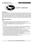
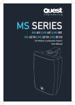
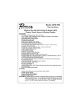
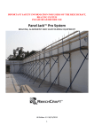
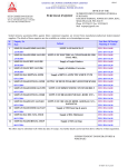
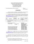
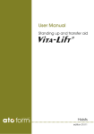
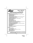
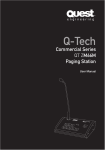
QSA 200i
ACTIVE LOUDSPEAKER
user manual
QSA200i
User Manual
QSA200i
User Manual
2
Safety Precautions
Safety
03
Installation
04
Connections
05
Glossary
06
Operating Tips
07
Troubleshooting
08
Inputs and Outputs
09
Specifications
10
Accessories
11
Flying and installation of this
speaker cabinet must be carried out
by suitably qualified personnel
following the approved safety
standards.
Do not expose the speaker cabinet
to direct precipitation or stand in
water. Liquid getting into the box
will risk a short circuit and will be
hazardous.
Do not attempt to clean any plastic
parts with solvents or petrochemical
based cleaners.
Do not stack the speaker cabinet
in a manner that could cause injury
should a cabinet become dislodged.
The power voltages inside this
device are high and could cause
serious injury or death if touched
while the power is connected. Do
not open the amplifier case as there
are no user serviceable parts inside.
Do not place sources of heat on the
speaker cabinet such as lighting
equipment or smoke machines.
Very important
Before connecting or operating your new
Quest Engineering speaker, please study the
accompanying instruction manual paying particular
attention to the operating precautions and wiring
procedure.
Before using your speaker check to make sure
that the selection of the power supply voltage
(115/230 Volts) is set correctly for your country. An
incorrect setting can lead to severe damage to your
new powered speaker on activation. If you are not
certain that it is set correctly, check with your Quest
Engineering dealer.
Register Your Product
Thank you for choosing Quest. Please take the time
to complete your procuct registration card which is
included with the packaging. Registering your Quest
Engineering product will:
User Manual
QSA200i
Active Loudspeaker
3
Attention
Quest Engineering will not assume responsibility for
incorrect installation or operation of this product.
SAFETY
CONTENTS
Contents
• CONFIRM YOUR WARRANTY
• REGISTER YOUR PRODUCT
• PROTECT YOUR NEW PRODUCT
QSA200i
Active Loudspeaker
User Manual
4
QSA200i
User Manual
Description
Safe installation procedures
The QSA speaker range is a two-way active bass
reflex design suitable for mobile or installation
use. The power amplifiers are multiple integrated
A-B class design capable of high power yet light
in weight. There are separate amplifiers for the
high and low frequency drivers and both are
protected by an “analogue engine” processor
that monitors peak and RMS power and makes
EQ and time alignment corrections.
• The QSA200i should be installed using the
WBFS bracket and secured by both top and
bottom nut inserts.
The operation of these devices will not affect
audio quality due to their advanced design.
Audio processors will control and protect the
system to a reasonable degree but are not a
substitute for sensible operation. The system will
sound at its best when mixers and other signal
processors in the audio chain are not being over
driven into distortion.
• The QSA200i can be hung with “I” bolts
attached to the top 8mm insert bolts.
Quest QSA200i Series: Rear Panel Description
1
2
• Under no circumstances attach the box with less
than two of the threaded inserts (see figure a)
3
• The speaker box must not be installed in a manner
where the weight is not equally distributed between
two insert points.
4
• One pair of threaded inserts may only carry
the weight of one box. Therefore multiple box
rigging from one pair of insert points should not be
attempted. (see figure b)
5
6
• Do not locate boxes near sources of moisture or
where water can enter the box. (see figure c)
Full range or
mid-high applications
The design characteristics make the QSA series
suitable for both full-range use or as the high-mid
component of a multi-way system with sub-bass
enhancement. Coupled with a Quest Engineering
sub-bass system, the QSA200i will provide very
good full bandwidth audio coverage at medium
to high sound pressure levels.
7
(b)
9
10
11
(c)
Flying installation
1. Power amp active indicator.
Two M6 thread inserts are located on the top and
one under the QSA series enclosures. These are
intended to be used with the designated wall
mount bracket.
2. Clip/limit indicator. If this LED illuminates for
more than an occasional flash, turn down the
mixer output. If you need more volume, set up
more speaker boxes.
QSA Series flying accessories
3. Microphone balanced input volume control.
See page 11 for list of accessories.
4. Line level volume control.
5. Microphone level (low impedance) input.
6. Line level balanced input.
(To mixer or other +4 dB or less line level)
User Manual
QSA200i
Active Loudspeaker
5
8
(a)
Installation
Temporary installation is possible with the 35mm
stand mounting in the base of the enclosure.
Fold-back installation is possible with the
addition of the floor stand/wall bracket optional
accessory, (WBFS8).
CONNECTION
INSTALLATION
QSA200i
User Manual
7. Line out. This is a through output of the
same level as the line input.
8. Loop/Mix Output mix selector signal in/out
through
9. Power on/off switch.
10. Power supply input. Make sure that the
voltage selector is set for your Country’s
correct voltage.
11. Protection fuse. Use only fuses of the correct
Amp rating. If it blows more than once, return
the box to a Quest Engineering service centre.
QSA200i
Active Loudspeaker
User Manual
QSA200i
User Manual
Operating Tips
Basic professional audio practice and hints for best results
To avoid overloading the pre-amp inputs, always
operate the master volume at a high level and
control the volume from the input volume.
POWER AMPLIFIER: Boosts the signal enough
so it can be reproduced by a loudspeaker.
ELECTRONIC CROSS OVER: Splits up the
full range audio signal to separate high and low
frequencies. This is done to send low frequencies
to the bass speaker and high frequencies to the
tweeter or high frequency horn driver.
6
Hi Freq.
Amp
Electronic
xover
Hi Freq.
Drive
Input
Signal
10
Compressor
Threshold
CLIPPING: Distortion that is caused by having too
much signal at an input causing the amplifier to
overload. It is called clipping because it will cause
a smooth wave to be cut off at the peak of the
wave. In other words, “clipped”
Clipping
Clipping
GAIN STRUCTURE: The relationship of input
levels to output levels in a signal chain. An
example of incorrect gain structure is when a
mixer is turned up to the point of audible distortion
(red lights flashing serious overload), and the
power amplifiers are turned down and running at
only 30% power.
QSA200i
Active Loudspeaker
Do not run the system with the mixer “peaking
in the red” while the box is turned down.
AMP
10
10
5
5
1
1
5
0
1
10
CLIP/LIMIT
2
MIXER
AMP
10
10
5
5
1
1
5
10
LIMITER: An electronic device that will prevent
the signal from exceeding a set level of output.
Normally used as a system protection to prevent it
from being over driven by excessive input.
Red lights flashing on a mixer indicate distortion.
If you have a mixer with the facility to show you
the input level on a meter, for example then you
push a CUE/PFL button, set the input level to
below the level of the red end of the LED ramp.
0
1
0:1
1:1
10
PHASE (IN or OUT OF PHASE): This really means
speaker polarity. The input terminals of a normal
loudspeaker have a + positive red terminal and a
- negative black terminal. In the case where there
are two speakers operating as a pair or together
as an array, will need to all be wired the same way.
If a speaker connecter, speaker lead or speaker
box is wired in reverse to a box near it, loss of
performance will result. This may be in the form
of lost low frequency response. In this case you
will see the bass speaker working hard but as you
move away from the box, the bass frequencies will
seem to “disappear”.
If you run the row of red lights to the end of the
ramp you will cause distortion at the very start
of the pre amplifier stage of the mixer. At this
point it will sound dirty and “fizzy” regardless of
how good the rest of your sound system is. The
rest of the system will be reproducing a distorted
sound. If you need more volume, turn down the
input signal so it is out of the red and turn up the
output of the mixer.
10
MIXER
AMP
10
10
5
5
1
1
5
0
1
7
CLIP/LIMIT
2
10
Limiter
Threshold
SELF-POWERED: Refers to a speaker or a mixer
that contains a power amplifier.
The ideal situation is to have all the components
of the audio chain operating at the same
operational range.
Also do not operate the system with the input
peaking (red overload light on or flashing) and the
master volume turned down.
3:1
1:1
Low Freq.
Drive
Low Freq.
Amp
User Manual
COMPRESSION: An electronic device that
reduces the dynamic range. In other words,
makes the loud parts of the music less loud and
the quiet parts appear louder. When used correctly
it can make live music sound more even and
balanced.
Output Level
PRE-AMPLIFIER: That part of the signal chain
where a signal from a microphone, turntable, CD
player or other signal source is first amplified.
This will normally be at the input of a mixer and is
necessary to boost the signal enough to be then
mixed and amplified by a power amplifier.
MIXER
OPERATING TIPS
Glossary
Output Level
GLOSSARY
QSA200i
User Manual
10
CLIP/LIMIT
2
Check that your speaker leads do not have one
lead wired in reverse at one end and that the
speaker boxes are all wired correctly internally.
This can happen when a speaker box has been
repaired and then not assembled with the wiring
connected correctly.
QSA200i
Active Loudspeaker
User Manual
8
QSA200i
User Manual
Troubleshooting
Inputs and outputs
Buzzes and noises in the sound system
The inputs can accept both XLR and phono
connectors. If you are connecting multiple boxes
together is unprofessional practice to use a
mixture of both phono and XLR types of leads.
Use one or the other otherwise an out of phase
situation can result.
Getting rid of unwanted noises is a study in
itself. Most of the noise, (apart from undesirable
program) will fall into three categories.
(1) WHITE NOISE: This is the hiss that suggests
that the gain structure is set incorrectly.
Something in the signal chain is boosting too
much or an input is set too sensitive. If your
equipment has gain switches on it, set them all
the same. If the switch is labelled +4dB, set them
all to that figure. If one piece of equipment seems
to be overloading, set them all to -10/-20dB and
be prepared to boost the input level of the QSA
input. The last unit in the chain should be set
to +4 dB at the output stage if possible when
connected to the line level input of the QSA
series input.
(2) LOW FREQUENCY HUM: This is often
caused by noise from the power leads being
picked up by the audio signal cables. The
preferred solution is to connect up your system
with “balanced” XLR microphone cables.
Especially if you are running the cables a long
distance, (more than 5Mtrs /15 Ft). The other
solution is to make sure that your audio cables
are as far from power cables as possible.
(3) BUZZ: Sometimes you can experience a hum
and buzz together. A buzz is almost always a
problem with the “earthing” of the system. It will
often occur when you have the system powered
from sperate power outlets in the same building
or audio and lighting sharing a common power
circuit.
Tips on “flying clusters”
When very high output or broad coverage is
required, it is common practice to assemble an
array of speakers together.
In a flown horizontal array of high/mid configured
speakers, best results are obtained by angling
the boxes apart slightly at the front of the array
while the rear of the boxes must be together on
the same vertical plane.
The purpose is to minimise phase shift and
interference effects between the boxes. If two
boxes are directing acoustic energy into the
same coverage area, loss of smooth frequency
response will result. This is called “lobing” as
“fingers” of both frequency peaks and dips
spread out across the coverage area, especially
at the area where the signal from the overlapping
coverage converges.
Even when the audio and lighting systems are
powered from separate sources, there can still
be a common earth between them. For example,
a smoke machine may be powered from the
lighting system, yet the trigger mechanism could
be connected to the audio system through the
audio multi-core/snake.
An earth connection between the audio and
lighting will now exist and a buzz could be
amplified in the audio system. The simple
solution is to power your audio circuit and
everything connected to it from the same source.
If the buzz persists, check your signal cables,
one may have an earth/shield disconnected.
INPUTS/OUTPUTS
TROUBLESHOOTING
QSA200i
User Manual
9
QSA 200i Array
A cheap but possibly life saving investment is a
domestic power tester to check that the power
supply sockets are correctly wired. Faulty or
incorrectly wired power is a booby trap that is
more common than you think.
It is wise to avoid switching on or off devices
in the signal path while the speaker system is
powered and turned up. Otherwise loud clicks
and bangs could result. When shutting down the
system, always turn the speakers off first. This
is to prevent the speaker amplifying the sound
of the other equipment in the chain being shut
down. The reverse is true when powering up.
Mixers and effects on first, power amplifiers or
powered speakers on last.
User Manual
QSA200i
Active Loudspeaker
QSA200i
Active Loudspeaker
User Manual
QSA200i
User Manual
QSA200i
User Manual
10
Accessories Essentials for your QSA
Frequency Range -3dB
70 - 20 kHz
QB350
Protective nylon speak bag
HF Coverage Angle
90˚ x 45˚ Revolving horn flare
QSSAL
Heavy duty aluminium speaker stand with carry bag
Max SPL
123 dB (C weighted)
WBU8I
U wall bracket to suit QSA200i & QS/150
Amplifier Power
HF 50 Watts LF 100 Watts
WBFJ8
Wall bracket / foldback adaptor
Transducer
1x ¾-inch Compression driver
1x 8-inch Long coil bass driver
Enclosure
Injection molded plastic
Protective Grill
Perforated steel acoustic foam covering
Input Connections
2 channels XLR in XLR through out
Dimensions
250mm (10") x 240mm (9.5") x 430mm (17")
Net Weight
8 kg
Installation Options
365mm pole mount
WBFS-8 wall bracket/floor stand
WBU8i wall bracket through 6mm insert bolts
ACCESSORIES
SPECIFICATIONS
Quest QSA 200i: Specifications
11
QB350 & QSSAL
WBFJ8
WBU8I
WBFJ8 with QSA200i attached
Product features
· Two-channel independent XLR mic/line inputs
· XLR line our with mix add function
· Long lasting heavy-duty Quest speaker
components
· Uniform high frequency coverage with custom
designed rotating HF wave-guide
· Great sonic performance through analogue
engine signal processing
· Micro fan cooled multi way power amplifiers
· Steel protective full front grill
* All specifications are correct at time of printing, Quest Engineering reserves the right to change specifications at any time and
won’t be held responsible for any typographic errors in this publication.
User Manual
QSA200i
Active Loudspeaker
QSA200i
Active Loudspeaker
User Manual
www.questaudio.net