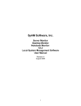
1
System Client V4.55 User Manual August 2014 1 © 2014 SyAM Software, Inc. All rights reserved. SyAM Software and the SyAM Software logo are trademarks of SyAM Software, Inc. All other trademarks are the property of their respective owners. Information contained in this document is assumed to be accurate at the time of publishing. SyAM Software reserves the right to make changes to the information contained in this document at any time without notice. For additional information, sales, or technical support, contact SyAM Software www.syamsoftware.com Table of Contents Introduction ............................................................................................................................................................... 5 SyAM Software Modules ...................................................................................................................................... 6 Compatibility ........................................................................................................................................................ 6 Deployment Options............................................................................................................................................. 7 Chapter 1: Installation and Configuration .................................................................................................................. 9 Installation Instructions – Windows .................................................................................................................... 10 Installation Instructions – Linux .......................................................................................................................... 10 Firewall Security ............................................................................................................................................ 10 Uninstalling SyAM System Client (Windows) ..................................................................................................... 11 Uninstalling SyAM System Client (Linux) ........................................................................................................... 11 Chapter 2: Logging In ............................................................................................................................................. 12 Browsing to the SyAM Web Server .................................................................................................................... 13 Ending the Session ............................................................................................................................................ 14 Chapter 3: The SyAM User Interface ...................................................................................................................... 15 The SyAM User Interface ................................................................................................................................... 16 Interface Layout............................................................................................................................................. 16 Header Bar .................................................................................................................................................... 16 Health Colors ..................................................................................................................................................... 17 Icons .................................................................................................................................................................. 18 Management Tree .............................................................................................................................................. 19 Tree Icons ..................................................................................................................................................... 19 System Detail Tab ......................................................................................................................................... 20 Monitoring Memory Errors ............................................................................................................................. 21 Power Management Tab ............................................................................................................................... 22 Hardware Detail Tab ...................................................................................................................................... 25 Network Detail Tab ........................................................................................................................................ 25 Storage Detail Tab ......................................................................................................................................... 26 SMART Drive Pre-Failure Monitoring ............................................................................................................ 26 RAID Management............................................................................................................................................. 27 RAID Controller Details Screen ..................................................................................................................... 28 Steps in Creating a RAID Set ........................................................................................................................ 29 Adding/Removing a Global Spare ................................................................................................................. 30 Deleting a RAID Set ...................................................................................................................................... 31 Software Details Tab...................................................................................................................................... 32 Installed Applications and Drivers.................................................................................................................. 32 Processes and Services ................................................................................................................................ 32 Retrieving Windows Events ........................................................................................................................... 37 Chapter 4: Configuring System Alerts ..................................................................................................................... 40 System Alert Matrix ............................................................................................................................................ 41 Monitored Sensor Types .................................................................................................................................... 42 Logical Sensors ............................................................................................................................................. 43 Notification Settings – Configuring email alerting .......................................................................................... 44 Removing a Sensor Instance From the System Alert Matrix ......................................................................... 45 SyAM Alerting Enhancements ........................................................................................................................... 46 Local Alerting ..................................................................................................................................................... 46 Integration into Enterprise Frameworks ............................................................................................................. 47 System Area Management (SyAM) MIB ........................................................................................................ 47 System Area Management (SyAM) Integration into Microsoft System Center Operations Manager 2007/2012 (SCOM) ........................................................................................................................ 47 Chapter 5: Contact Details & Glossary ................................................................................................................... 48 Contact Details ................................................................................................................................................... 49 Glossary ............................................................................................................................................................. 49 Chapter 6: System Area Manager Software ............................................................................................................ 52 Differences between System Client and SyAM System Area Manager ............................................................. 53 3 Table of Figures Figure 1: Individual systems being managed via the SyAM Local Interface ...................... 7 Figure 2: Multiple systems being managed by System Area Manager ............................... 8 Figure 3: SyAM System Client Login Screen .................................................................... 13 Figure 4: Successful Logout ............................................................................................. 14 Figure 5: System Client User Interface Layout ................................................................. 16 Figure 6: Header Bar ......................................................................................................... 16 Figure 7: Tree Expanded to Display Monitored Sections .................................................. 19 Figure 8: System Detail Tab .............................................................................................. 20 Figure 9: Power Management Tab .................................................................................... 22 Figure 10: Hardware Detail Tab ........................................................................................ 25 Figure 11: Network Detail Tab ........................................................................................... 25 Figure 12: Storage Detail Tab............................................................................................ 26 Figure 13: Storage Details – Managed RAID Controllers ................................................. 27 Figure 14: RAID Controller Details Screen ....................................................................... 28 Figure 15: Physical Drives – Choosing drives for the Array.............................................. 29 Figure 16: Available Array - Configuring the RAID Set ..................................................... 29 Figure 17: RAID Set Details – Information on Configured RAID Set ................................ 30 Figure 18: Removing a Hot Spare drive ............................................................................ 30 Figure 19: RAID Set Details – Deleting a RAID set .......................................................... 31 Figure 20: Installed Applications and Drivers .................................................................... 32 Figure 21: Processes and Services .................................................................................. 33 Figure 22: End the Process .............................................................................................. 33 Figure 23: Confirm to End the Process ............................................................................. 34 Figure 24: Starting a Service ............................................................................................. 34 Figure 25: Confirm to Start the Service ............................................................................. 34 Figure 26: Stopping a Service ........................................................................................... 35 Figure 27: Confirm to Stop the Service ............................................................................. 35 Figure 28: Create Process Alert ........................................................................................ 36 Figure 29: Create Service Alert ......................................................................................... 37 Figure 30: Retrieving Windows Events ............................................................................. 38 Figure 31: Creating an Event Log Alert ............................................................................. 38 Figure 32: Configurable Windows Event Log Alerts ......................................................... 39 Figure 33: System Alert Matrix .......................................................................................... 41 Figure 34: Entering Notification Information...................................................................... 44 Figure 35: Local Alert popup ............................................................................................. 46 Introduction SyAM Software provides a comprehensive, simple to use set of system management products for servers, desktops, notebooks and tablets. Each product has features specific to their relevant system's capabilities and functions, as well as a large number of common features. Their user interfaces are identical. The products enable several IT benefits. Among them are predictive alerting to pending failures, system configuration, unattended monitoring and alerting, remote management, and reporting. The products dynamically discover the hardware and software operating environment, and manage all physical environmental sensors available and operating system resources. Users can view them and be alerted if they exceed their thresholds. There are two levels of system management. System Client software provides a single system view. System Area Manager provides a unified view of all of your systems, and also provides more comprehensive features. The System Client management products are: Server System Client Desktop System Client Notebook System Client Tablet System Client The Central Management product is: System Area Manager This user manual describes the System Client software. The following sections will describe the product functionality of the System Client, and highlight areas of additional functionality available through the System Area Manager. 5 SyAM Software Modules System Client software contains four products: Server System Client - Used for server platforms running server operating systems and RAID storage. Desktop System Client - Used for desktop/workstation platforms. Notebook and Tablet System Clients - Used for notebook or tablet computers that are on and off the network and may have hardware or software changes made while offsite. These products can be installed on any Intel architecture x86/x64 platform running one of the supported operating systems. Compatibility Operating System Server System Client Desktop System Client Notebook System Client Tablet System Client ■ Windows 2012 Server ■ Windows 2008R2 Server ■ Windows 2008 Server ■ Windows 2003 Server ■ Windows 8 ■ ■ ■ Windows 7 Enterprise / Professional ■ ■ ■ Windows XP Professional ■ ■ ■ Red Hat Enterprise Server 4, 5 ■ Red Hat Workstation ■ ■ ■ SuSE Enterprise Server ■ SuSE Professional ■ ■ ■ Fedora Core ■ ■ ■ Linux x64 Operating System Requirements If you are running Red Hat or Fedora Core x64 Linux distribution, you must load the Compatibility Arch Support (Multi lib Support Packages). To check if this is loaded look in System Settings - Add/Remove Applications and scroll to the bottom to verify that this package is installed. If not, please install it. System Requirements 160MB Disk space 256MB Memory Browser Requirements Internet Explorer 7, 8, 9 Mozilla Firefox Deployment Options During installation you are presented two options of deployment; Local – This installs the SyAM web server and management agent, which enables you to manage the system directly via a web browser. You may also manage the system via the system running the System Area Manager software. Agent – This does not install the SyAM web server; it installs the management agent only. In this case the system is only going to be managed via the system running the System Area Manager software. Figure 1: Individual systems being managed via the SyAM Local Interface 7 Figure 2: Multiple systems being managed by System Area Manager Chapter 1: Installation and Configuration This chapter provides step-by-step installation and configuration instructions for System Client software on Windows and Linux Operating System Platforms. It is recommended that you print off the quick start guide before installing the software. This simple document will step you through installation and email configuration in a few minutes. 9 Installation Instructions – Windows 1. Load the SyAM Software CD and from the menu choose the product version you wish to install, or double click the downloaded SyAM executable. Then just follow the Install Wizard instructions. 2. Choose the language of the user interface. 3. Choose the destination folder. This cannot contain any spaces in the name. 4. Choose either the Local or Agent installation. (default=Local) 5. To enable security through 128-bit data encryption from SyAM Server Web Server to the browser, choose the SSL option. (default=No) 6. After the installation has finished, the SyAM services will start and dynamically discover and configure your system's monitoring environment. Installation Instructions – Linux 1. Download the required product version or copy it from the SyAM Software CD to the Linux system. 2. Extract the files and change permission to execute the files 3. Enter ./install – then follow the on screen instructions 4. Choose the language of the user interface. 5. Choose the destination folder (This cannot contain any spaces in the name) 6. Choose either the Local or Agent installation. (default=Local) 7. To enable security through 128-bit data encryption from SyAM Server Web Server to the browser, choose the SSL option. (default=No) 8. After the installation has finished, the SyAM services will start and dynamically discover and configure your system's monitoring environment. Firewall Security The following ports must be opened if you are using a firewall on your Linux system. They are automatically opened on Windows systems. 3894 – Used for agent management service 3930 – Used for web server if installed 5800 – Used for Remote Console access from System Area Manager 5900 – Used for Remote Console access from System Area Manager Uninstalling SyAM System Client (Windows) To remove System Client from the Windows system: 1. On the start menu, select Settings - Control Panel - Add/Remove Programs or Programs and Features. 2. Highlight SyAM System Client and select Uninstall. You will be prompted to confirm this action. 3. Following removal, if SyAM System Client is to be reinstalled, a system restart is required. Uninstalling SyAM System Client (Linux) To remove the SyAM software from the Linux system: 1. Go to the top-level directory where the SyAM software was installed. 2. ./uninstall The software will be uninstalled. 11 Chapter 2: Logging In This chapter provides details on logging into the SyAM User Interface. Browsing to the SyAM Web Server Open a supported web browser with access to a system where SyAM System Client is installed with local web interface. In the URL bar, enter: http://IPADDRESS:3930 or http://MACHINENAME:3930 Example http://192.168.1.19:3930 Example http://FILESEVER1:3930/ If you enabled SSL during installation, you are required to type “https” instead of “http”: Example: https://IPADDRESS:3930 or https://MACHINENAME:3930 This will bring you to the login screen. Figure 3: SyAM System Client Login Screen 13 The SyAM web server does not maintain its own separate set of users and passwords. It requests the operating system to log you in, so uses the accounts that are already in place on your system. To login you must satisfy the following conditions: For Standalone systems (not in a Windows Domain) The User name and Password must be valid on the system you are logging into. The User must have Administrator rights on the system. For systems within a Windows Domain The User name and Password must be valid in the Domain. The User must have "Domain Admin" rights within the Windows Domain A Valid Domain Name for the system must be entered in the Domain field. For Linux systems The Username and Password must be valid on the system you are logging into. Ending the Session When you have completed your management session, choose the Log Out button on the main header bar. Successful logout returns you to the login screen. Figure 4: Successful Logout For added security you will be logged out automatically after 30 minutes of inactivity. A message box will appear on screen if you are using Internet Explorer to let you know that you need to log back in. If you are using a Firefox browser you will be logged out and returned to the login screen. Chapter 3: The SyAM User Interface This chapter describes how to use the System Client software. It also points out some advanced features that are available in the System Area Manager products. 15 The SyAM User Interface System Client software provides administrators with the ability to view the system's current configuration and the status of the monitored sensors and resources. Additionally, the administrator can configure email notification settings. Interface Layout The structure of the interfaces is common whether you are viewing a Server/Desktop/Notebook System Client. The system being monitored is represented in the tree on the left hand side and the detailed information being accessed in presented on the main right hand side. Because System Client management software provides a single system view, there is only a single system in the tree. System Area Manager software displays many systems in the tree. Figure 5: System Client User Interface Layout Header Bar The header bar has function buttons for Refresh and Log Out, and a question-mark icon for Online Help. Figure 6: Header Bar Health Colors In order to quickly identify and correct system problems, SyAM System Client uses a consistent color scheme to represent the health and functionality of systems and their components. These colors can be seen in every level of monitoring, from the instance of the component to the component category and section. The health of each monitored system is updated on a regular interval. Any change in the status of the system will cause a change in the health color. The health color will remain in the changed state until the issue is resolved. Green = Fully Functional Amber = Warning Red = Critical Grey = System state pending, currently unknown Purple = System is no longer responding Blue = Agent service has been manually shutdown Black = System has been shut down Brown = System power state has been suspended 17 Icons There are four icons that represent the type of SyAM software running on the managed system. Server System Client/System Area Manager Desktop System Client/System Area Manager Notebook System Client Tablet System Client Management Tree Figure 7: Tree Expanded to Display Monitored Sections Tree Icons System Alert Matrix – Provides access to the thresholds, sample and reset periods, and notification options for all of the monitored hardware and software sensors within the system System – Provides system board, memory, CPU, slot, display, port information and status of the CPU and Memory utilization being monitored, in addition memory error information is displayed. Hardware – Provides sensor information and current status on physical sensors being monitored within the system Network – Provides network adapter configuration information and performance for all configured adapters within the system Storage – Provides physical storage device, storage controller, logical device information and health status for the storage devices and managed RAID controllers. Software – Provides information on OS services, processes, and installed applications. Also provides remote and process management. 19 System Detail Tab The System Tab displays detailed information on the system’s configuration, including BIOS, vendor information, operating system, location, machine name, function, memory and CPU utilization, etc. Administrators can choose to enter additional system information by filling in the fields at the top of the screen. The system's power management policies can be viewed and re-configured remotely by clicking on the Power Management button. Figure 8: System Detail Tab Monitoring Memory Errors SyAM System Client provides real time monitoring and alerting of single- and multi-bit memory errors on systems with supported ECC Memory error monitoring. The default alerting thresholds are to notify the administrator immediately on a multi-bit error or when two single-bit errors occur within a day. Through the System Area Manager the administrator can adjust the thresholds and polling interval periods for both single- and multi-bit errors, and configure their notification methods. 21 Power Management Tab (This feature is only available through the System Area Manager) On the Power Management tab, the user can display and reconfigure power management policies for the managed system. Figure 9: Power Management Tab Power Plan Name The Power Plan Name for a newly installed SyAM Windows System Client is the name of the active Windows Power Scheme. Setting up a new power plan in System Area Manager, or in SyAM Management Utilities, will create a new Windows Power Scheme and make it the active power plan. Timeout Settings From here you can configure the power scheme settings for the managed system. If the managed system is a notebook or tablet there will be two separate sets of settings: one set that will be applied when connected to AC power, and the other set for when running on battery. The options are; Turn off monitor Turn off hard disks System standby Hibernate – This will only be displayed if the system has hibernation enabled Battery This information is only displayed if the managed system is a notebook. Current Power Source – States if the system is plugged in using AC Power Cord or is running from the battery Battery Charging – States if the battery is in a charging state Battery Level – Current health state of the battery Battery Charge – The percentage of battery life available Scheduler Settings You can configure the managed system to be scheduled to perform a graceful system shutdown or restart at any time for each of the days. To enable, click on the appropriate radio button for the action to be taken that day. (No Action / Shutdown / Restart). Then set the time using the drop down box. Different actions can be set at different times for each of the days of the week. Only one action per day can be scheduled. Press the Apply Button to save the changes made. Defined Applications not to shut down if running You can enter the name of an application if found to be running it will not perform the scheduled shutdown. To add an application, enter the name of the application executable and press the Add Application button. To remove an application, click on the radio button next to the application you wish to remove and press the Remove Application button. Check for Keyboard/Mouse Activity This is the time period that is checked before attempting to perform a scheduled shutdown. Shutdown Countdown Timer This is the time period that the user is presented to cancel the scheduled shutdown. Wait Period before Rechecking This is the time period that the agent will wait before attempting to perform the scheduled shutdown. 23 Number of Attempts to Shutdown This is the number of attempts the agent will attempt to perform the scheduled shutdown for that day. System Security – User Log Off/Lock Screen Settings This feature is used to secure a system against unauthorized access when the user is not present. Use the drop down menu to enable the feature and select the inactivity timeout period. Then choose either to force a logoff of the currently logged-in user, or lock the screen, requiring the user to re-enter a password. Power Consumption Information on system power consumption is displayed here for the prior day, week and month. Number of Hours On – total number of hours system is powered on Number of Hours Suspended – total hours in suspended power state Number of Hours Powered Off – total number of hours system is powered off % Powered Off By Client – percentage of system shutdowns performed by the System Client % Powered Off By User – percentage of system shutdowns performed by the user System Uptime How long the system has been running, as reported by the operating system. Hardware Detail Tab All environmental sensors discovered on your platform are displayed in the Hardware Tab. This includes fans, temperatures, voltages, power redundancy loss and physical security. The number and type of sensors displayed is dependent upon the system platform and its configuration. Figure 10: Hardware Detail Tab Reset Chassis Intrusion Some hardware platforms that support a chassis intrusion sensor, do not automatically reset the sensor state to normal when the chassis in closed. For such systems the Reset Chassis button causes the platform to reset the state of the sensor to normal. Network Detail Tab The Network Tab displays detailed information on adapters connecting the managed system to the network, including adapter and connection speed, connection status, IP address, and MAC address. Additionally the send and receive byte counts and calculated utilization over the last approximately 60 seconds is provided. Figure 11: Network Detail Tab 25 Storage Detail Tab The Storage Tab displays detailed information on physical and logical disks associated with the system being monitored. Physical disk attributes reported include vendor information, device ID, SCSI ID, and size. Logical disk attributes reported include name, size, space allocation, and utilization. Figure 12: Storage Detail Tab SMART Drive Pre-Failure Monitoring Directly attached disk drives that are SMART capable are checked daily. Supported disk technologies include P-ATA, S-ATA, SCSI and FC. The administrator can be notified of bad disk drives before they fail and potentially lose data. Notification of a bad SMART status (Pending failure) is done via the notification options configured for the drive. The Storage Details tab visually shows physical drive status. A physical drive in the warning state (amber colored) is pending failure and has reported a bad SMART status. RAID Management (This feature is only available through the System Area Manager) Managed PCI RAID controllers can be configured with System Area Manager. Navigation begins from the Storage Details tab. Figure 13: Storage Details – Managed RAID Controllers Click on the RAID Controller to open up the RAID Controller window. Please check the www.syamsoftware.com Web Site for RAID Controller Configuration Support. Server System Client performs integrated monitoring of PCI RAID Controllers. All discovered PCI RAID Controllers that we support will be monitored, and their summary configuration and status displayed under "Managed RAID Controllers" within the Storage tab. Server System Client will discover RAID Controllers that it can manage only if the required RAID drivers are installed. If a new RAID Controller is installed after Server System Client has been started, then restart the system for it to discover the new Managed RAID Controller. Please check the release notes for the list of RAID Controller compatibility for the version of software you are using. 27 RAID Controller Details Screen The RAID Controller screen is divided into 4 parts. RAID Controller Details – Displays the controller model, firmware version, Cache if present, Number of Bus, ID, BIOS Version, BBU Presence and Max Devices per Buses RAID Set Details – Displays the current RAID sets configured on this controller, including their description, RAID Set #, and Status (Normal, Init, Rebuild, Degraded, Failed). A RAID Set (also called a RAID Array) appears to the operating system as a physical disk. Physical Drives – Displays the physical drives connected to the RAID controller, including their location on the BUS, ID, Status, Capacity, Vendor and Model. Physical drives in use by a RAID controller are typically not visible to the operating system. Available Arrays – Displays the physical arrays defined by the RAID controller. A physical array is a grouping of drives on which RAID Sets are created. The display includes the RAID levels and capacities available for creating additional RAID sets. Figure 14: RAID Controller Details Screen Steps in Creating a RAID Set 1. Decide if you will create a RAID Set on an existing Physical Array, or want to first create a new Physical Array for the RAID Set. If you will use an existing Physical Array proceed to step 4. 2. To create a Physical Array, choose the physical drives that you wish to make up the array by clicking on their check box. (Remember only drives not in use in other arrays or as hot spares can be used.) 3. Click on the Create Array button. Wait for the screen to update. Figure 15: Physical Drives – Choosing drives for the Array 4. Now click on the Physical Array that you wish to create the RAID Set on. (Physical Arrays with no available capacity will not display any available RAID Set configurations.) 5. Choose the RAID level from the drop down box. Only RAID levels supported for the particular set of drives in the Physical Array will be presented. The maximum capacity available for the selected RAID level is calculated and displayed. You may enter a lower capacity to be used for this RAID Set. Figure 16: Available Array - Configuring the RAID Set 6. Next choose the Caching policy and stripe size from the drop down boxes. 29 7. Click the Create RAID Set button to create the RAID Set. 8. The system will now process your configuration and will create the RAID Set. If for any reason the create operation fails, a message will be displayed at the top of the screen explaining the cause for failure. 9. The new RAID Set will now appear under the RAID Set Details 10. If you created a Physical Array in Step 3 and decided not to create a RAID Set on it, you may dismiss it by selecting it and clicking the Delete Array button. You cannot delete Physical Arrays that have RAID Sets created on them. Figure 17: RAID Set Details – Information on Configured RAID Set Adding/Removing a Global Spare 1. Choose the physical drive that you wish to become a global spare to the RAID Set by clicking on its check box, then click on the Add Global Spare button. 2. To remove a global spare click on the check box next to the drive that is currently displayed as a hot spare, then click the Remove Global Spare button. Figure 18: Removing a Hot Spare drive Deleting a RAID Set Under RAID Set Details click the radio button next to the RAID Set to delete, then click the Delete RAID Set button. Note that when multiple RAID Sets are present on the same Physical Array, only the last RAID Set displays a radio button and may be selected to delete. Figure 19: RAID Set Details – Deleting a RAID set 31 Software Details Tab The Software tab displays detailed information on the processes, services, applications and drivers installed and running on the system being monitored. Installed Applications and Drivers Installed applications are listed with name, vendor and version information. The list of drivers includes name, category, version and provider. Figure 20: Installed Applications and Drivers Processes and Services The list of running processes includes the process name, process ID, and CPU and memory utilization. The list of services includes description, startup type, and current state. Figure 21: Processes and Services End Process – Start/Stop Service (This feature is only available through the System Area Manager) System Area Manager can stop a running process, and start or stop a service, on a managed system remotely through the browser interface. To end a process, select the process by clicking the radio button to the left of the Image Name, then click the End Process button. Figure 22: End the Process 33 Figure 23: Confirm to End the Process To start a service, select the service by clicking the radio button to the left of the Description (service name), then click the Start button. The service status must be Stopped in order to be started. Figure 24: Starting a Service Figure 25: Confirm to Start the Service To stop a service, select the service by clicking the radio button to the left of the Description (service name), then click the Stop button. The service status must be Running in order to be stopped. Figure 26: Stopping a Service Figure 27: Confirm to Stop the Service 35 Process and Service Alerting (This feature is only available through the System Area Manager) To create an alert on the status of a process, select the process by clicking the radio button to the left of its name, then click Create New Alert. Figure 28: Create Process Alert Enter an Alert Name. The alert will be listed by this name in the Software area and in the System Alert Matrix. The Polling Cycle controls how often the System Client will poll for process status. After an alert is generated, System Area Manager waits for the length of the Reset Period before sending another alert. A system service alert will attempt to restart the service if it is not running. If the service is found to be not running for a second time during the Reset Period, an alert will be generated. System service alerts are created in the same way as process alerts. Click the radio button to the left of the service name, then click Create New Alert. Figure 29: Create Service Alert Retrieving Windows Events System Client can retrieve events from Windows event logs. To retrieve events from the Application, System or Security event logs, first choose the event type to filter by. For Application and System logs, available event types are Error, Warning, and Information; for the Security event log, the options are Failure Audit and Success Audit. Next, choose the maximum number of events to be returned, up to 100. Click the Retrieve Events button. 37 Figure 30: Retrieving Windows Events Windows Event Log Alerting (This feature is only available through the System Area Manager) System Area Manager can generate alerts when log files are cleared on reaching their size limits. To create an event log alert, click the Create Alert button for the Application, System, or Security log. Figure 31: Creating an Event Log Alert Enter a percentage of the maximum log file size determined by the operating system, or a size in megabytes. If the Save & Clear option is selected, the log file will be backed up in the same folder as other event files before the log is cleared. Older backup files will be overwritten. Once they have been created, configurable event log alerts will be listed in the interface, where they can be edited or deleted. Figure 32: Configurable Windows Event Log Alerts 39 Chapter 4: Configuring System Alerts System Client software provides the ability to send alerts via email. System Area Manager provides a much richer set of alerting features. A whole new hierarchy of centralized alerting is available. And additional alerting features within each managed system are unlocked by using System Area Manager. Users may configure thresholds, and sample/reset periods for each monitored resource. Several new notification methods become available, such as via SNMP Traps or Operating System Event Logs. System Alert Matrix The System Alert Matrix provides a detailed, color-coded view of the status of all monitored components in the managed system. Settings such as notification methods, thresholds, sample periods, etc for each sensor type category are automatically applied to all discovered sensor instances of that type. Figure 33: System Alert Matrix 41 Monitored Sensor Types Physical Sensors Security – If/when the system chassis is opened, the intrusion will trigger a sensor alert, provided that the connected board/BIOS support this information reporting. Fans – Monitored for rotational speed provided the fan is connected to a board/BIOS that supports the information reporting. Voltages – Monitored for the functionality that the connected board/BIOS supports. Temperature – Monitored for the functionality that the connected board/BIOS supports. Thermal Controlled Fans – Monitored for rotational speed, alerts when the CPU Temperature exceeds the defined threshold and the fan is not spinning. Provided for a defined set of motherboards supporting this feature. Wattage Utilization – Monitored for power consumption, provided that system hardware supports this information reporting. Redundant Power Loss – Monitors IPMI managed servers and alerts upon when redundant power systems loose their redundancy Logical Sensors Network Adapters – Monitors Ethernet operational state. Physical Disk – Monitors the presence and percent usage of a physical disk in the system and/or a RAID Set available to the operating system through a RAID controller. Logical Disks – The percent of capacity used by the logical disk formatted and mounted by the operating system is reported. If the disk has not been formatted, it will be reported as a failed disk. Removable Device – Removable devices that are represented to the operating system will be reported as mounted as long as they are present in the system. Managed RAID Controller – RAID Controller health. Total CPU utilization – Percentage of CPU usage. Total Memory utilization – Percentage of Physical and Virtual Memory usage. Memory Error Rate – Number of single-bit and multi-bit errors that have occurred (requires ECC memory and support by the server board) Hardware Change – Monitors changes to system hardware configuration. Software Change – Monitors changes to installed programs. Service Monitor – Monitors state of a system service. Process Monitor – Monitors state of a process. Windows Event Log Monitor – Monitors file size of a Windows event log. 43 Notification Settings – Configuring email alerting Figure 34: Entering Notification Information Physical Sensor Upper and Lower Thresholds Each physical sensor instance has its own range of safe operating values with lower and upper warning and critical thresholds. These values are discovered if the hardware platform supports that information, or are calculated from available data. Physical Sensor Warning and Critical Alerts Since physical sensors may enter warning or critical health states, separate alerting methods may be configured for each. Logical Sensor Thresholds Monitored resources that are not physical sensors are called "Logical Sensors". Each instance of the logical sensor types Logical Disk, CPU Utilization, and Memory Utilization, has a utilization threshold. Logical Sensor Warning Alerts Logical sensors, by design, may enter the warning health state but not critical. So there is only a single set of alerting methods available. Sample Period CPU and Memory Utilization are gathered several times over a period of time, so that transient spikes are not reported. This time period is configurable by the administrator, and is known as the sample period. The pre-set sample period options are from 4-8 minutes. If 80% of the gathered readings exceed the threshold, a transition to warning state occurs. The sample period for an instance of Logical Disk that is a removable device (floppy or CD-ROM drive) is similar to that of other sensors. A set of four readings is gathered during the sample period. If the device (floppy disk or CD) is present through all of them, a transition to warning state occurs. Reset Period When a logical sensor transitions to a warning health state, an event is raised and alerts are sent according to the Warning Alerts settings. The reset period is the amount of time during which no additional alerts will be issued after the initial alert. Removing a Sensor Instance From the System Alert Matrix When a sensor instance, such as a specific logical or physical disk, has been removed from the system, or has otherwise entered a critical state, it is displayed in red and an "X" appears next to it. Click on the "X" to permanently delete this sensor instance from the alert matrix. Only do this if the instance is not being replaced. Once the sensor has been replaced it will automatically be monitored and the new health state will be represented. Enter the destination email address, the sender's email address, and the mail server hostname or IP address. Enter the user name and password if outgoing email is authenticated. Click the Apply button to save changes. Use the Test Notification button to send a test email, and ensure your configuration is correct. 45 SyAM Alerting Enhancements (These features are only available through the System Area Manager) When a system is managed from the System Area Manager, it enables users to modify any of the thresholds, sample periods, reset periods, and notification methods. It also enables alerts to be sent via the other notification methods such as SMS/pager, Local Alerts, sending events to the System Manager (for it to perform central alerting methods), SNMP Trap, or writing the event to the System Event Log. Local Alerting Enabling Local Alerts in the System Alert Matrix causes a tray icon to be displayed, and popup windows to appear, on the managed system when an alert is generated. Figure 35: Local Alert popup Alerts are categorized as asset monitoring events, hardware events, storage events, network events, and performance utilization events. The user is prompted to acknowledge each alert. When the administrator generates a Local Alert report, each alert shows whether it has been acknowledged, and by which user. Integration into Enterprise Frameworks System Area Management (SyAM) MIB The SyAM MIB must be installed into the Enterprise Framework server before it can decipher traps sent from a managed system. Please consult your Enterprise Framework application on how to install a 3rd party MIB. The MIB file can be downloaded from the SyAM website. System Area Management (SyAM) Integration into Microsoft System Center Operations Manager 2007/2012 (SCOM) The SyAM Management Pack for Microsoft System Center Operations Manager must be imported into the SCOM server, before it can decipher Windows events written by SyAM Management Agents. Please consult the SyAM Software Tool Tip “Using the SyAM Events Management Pack” for instructions on installation and configuration. The SCOM 2007/2012 Management Pack file can be downloaded from the SyAM website. 47 Chapter 5: Contact Details & Glossary This chapter contains technical support contact information as well as a glossary. Contact Details Contact Web Support Information Product Information [email protected] www.syamsoftware.com http://www.syamsoftware.com/ http://www.syamsoftware.com/ Glossary Adding a sensor to the alert matrix Sensors are automatically monitored, they have their sensor category default notifications applied to them. Critical Level The level of the threshold which is operating beyond the normal and warning thresholds. Current Value The actual reported sensor reading for the system component on a timed reporting cycle. From Address Administrators can define a unique name for the SyAM alerting email address. Hardware Detail Screen Information on the system components being monitored, including fans, temperature, voltages, etc. Hardware Event When a threshold is met or exceeded by a physical component of the system. Header Bar The header bar within this browser contains the <Logout> <Refresh> <?> function buttons Health colors Green = Fully Functional Amber = Warning threshold exceeded Red = Critical Threshold exceeded Grey = System update pending Blue = Agent has been manually stopped Purple = System is no longer responding Black = System has been shut down Brown = Suspended Power State Intervals Readings on all monitored systems and components are at preset cycles of 60 seconds. Logical Sensor Storage, network adapters, removable disk drives, and CPU and memory usage. Login Administrators must login using a user name and password that has administrative rights to the machine that is running SyAM software Lower threshold The lowest threshold to be alerted upon if it is exceeded. 49 Network Detail Screen Information on network adapters and their configuration. Network Event Network connectivity is lost. Notification Settings Email, SMS/pager, SyAM System Area Manager, Network Messages and SNMP Traps. Performance utilization event CPU or memory utilization threshold is met or exceeded. Physical Sensors Physical Security, Fans, Temperature, Voltages and Power Unit sensor monitored Reset period The frequency of notifications sent after the initial alert has been sent and if the sensor has not been corrected. Restore Physical Sensor Thresholds This will reset to the original sensor threshold values when you click on this button. Sample period Time that is used to take CPU and Memory utilization samples. Sensor Status Change back to normal When a sensor returns back to within its operating threshold range. SyAM Agent Non-intrusive monitoring agent configured and managed by the System Area Manager System Area Manager Provides monitoring and communications with all managed agents System Client Non-intrusive monitoring agent that can be browsed to directly or managed and configured from the System Area Manager System Client Tree Browsing directly to a system running System Client. SMTP address Mail system address: example: mail.company.com or 192.168.1.100 SNMP Traps Notification from a system or central manager to an enterprise framework server – Requires System Area Management (SyAM) MIB to be installed on enterprise framework server. Software Detail Screen Information on the processes, services, and applications installed. Storage Detail Screen Information on physical and logical disks, controllers and removable devices. Storage Event Logical disk has reached its utilization threshold, Loss of logical disk, or Loss of Physical disk. System Alert Matrix Interface to configure sensor thresholds and notification options. System Alert Notification Settings Notification and configuration details for the System Alert matrix. System Detail Screen Information on the system’s configuration, BIOS, operating system, location, memory, CPU, etc. Upper Threshold The highest threshold to be alerted upon if exceeded. User name and Password for outgoing Authentication Enter the administrator user name and password (if the outgoing email system requires authentication) Warning Level The level of the threshold that is operating between the normal and critical thresholds. Welcome Displays the Revision and contact details for the product. 51 Chapter 6: System Area Manager Software This chapter contains information on the enhancements available with a System Area Manager. Differences between System Client and SyAM System Area Manager The following table lists the features available when managing systems from a System Area Manager vs managing systems locally (with System Client – Server/Desktop/Notebook). Feature System Level Alerting Email SMS/Pager SyAM Central Event Log SNMP (Enterprise Managers) System Event Log (MOM) Thresholds Sample Periods Reset Periods System Client System Area Manager ■ ■ ■ ■ ■ ■ ■ ■ ■ Centralized Alerting ■ ■ ■ Email SMS/Pager SNMP Centralized Monitoring ■ ■ ■ System Absence Platform Event Traps (PETs) Asset Changes Remote Management ■ ■ ■ ■ ■ ■ ■ ■ ■ Graceful Shutdown/Restart Remote Console (KVM) IPMI Over LAN (Power on/off) IPMI Over LAN (Event Log) AMT Remote Power functions AMT Remote Control AMT System Defense AMT KVM Storage Management ■ ■ ■ Logical Utilization Monitoring Removable Device Monitoring RAID Monitoring RAID Configuration / Management Software Management ■ ■ End Process Start/Stop Service Power Management ■ ■ Power Policy Configuration Power shutdown/Restart Scheduler Event Logging ■ ■ ■ ■ ■ ■ ■ ■ Monitored event logging Performance Snapshot Event Filtering / Sorting Output to file 53 Feature Asset / Inventory Reporting Summary Detailed CSV / HTML / XML output System Client System Area Manager ■ ■ ■