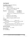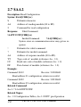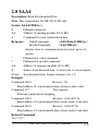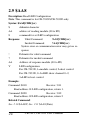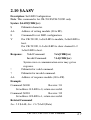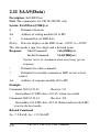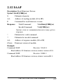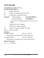
1
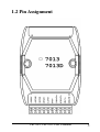
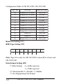
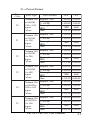
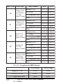
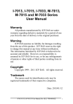
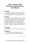
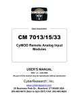
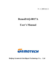
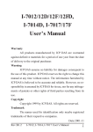
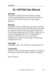
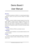
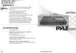
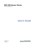
CB-7013, CB-7013D,
&
CB-7033, CB7033D
User’s Manual
Copyright Sept., 2000. All rights are reserved.
CB-7013, CB-7033 User’s Manual
1
Table of Contents
1. Introduction .....................................................4
1.1 More Information .......................................4
1.2 Pin Assignment ..........................................5
1.3 Specifications .............................................7
1.4 Block Diagram ...........................................8
1.5 Wire Connection.........................................9
1.6 Quick Start ...............................................10
1.7 Default Setting .........................................10
1.8 Calibration ...............................................10
1.9 Configuration Tables ................................ 11
2. Command.......................................................15
2.1 %AANNTTCCFF.....................................17
2.2 #** ...........................................................19
2.3 #AA ..........................................................20
2.4 #AAN .......................................................21
2.5 $AA0 ........................................................22
2.6 $AA1 ........................................................23
2.7 $AA2 ........................................................24
2.8 $AA4 ........................................................25
2.9 $AA8 ........................................................26
2.10 $AA8V ...................................................27
2.11 $AA9(Data) ............................................28
2
CB-7013, CB-7033 User’s Manual
2.12 $AAF ......................................................29
2.13 $AAM ....................................................30
2.14 ~AAO(Data)...........................................31
2.15 ~AAEV...................................................32
2.16 ~** .........................................................33
2.17 ~AA0 ......................................................34
2.18 ~AA1 ......................................................35
2.19 ~AA2 ......................................................36
2.20 ~AA3EVV..............................................37
3. Application Notes ..........................................38
3.1 INIT* pin Operation.................................38
3.2 Module Status ..........................................38
3.3 Dual Watchdog Operation ........................39
HM CB COM 7013&33.p65
CB-7013, CB-7033 User’s Manual
3
1. Introduction
CB-7000 is a family of network data acquisition and control
modules. They provide analog-to-digital, digital-to-analog, digital
input/output, timer/counter and other functions. These modules can
be remote-controlled by a set of commands. Common features of
the CB-7013/13D and CB7033/33D are as follows:
l
24-bits sigma-delta ADC for excellent accuracy.
l
RTD direct connection
l
Software calibration
The CB-7013 is a single-channel RTD input module. The
CB-7013D is the CB-7013 with a 4½ digit LED display . The
CB-7033 is a three-channel RTD input module. The CB-7033D is
the CB-7033 with a 4½ digit LED display.
1.1 More Information
Refer to “CB-7000 Bus Converter User Manual” chapter 1 for more information as following:
1.1 CB-7000 Overview
1.2 CB-7000 Related Documentation
1.3 CB-7000 Command Features
1.4 CB-7000 System Network Configuration
1.5 CB-7000 Dimension
4
CB-7013, CB-7033 User’s Manual
1.2 Pin Assignment
CB-7013, CB-7033 User’s Manual
5
6
CB-7013, CB-7033 User’s Manual
1.3 Specifications
CB-7013/CB-7013D
Analog Input
Input Channel: 1
Input Type: 2/3/4-wire RTD
RTD Type:
Pt100 α=0.00385
Pt100 α=0.003916
Ni 120
Pt1000 α=0.00385
(version B1.0 or later)
Sampling Rate:
10 Samples/Second
Bandwidth: 5.24 Hz
Accuracy: ±0.05%
Zero Drift: 0.5µV/°C
Span Drift: 1.0µV/°C
CMR@50/60 Hz: 150dB min
NMR@50/60 Hz: 100dB min
Displayed LED
4½ digits (CB-7013D only)
Power Supply
Input: +10 to +30VDC
Consumption:
0.7 W. for CB-7013
1.3 W. for CB-7013D
CB-7033/CB-7033D
Analog Input
Input Channel: 3
Input Type: 2/3/4-wire RTD
RTD Type:
Pt100 α=0.00385
Pt100 α=0.003916
Ni 120
Pt1000 α=0.00385
Sampling Rate:
15/12.5 Samples/Second
with filter at 60/50Hz
Bandwidth: 15.7 Hz
Accuracy: ±0.1%
Zero Drift: 0.5µV/°C
Span Drift: 1.0µV/°C
CMR@50/60 Hz: 150dB min
NMR@50/60 Hz: 100dB min
Displayed LED
4½ digits (CB-7033D only)
Power Supply
Input: +10 to +30VDC
Consumption:
1.0 W. for CB-7033
1.6 W. for CB-7033D
CB-7013, CB-7033 User’s Manual
7
1.4 Block Diagram
8
CB-7013, CB-7033 User’s Manual
1.5 Wire Connection
2-wire RTD connection
3-wire RTD connection
4-wire RTD connection
CB-7013, CB-7033 User’s Manual
9
1.6 Quick Start
Refer to “ CB-7000 Bus Converter User Manual ” and
“Getting Start” for more detail.
1.7 Default Setting
Default setting for CB-7013/13D, CB-7033/33D:
l
Address: 01
l
RTD Type: Type 20, Pt100, -100°C to 100°C
l
Baud rate: 9600 bps
l
Checksum disable, engineering unit format
l
Filter for 60 Hz rejection
1.8 Calibration
Don’t Do Calibration Until You Understand the Procedure.
Calibration Requirement for CB-7013/13D version A1.x or A2.x.
Type
Zero Calibration Resistor
Span Calibration Resistor
20 to 29
55 ohm
375.0 ohm
Calibration Requirement for CB-7013/13D version B1.0 or later
and CB-7033/33D.
10
Type
Zero Calibration Resistor
Span Calibration Resistor
20 to 29
0 ohm
375.0 ohm
2A
0 ohm
3200.0 ohm
CB-7013, CB-7033 User’s Manual
Calibration Sequence:
1. Connect calibration resistor to module by 4-wire R TD
connection. For CB-7033/33D, connect to channel 0.
2. Warm-Up for 30 minutes.
3. Set Type to 20- Ref. Sec .2.1.
4. Enable Calibration - Ref. Sec. 2.15.
5. Install Zero Calibration Resistor.
6. Preform Zero Calibration Command - Ref. Sec. 2.6.
7. Install Span Calibration Resistor.
8. Perform Span Calibration Command - Ref. Sec. 2.5.
9. Repeat step 4 to step 8 three times.
Note:
1. Step 4 is not needed for CB-7013/13D, version A1.x or A2.x.
2. Same for type 2A only different for set different type (step 3),
and install different Zero/Span Calibration Resistor (step 5, 7).
1.9 Configuration Tables
Code
Baudrate
C ode
Baudrate
03
1200
07
19200
04
2400
08
38400
05
4800
09
57600
06
9600
0A
115200
CB-7013, CB-7033 User’s Manual
11
Configuration Table of CB-7013/13D, CB-7033/33D
Type Code
RTD Type
Temperature Range
20
Platinum 100, a=0.00385
- 100 to 100
21
Platinum 100, a=0.00385
0 to 100
22
Platinum 100, α=0.00385
0 to 200
23
Platinum 100, α=0.00385
0 to 600
24
Platinum 100, α=0.003916
- 100 to 100
25
Platinum 100, α=0.003916
0 to 100
26
Platinum 100, α=0.003916
0 to 200
27
Platinum 100, α=0.003916
0 to 600
28
Nickel 120
- 80 to 100
29
Nickel 120
0 to 100
2A
Platinum 1000, α=0.00385
- 200 to 600
Baud rate Setting (CC)
RTD Type Setting (TT)
7
6
5
4
3
2
*1
*2
0
0
0
0
1
0
*3
Note: Type 2A is only for CB-7013/13D version B1.0 or later and
CB-7033/33D.
Data Format Setting (FF)
*1: Filter Setting 0 = 60 Hz rejection
1 = 50 Hz rejection
*2: Checksum Bit: 0 = Disable, 1 = Enable
*3: 00 = Engineering Unit Format
12
CB-7013, CB-7033 User’s Manual
01 = Percent Format
Type
C ode
RT D Type
20
Platinum 100
α=0.00385
-100 to 100
degree
Celsius
21
22
23
24
25
Platinum 100
α=0.00385
0 to 100
degree
Celsius
Platinum 100
α=0.00385
0 to 200
degree
Celsius
Platinum 100
α=0.00385
0 to 600
degree
Celsius
Platinum 100
α=0.003916
-100 to 100
degree
Celsius
Platinum 100
α=0.003916
0 to 100
degree
Celsius
Da t a For ma t
+F.S.
-F.S.
Engineer Unit
+100.00 -100.00
% of FSR
2's complement
HEX
Ohm
+100.00 -100.00
Engineer Unit
+100.00 +000.00
% of FSR
2's complement
HEX
Ohm
+100.00 +000.00
Engineer Unit
+200.00 +000.00
% of FSR
2's complement
HEX
Ohm
+100.00 +000.00
Engineer Unit
+600.00 +000.00
% of FSR
2's complement
HEX
Ohm
+100.00 +000.00
Engineer Unit
+100.00 -100.00
% of FSR
2's complement
HEX
Ohm
+100.00 -100.00
Engineer Unit
+100.00 +000.00
% of FSR
2's complement
HEX
Ohm
+100.00 +000.00
7FFF
8000
+138.50 +060.60
7FFF
0000
+138.50 +100.00
7FFF
0000
+175.84 +100.00
7FFF
8000
+313.59 +060.60
7FFF
8000
+139.16 +060.60
7FFF
0000
+139.16 +100.00
CB-7013, CB-7033 User’s Manual
13
Type Code
RTD Type
D ata Format
+F.S.
-F.S.
26
Engineer Unit
+200.00 +000.00
Platinum 100
+100.00 +000.00
α=0.003916 % of FSR
0 to 200
2's complement HEX 7FFF
0000
degree Celsius
O hm
+177.13 +100.00
27
Engineer Unit
+600.00 +000.00
Platinum 100
+100.00 +000.00
α=0.003916 % of FSR
0 to 600
2's complement HEX 7FFF
0000
degree Celsius
O hm
+317.28 +100.00
Engineer Unit
+100.00 - 080.00
N ickel 120
% of F S R
+100.00 - 080.00
- 80 to 100
999A
degree Celsius 2's complement HEX 7FFF
O hm
+200.64 +066.60
28
Engineer Unit
+100.00 +000.00
N ickel 120
% of F S R
+100.00 +000.00
0 to 100
0000
degree Celsius 2's complement HEX 7FFF
O hm
+200.64 +120.60
29
Engineer Unit
2A
+600.00 - 200.00
Platinum 1000
% of F S R
+100.00 - 033.33
α=0.00385
- 200 to 600
2's complement HEX 7FFF
AAAA
degree Celsius
O hm
+3137.1 +185.20
10 = 2’s Complement HEX Format
14
O ver Range
Under Range
Engineer's Unit
+9999
- 0000
Percent of FSR
+9999
- 0000
2's Complement HEX
7F F F
8000
CB-7013, CB-7033 User’s Manual
11 = Ohms
2. Command
Command Format; (Leading)(Address)(Command)[CHK](cr)
Response Format: (Leading)(Address)(Data)[CHK](cr)
[CHK] 2-character checksum
(cr)
end-of-command character, character return (0x0D)
Calculate Checksum:
1. Calculate ASCII sum of all characters of command (or
response) string except the character return (cr).
2. Mask the sum of string with 0ffh.
Example:
Command string: $012(cr)
Sum of string = ‘$’+‘0’+‘1’+‘2’ = 24h+30h+31h+32h = B7h.
The checksum is B7h, and [CHK] = “B7”.
Command string with checksum: $012B7(cr).
Response string: !01200600(cr).
Sum of string: ‘!’+‘0’+‘1’+‘2’+‘0’+‘0’+‘6’+‘0’+‘0’
= 21h+30h+31h+32h+30h+30h+36h+30h+30h = 1AAh
The checksum is AAh, and [CHK] = “AA”.
Response string with checksum: !01200600AA(cr).
CB-7013, CB-7033 User’s Manual
15
Ge ne ral Command Se ts
Command
Re s pons e
De s cription
Se ction
%AANNTTCCFF !AA
Set Module Configuration
Sec.2.1
#**
No Response
Synchronized Sampling
Sec.2.2
#AA
>(Data)
Read Analog Input
Sec.2.3
#AAN
>(Data)
Read Analog Input from
channel N
Sec.2.4
$AA0
!AA
Perform Span Calibration
Sec.2.5
$AA1
!AA
Perform Zero Calibration
Sec.2.6
$AA2
!AANNTTCCFF Read Configuration
Sec.2.7
$AA4
>AAS(Data)
Read Synchronized Data
Sec.2.8
$AA8
!AAV
Read LED Configuration
Sec.2.9
$AA8V
!AA
Set LED Configuration
Sec.2.10
$AA9(Data)
!AA
Set LED Data
Sec.2.11
$AAF
!AA(Data)
Read Firmware Version
Sec.2.12
$AAM
!AA(Data)
Read Module Name
Sec.2.13
~AAO(Data)
!AA
Set Module Name
Sec.2.14
~AAEV
!AA
Enable/Disable Calibration Sec.2.15
Hos t Watchdog Command Se ts
Command
Re s pons e
De s cription
Se ction
~ **
No Response
Host OK
Sec.2.16
~AA0
!AASS
Read Module Status
Sec.2.17
~AA1
!AA
Reset Module Status
Sec.2.18
~AA2
!AATT
Read Host Watchdog
Timeout Value
Sec.2.19
~AA3ETT
!AA
Set Host Watchdog
Timeout Value
Sec.2.20
16
CB-7013, CB-7033 User’s Manual
2.1 %AANNTTCCFF
Description: Set module configuration
Syntax: %AANNTTCCFF[CHK](cr)
%
A delimiter character.
AA
Address of setting module(00 to FF).
NN
New address for setting module(00 to FF).
TT
New type for setting module (Ref Sec. 1.9).
CC
New baud rate for setting module (Ref Sec. 1.9). It is
needed to short the INIT* to ground while change baud
rate. (Ref Sec. 3.1).
FF
New data format for setting module (Ref Sec. 1.9). It is
needed to short the INIT* to ground to change checksum
setting (Ref Sec. 3.1).
Response:
Valid Command:
!AA[CHK](cr)
Invalid Command:
?AA[CHK](cr)
Syntax error or communication error may get no response.
!
Delimiter for valid command.
?
Delimiter for invalid command. While change baudrate
or checksum setting without short INIT* to ground, the
module will return invalid command.
AA
Address of response module(00 to FF)
Example:
Command: %0102200600
Receive: !02
Change address from 01 to 02, return successful.
CB-7013, CB-7033 User’s Manual
17
Command: %0202200603
Receive: !02
Change data format from 00 to 03, return successful.
Related Command:
Sec. 2.7 $AA2
Related Topics:
Sec. 1.9 Configuration Tables, Sec. 3.1 INIT* pin Operation.
18
CB-7013, CB-7033 User’s Manual
2.2 #**
Description: Synchronized Sampling
Syntax: #**[CHK](cr)
#
A delimiter character.
**
Synchronized sampling command.
Response:
No response
Example:
Command:
#**
No response
Send synchronized sampling command.
Command: $014
Receive: >011+025.123
First read, get status=1
Command: $014
Receive: >010+025.123
Second read, get status=0
Related Command:
Sec. 2.8 $AA4
Note: The command is for CB-7013/13D only.
CB-7013, CB-7033 User’s Manual
19
2.3 #AA
Description: Read Analog Input
Syntax: #AA[CHK](cr)
#
Delimiter character
AA
Address of reading module(00 to FF)
Response:
Valid Command: >(Data)[CHK](cr)
Syntax error or communication error may get no
response.
>
Delimiter for valid command.
(Data) Analog input value, reference Sec. 1.9 for its format
While using #AA command to CB-7033/33D, the data is
the combination for each channel respectively.
Example:
Command: #01
Receive: >+026.35
Read address 01, get data successfully.
Command: #02
Receive: >4C53
Read address 02, get data in HEX format successfully.
Command: #03
Receive: >-0000
Read address 03, get data underrange.
Command: #04
Receive: >+025.12+054.12+150.12
Read address 04, is I7033/I7033D, get 3 channel data.
Related Command:
Sec2.1 %AANNTTCCFF, Sec. 2.7 $AA2
Related Topics:
Sec. 1.9 Configuration Tables
20
CB-7013, CB-7033 User’s Manual
2.4 #AAN
Description: Read Analog Input from channel N
Syntax: #AAN[CHK](cr)
#
Delimiter character
AA
Address of reading module (00 to FF).
N
Channel to read.
Response:
Valid Command:
>(Data)[CHK](cr)
Invalid Command:
?AA[CHK](cr)
Syntax error or communication error may get no response.
>
Delimiter for valid command.
(Data) Analog input value, reference Sec. 1.9 for its format.
?
Delimiter for invalid command.
AA
Address of response module (00 to FF).
Example:
Command: #032
Receive: >+025.13
Read address 03 channel 2, get data successfully.
Command: #024
Receive: ?02
Read address 02 channel 4, return error channel number
Related Command:
Sec2.1 %AANNTTCCFF, Sec. 2.7 $AA2
Related Topics:
Sec. 1.9 Configuration Tables
Note: The command for CB-7033/33D only.
CB-7013, CB-7033 User’s Manual
21
2.5 $AA0
Description: Perform Span Calibration
Syntax: $AA0[CHK](cr)
$
Delimiter character
AA
Address of setting module (00 to FF)
0
Command for span calibration
Response:
Valid Command:
!AA[CHK](cr)
Invalid Command:
?AA[CHK](cr)
Syntax error or communication error may get no response.
!
Delimiter for valid command.
?
Delimiter for invalid command.
AA
Address of response module (00 to FF).
Example:
Command: $010
Receive: !01
Perform address 01 span calibration, return successful.
Command: $020
Receive: ?02
When performing address 02 zero calibration, return was not
enabled before performing calibration command.
Related Command:
Sec2.6 $AA1, Sec. 2.15 ~AAEV
Related Topics:
Sec. 1.8 Calibration
22
CB-7013, CB-7033 User’s Manual
2.6 $AA1
Description: Perform Zero Calibration
Syntax: $AA1[CHK](cr)
$
Delimiter character.
AA
Address of setting module (00 to FF)
1
Command for zero calibration.
Response:
Valid Command:
!AA[CHK](cr)
Invalid Command:
?AA[CHK](cr)
Syntax error or communication error may get no
response.
!
Delimiter for valid command.
?
Delimiter for invalid command.
AA
Address of response module (00 to FF).
Example:
Command: $011
Receive: !01
Preform address 01 zero calibration, return successful.
Command: $021
Receive: ?02
When performing address 02 zero calibration, return was
not enabled before performing calibration command.
Related Command:
Sec2.5 $AA0, Sec. 2.15 ~AAEV
Related Topics:
Sec. 1.8 Calibration
CB-7013, CB-7033 User’s Manual
23
2.7 $AA2
Description: Read Configuration
Syntax: $AA2[CHK](cr)
$
Delimiter character
AA
Address of reading module (00 to FF)
2
Command for read configuration
Response:
Valid Command:
!AATTCCFF[CHK](cr)
Invalid Command:
?AA[CHK](cr)
Syntax error or communication error may get no response.
!
Delimiter for valid command.
?
Delimiter for invalid command.
AA
Address of response module (00 to FF).
TT
Type code of module (reference Sec. 1.9).
CC
Baud rate code of module (reference Sec. 1.9).
FF
Data format of module (reference Sec. 1.9).
Example:
Command: $012
Receive: !01200600
Read address 01 configuration, return successful
Command: $022
Receive: !02230602
Read address 02 configuration, return successful.
Related Command:
Sec2.1 %AANNTTCCFF
Related Topics:
Sec. 1.9 Configuration Tables, Sec3.1 INIT* pin Operation.
24
CB-7013, CB-7033 User’s Manual
2.8 $AA4
Description: Read Synchronized Data
Note: This command is for CB-7013/13D only.
Syntax: $AA4[CHK](cr)
$
Delimiter character.
AA
Address of reading module (00 to FF).
4
Command for read synchronized data.
Response:
Valid Command:
>AAS(Data)[CHK](cr)
Invalid Command:
?AA[CHK](cr)
Syntax error or communication error may get no response.
!
Delimiter for valid command.
?
Delimiter for invalid command.
AA
Address of response module (00 to FF).
S
Status of synchronized data, 1 = first read, 0 = been readed
(Data) Synchronized data, format reference Sec.1.9.
Example:
Command: $014
Receive: ?01
Read address 01 synchronized data, return no data valid
Command: #**
No response
Perform synchronized sampling
Command: $014
Receive: >011+025.56
Read address 01 synchronized data, return status 1 and data.
Command: $014
Receive: >010+25.56
Read address 01 synchronized data, return status 0 and data.
Related Command:
Sec2.2 #**
.
CB-7013, CB-7033 User’s Manual
25
2.9 $AA8
Description: Read LED Configuration
Note: This command is for CB-7013D/CB-7033D only.
Syntax: $AA8[CHK](cr)
$
delimiter character
AA
address of reading module (00 to FF)
8
command for set LED configuration
Response:
Valid Command:
!AAV[CHK](cr)
Invalid Command:
?AA[CHK](cr)
Syntax error or communication error may get no response.
!
Delimiter for valid command
?
Delimiter for invalid command
AA
Address of response module (00 to FF)
V
LED configuration
For CB-7013D, 1=module control, 2=host control
For CB-7033D, 0~2=LED show channel 0~2,
3=LED is host control
Example:
Command: $018
Receive: !011
Read address 01 LED configuration, return 1.
Command: $028
Receive: !012
Read address 02 LED configuration, return 2
Related Command:
Sec. 2.10 $AA8V, Sec. 2.11 $AA9(Data)
26
CB-7013, CB-7033 User’s Manual
2.10 $AA8V
Description: Set LED Configuration
Note: This command is for CB-7013D/CB-7033D only.
Syntax: $AA8V[CHK](cr)
$
Delimiter character.
AA
Address of setting module (00 to FF).
8
Command for set LED configuration.
V
For CB-7013D, 1=Set LED to module, 2=Set LED to
host.
For CB-7033D, 0~2=Set LED to show channel 0~2
3=Set LED to host.
Response:
Valid Command:
!AA[CHK](cr)
Invalid Command:
?AA[CHK](cr)
Syntax error or communication error may get no
response.
!
Delimiter for valid command.
?
Delimiter for invalid command.
AA
Address of response module (00 to FF).
Example:
Command: $0180
Receive: !01
Set address 01 LED to 0, return successful
Command: $0281
Receive: !02
Set address 02 LED to 1, return successful
Related Command:
Sec. 2.9 $AA8, Sec. 2.11 $AA9(Data)
CB-7013, CB-7033 User’s Manual
27
2.11 $AA9(Data)
Description: Set LED Data
Note: The command is for CB-7013D/33D only.
Syntax: $AA9(Data)[CHK](cr)
$
Delimiter character
AA
Address of setting module (00 to FF)
9
Command for set LED data
(Data) Data for display on the LED, from −19999. to +19999.
The data needs a sign, five digits and a decimal point.
Response:
Valid Command:
!AA[CHK](cr)
Invalid Command:
?AA[CHK](cr)
Syntax error or communication error may get no
response.
!
Delimiter for valid command.
?
Delimiter for invalid command or LED not set to host
control.
AA
Address of response module (00 to FF)
Example:
Command: $019+123.45
Receive: !01
Send address 01 LED data +123.45, return successful
Command: $029+512.34
Receive: ?02
Send address 02, LED data +512.34. Return indicates the LED
is not in the host mode.
Related Command:
Sec. 2.9 $AA8, Sec. 2.10 $AA8V
28
CB-7013, CB-7033 User’s Manual
2.12 $AAF
Description: Read Firmware Version
Syntax: $AAF[CHK](cr)
$
Delimiter character
AA
Address of reading module (00 to FF)
F
Command for read firmware version
Response:
Valid Command:
!AA(Data)[CHK](cr)
Invalid Command:
?AA[CHK](cr)
Syntax error or communication error may get no
response.
!
Delimiter for valid command.
?
Delimiter for invalid command.
AA
Address of response module (00 to FF)
(Data) Firmware version of module.
Example:
Command: $01F
Receive: !01A2.0
Read address 01 firmware version, returns version A2.0.
Command: $02F
Receive: !01B1.1
Read address 02 firmware version, returns version B1.1.
CB-7013, CB-7033 User’s Manual
29
2.13 $AAM
Description: Read Module Name
Syntax: $AAM[CHK](cr)
$
Delimiter character
AA
Address of reading module (00 to FF)
M
Command for read module name
Response:
Valid Command:
!AA(Data)[CHK](cr)
Invalid Command:
?AA[CHK](cr)
Syntax error or communication error may get no response.
!
Delimiter for valid command.
?
Delimiter for invalid command.
AA
Address of response module (00 to FF)
(Data) Name of module.
Example:
Command: $01M
Receive: !017013
Read address 01 module name, returns name 7013.
Command: $03M
Receive: !037033D
Read address 03 module name, returns name 7033D.
Related Command:
Sec. 2.14 ~AAO(Data)
30
CB-7013, CB-7033 User’s Manual
2.14 ~AAO(Data)
Description: Set Module Name
Syntax: ~AAO(Data)[CHK](cr)
~
Delimiter character
AA
Address of setting module (00 to FF)
O
Command for set module name
(Data) New name for module, maximum six characters
Response:
Valid Command:
!AA[CHK](cr)
Invalid Command:
?AA[CHK](cr)
Syntax error or communication error may get no response.
!
Delimiter for valid command.
?
Delimiter for invalid command.
AA
Address of response module (00 to FF).
Example:
Command: ~01O7013
Receive: !01
Set address 01 module name to 7013, returns successful.
Command: $01M
Receive: !017013
Read address 01 module name, returns 7013.
Related Command:
Sec. 2.12 $AAM
CB-7013, CB-7033 User’s Manual
31
2.15 ~AAEV
Description: Enable/Disable Calibration
Syntax: ~AAEV[CHK](cr)
~
Delimiter character
AA
Address of setting module (00 to FF)
E
Command for enable/disable calibration
V
1=Enable/0=Disable calibration
Response:
Valid Command:
!AA[CHK](cr)
Invalid Command:
?AA[CHK](cr)
Syntax error or communication error may get no
response.
!
Delimiter for valid command.
?
Delimiter for invalid command.
AA
Address of response module (00 to FF).
Example:
Command: $010
Receive: ?01
Perform addreess 01 span calibration, return not enable
calibration.
Command: ~01E1
Receive: !01
Set address 01 to enable calibration, returns successful.
Command: $010
Receive: !01
Preform address 01 span calibration, returns successful.
Related Command:
Sec. 2.5, $AA0; Sec. 2.6, $AA1
Related Topic:
Sec. 1.8, Calibration
32
CB-7013, CB-7033 User’s Manual
2.16 ~**
Description: Host OK.
Host send this command to all modules for send the information
“Host OK”.
Syntax: ~**[CHK](cr)
~
delimiter character.
**
command for all modules.
Response:
No response.
Example:
Command: ~**
No response
Send Host OK to all modules.
Related Command:
Sec. 2.17 ~AA0, Sec. 2.18 ~AA1, Sec. 2.19 ~AA2, Sec. 2.20
~AA3EVV
Related Topic:
Sec. 3.2, Module Status; Sec. 3.3, Dual Watchdog Operation
CB-7013, CB-7033 User’s Manual
33
2.17 ~AA0
Description: Read Module Status
Syntax: ~AA0[CHK](cr)
~
Delimiter character
AA
Address of reading module (00 to FF)
0
Command for read module status
Response:
Valid Command:
!AASS[CHK](cr)
Invalid Command:
?AA[CHK](cr)
Syntax error or comm. error may get no response.
!
Delimiter for valid command.
?
Delimiter for invalid command.
AA
Address of response module (00 to FF).
SS
host watchdog time-out status, 00=status is clear ,
04=status is set. The status will store into EEPROM and
only may reset by the command ~AA1.
Example:
Command: ~010
Receive: !0100
Read address 01 module status, return 00.
Command: ~020
Receive: !0204
Read address 02 module status. A return of 04, means the
host watchdog time-out status is set; module is in safe mode.
Related Command:
Sec. 2.16 ~**, Sec. 2.18 ~AA1, Sec. 2.19 ~AA2,
Sec. 2.20 ~AA3EVV
Related Topic: Sec. 3.2, Module Status; Sec. 3.3, Dual Watchdog
Operation
34
CB-7013, CB-7033 User’s Manual
2.18 ~AA1
Description: Reset Module Status
Syntax: ~AA1[CHK](cr)
~
Delimiter character
AA
Address of setting module (00 to FF)
1
Command for reset module status
Response:
Valid Command:
!AA[CHK](cr)
Invalid Command:
?AA[CHK](cr)
Syntax error or comm. error may get no response.
!
Delimiter for valid command.
?
Delimiter for invalid command.
AA
Address of response module (00 to FF).
Example:
Command: ~010
Receive: !0104
Read address 01 module status, return 04, host watchdog
time-out.
Command: ~011
Receive: !01
Reset address 01 module status, return successful.
Command: ~010
Receive: !0100
Read address 01 module status, return 00, no host watchdog
time-out.
Related Command:
Sec. 2.16 ~**, Sec. 2.17 ~AA0, Sec. 2.19 ~AA2, Sec. 2.20
~AA3EVV
Related Topic:
Sec. 3.2, Module Status; Sec. 3.3, Dual Watchdog Operation
CB-7013, CB-7033 User’s Manual
35
2.19 ~AA2
Description: Read Host Watchdog Time-out Value
Syntax: ~AA2[CHK](cr)
~
Delimiter character.
AA
Address of reading module (00 to FF).
2
Command for read host watchdog time-out value.
Response:
Valid Command:
!AAVV[CHK](cr)
Invalid Command:
?AA[CHK](cr)
Syntax error or communication error may get no
response.
!
Delimiter for valid command.
?
Delimiter for invalid command.
AA
Address of response module (00 to FF).
VV
Time-out value in HEX format, count for 0.1 second
01=0.1 second and FF=25.5 second.
Example:
Command: ~012
Receive: !01FF
Read address 01 host watchdog time-out value. On return of
FF, the host watchdog time-out value is 25.5 second.
Related Command:
Sec. 2.16 ~**, Sec. 2.17 ~AA0, Sec. 2.18 ~AA1, Sec. 2.20
~AA3EVV
Related Topic:
Sec. 3.2, Module Status; Sec. 3.3, Dual Watchdog Operation
36
CB-7013, CB-7033 User’s Manual
2.20 ~AA3EVV
Description: Set Host Watchdog Time-out Value
Syntax: ~AA3EVV[CHK](cr)
~
Delimiter character.
AA
Address of setting module (00 to FF).
3
command for set host watchdog time-out value.
E
1=Enable/0=Disable host watchdog.
VV
Time-out value, from 01 to FF, each for 0.1 second.
Response:
Valid Command:
!AA[CHK](cr)
Invalid Command:
?AA[CHK](cr)
Syntax error or communication error may get no
response.
!
Delimiter for valid command.
?
Delimiter for invalid command.
AA
Address of response module (00 to FF).
Example:
Command: ~013164
Receive: !01
Set address 01 enables host watchdog and time-out value is
set to 64 (10.0 seconds); returns successful.
Command: ~012
Receive: !0164
Read address 01 host watchdog time-out value. Return 64,
the time-out value is 10.0 seconds.
Related Command:
Sec. 2.16 ~**, Sec. 2.17 ~AA0, Sec. 2.18 ~AA1, Sec. 2.19 ~AA2
Related Topic:
Sec. 3.2 Module Status; Sec. 3.3, Dual Watchdog Operation
CB-7013, CB-7033 User’s Manual
37
3. Application Note
3.1 INIT* pin Operation
Each CB-7000 module has a build-in EEPROM to store
configuration information such as address, type, baud rate, and other
information. Sometimes, a user may forget the configuration of the
module. Therefore, the CB-7000 modules have a special mode
named “INIT mode”, to help user to resolve the problem. The
“INIT mode” is setting as Address=00, baud rate=9600 bps, no
checksum
To enable INIT mode, do the following steps:
Step 1. Power-off the module.
Step 2. Connect the INIT* pin to the GND pin.
Step 3. Turn power on.
Step 4. Send command $002(cr) at 9600 bps to read the
configuration stored in the module’s EEPROM.
Refer to “7000 Bus Converter User Manual” Sec. 5.1
and “Getting Started” for more information.
3.2 Module Status
Power-On Reset or Module Watchdog Reset will put all
outputs to Power-On Value. And the module may accept the host’s
command to change the output value.
Host Watchdog Time-out will cause all digital outputs to
go to their Safe Value. The module’s status (read by command
~AA0) will be 04, and the output command will be ignored.
38
CB-7013, CB-7033 User’s Manual
3.3 Dual Watchdog Operation
Dual Watchdog = Module Watchdog + Host Watchdog
The Module Watchdog is a hardware reset circuit to
monitor the module’s operating status. While working in harsh or
noisy environment, the module may go down by the external noise
signal. The circuit may let the module to work continues and never
halt.
The Host Watchdog is a software function to monitor the
host’s operating status. Its purpose is to detect a network/communication problem or host halt. When a time-out occurs, the
module changes all outputs to the safe state to prevent
possible dangerous problems of a controlled unit/process.
The CB-7000 module with Dual W atchdog makes the
control system more reliable and stable.
CB-7013, CB-7033 User’s Manual
39
For your notes.
40
CB-7013, CB-7033 User’s Manual
For your notes.
CB-7013, CB-7033 User’s Manual
41
For your notes.
42
CB-7013, CB-7033 User’s Manual
EC Declaration of Conformity
We, Measurement Computing Corporation, declare under sole
responsibility that the product:
CB-7013/CB-7013D,
CB-7033/CB-7033D
Part Number
RTD Input Modules
Description
to which this declaration relates, meets the essential requirements,
is in conformity with, and CE marking has been applied according to the relevant EC Directives listed below using the relevant
section of the following EC standards and other normative documents:
EU EMC Directive 89/336/EEC: Essential requirements relating to electromagnetic compatibility.
EU 55022 Class B: Limits and methods of measurements of
radio interference characteristics of information technology
equipment.
EN 50082-1: EC generic immunity requirements.
IEC 801-2: Electrostatic discharge requirements for industrial
process measurement and control equipment.
IEC 801-3: Radiated electromagnetic field requirements for industrial process measurements and control equipment.
IEC 801-4: Electrically fast transients for industrial process measurement and control equipment.
Carl Haapaoja, Director of Quality Assurance
CB-7013, CB-7033 User’s Manual
43
Measurement Computing Corporation
10 Commerce Way
Suite 1008
Norton, Massachusetts 02766
(508) 946-5100
Fax: (508) 946-9500
E-mail: [email protected]
www.mccdaq.com