1
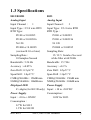
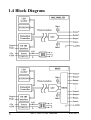
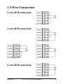
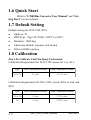
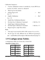
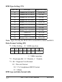
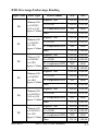
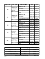
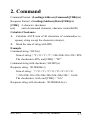
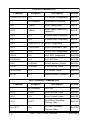
8013,8013D, 8033
User Manual
Warranty
All products manufactured by SuperLogics are warranted
against defective materials for a period of one year from the date
of delivery to the original purchaser.
Warning
SuperLogics assume no liability for damages consequent
to the use of this product. SuperLogics reserves the right to change
this manual at any time without notice. The information furnished
by SuperLogics is believed to be accurate and reliable. However,
no responsibility is assumed by SuperLogics for its use, nor for any
infringements of patents or other rights of third parties resulting
from its use.
Copyright
Copyright 1999 by SuperLogics. All rights are reserved.
Trademark
The names used for identification only maybe registered
trademarks of their respective companies.
Date:2000-04
Rev:B1.2
8013, 8033 User Manual
1
Table of Contents
1. Introduction .....................................................4
1.1 More Information.......................................4
1.2 Pin Assignment ..........................................5
1.3 Specifications ............................................7
1.4 Block Diagram ..........................................8
1.5 Wire Connection........................................9
1.6 Quick Start ..............................................10
1.7 Default Setting ........................................10
1.8 Calibration ...............................................10
1.9 Configuration Tables ...............................11
2. Command .......................................................15
2.1 %AANNTTCCFF ...................................17
2.2 #** ...........................................................19
2.3 #AA .........................................................20
2.4 #AAN ......................................................21
2.5 $AA0 .......................................................22
2.6 $AA1 .......................................................23
2.7 $AA2 .......................................................24
2.8 $AA4 .......................................................25
2.9 $AA8 .......................................................26
2.10 $AA8V ..................................................27
2.11 $AA9(Data) ...........................................28
2
8013, 8033 User Manual
Rev:B1.2
2.12 $AAF .....................................................29
2.13 $AAM....................................................30
2.14 ~AAO(Data) ..........................................31
2.15 ~AAEV ..................................................32
2.16 ~** .........................................................33
2.17 ~AA0 .....................................................34
2.18 ~AA1 .....................................................35
2.19 ~AA2 .....................................................36
2.20 ~AA3EVV .............................................37
3. Application Note............................................38
3.1 INIT* pin Operation ................................38
3.2 Module Status..........................................38
3.3 Dual Watchdog Operation .......................39
Rev:B1.2
8013, 8033 User Manual
3
1. Introduction
8000 is a family of network data acquisition and control
modules. They provide analog-to-digital, digital-to-analog, digital
input/output, timer/counter and other functions. These modules
can be remote controlled by a set of commands. The common features of 8013/13D and 8033 are given as following :
!
24-bits sigma-delta ADC to provide excellent accuracy.
!
RTD direct connect
!
Software calibration
The 8013 is a single channel RTD input module. The 8013D
is the 8013 with a 4½ digit LED display. The 8033 is a three channel RTD input module.
1.1 More Information
Refer to “8000 Bus Converter User Manual” chapter 1
for more information as following:
1.1 8000 Overview
1.2 8000 Related Documentation
1.3 8000 Command Features
1.4 8000 System Network Configuration
1.5 8000 Dimension
4
8013, 8033 User Manual
Rev:B1.2
1.2 Pin Assignment
Rev:B1.2
8013, 8033 User Manual
5
6
8013, 8033 User Manual
Rev:B1.2
1.3 Specifications
8013/8013D
Analog Input
Input Channel :
1
Input Type : 2/3/4 wire RTD
RTD Type :
Pt100 α=0.00385
Pt100 α=0.003916
Ni 120
Pt1000 α=0.00385
(version B1.0 or later)
Sampling Rate :
10 Samples/Second
Bandwidth : 5.24 Hz
Accuracy : ±0.05%
Zero Drift : 0.5µV/°C
Span Drift : 1.0µV/°C
CMR@50/60Hz : 150dB min
NMR@50/60Hz : 100dB min
Displayed LED
4½ digits (for 8013D only)
Power Supply
Input : +10 to +30VDC
Consumption :
0.7W for 8013
1.3W for 8013D
Rev:B1.2
8033
Analog Input
Input Channel :
3
Input Type : 2/3/4 wire RTD
RTD Type :
Pt100 α=0.00385
Pt100 α=0.003916
Ni 120
Pt1000 α=0.00385
Sampling Rate :
15/12.5 Samles/Second
while filter at 60/50Hz
Bandwidth : 15.7 Hz
Accuracy : ±0.1%
Zero Drift : 0.5µV/°C
Span Drift : 1.0µV/°C
CMR@50/60Hz : 150dB min
NMR@50/60Hz : 100dB min
Power Supply
Input : +10 to +30VDC
Consumption :
1.0W for 8033
8013, 8033 User Manual
7
1.4 Block Diagram
8
8013, 8033 User Manual
Rev:B1.2
1.5 Wire Connection
2-wire RTD connection
3-wire RTD connection
4-wire RTD connection
Rev:B1.2
8013, 8033 User Manual
9
1.6 Quick Start
Refer to “I-7000 Bus Converter User Manual” and “Getting Start” for more detail.
1.7 Default Setting
Default setting for 8013/13D, 8033 :
!
Address : 01
!
RTD Type : Type 20, Pt100, -100°C to 100°C
!
Baudrate : 9600 bps
!
Checksum disable, engineer unit format
!
Filter at 60Hz rejection
1.8 Calibration
Don’t Do Calibrate Until You Realy Understand.
Calibration Requirement for 8013/13D version A1.x or A2.x
Type
Zero Calibration Resistor
Span Calibration Resistor
20 to 29
55 ohm
375.0 ohm
Calibration Requirement for 8013/13D version B1.0 or later and
8033
10
Type
Zero Calibration Resistor
Span Calibration Resistor
20 to 29
0 ohm
375.0 ohm
2A
0 ohm
3200.0 ohm
8013, 8033 User Manual
Rev:B1.2
Calibration Sequence :
1
Connect calibration resistor to module by 4-wire RTD connection. For 8033, connect to channel 0
2
Warm-Up for 30 minutes
3
Setting Type to 20
-> Ref
Sec.2.1.
4
Enable Calibration
-> Ref
Sec.2.15.
5
Install Zero Calibration Resistor
6
Preform Zero Calibration Command
-> Ref Sec.2.6.
7
Install Span Calibration Resistor
8
Perform Span Calibration Command
-> Ref Sec.2.5.
9
Repeat step4 to step8 three times.
Note :
1
The step 4 is not need for 8013/13D version A1.x or A2.x.
2 Do for type 2A only different for set different type(step3),
and install different Zero/Span Calibration Resistor(step5,7).
1.9 Configuration Tables
Configuration Table of I-7013/13D, I-7033/33D
Baudrate Setting (CC)
Rev:B1.2
C ode
Baudrate
C ode
Baudrate
03
1200
07
19200
04
2400
08
38400
05
4800
09
57600
06
9600
0A
115200
8013, 8033 User Manual
11
RTD Type Setting (TT)
Type Code
RTD Type
Temperature Range
20
Platinum 100, a=0.00385
- 100 to 100
21
Platinum 100, a=0.00385
0 to 100
22
Platinum 100, α=0.00385
0 to 200
23
Platinum 100, α=0.00385
0 to 600
24
Platinum 100, α=0.003916
- 100 to 100
25
Platinum 100, α=0.003916
0 to 100
26
Platinum 100, α=0.003916
0 to 200
27
Platinum 100, α=0.003916
0 to 600
28
Nickel 120
- 80 to 100
29
Nickel 120
0 to 100
2A
Platinum 1000, α=0.00385
- 200 to 600
Note : Type 2A only for 8013/13D version B1.0 or later and 8033.
Data Format Setting (FF)
*1 : Filter Setting 0 = 60Hz rejection
7
6
*1 *2
5
4
3
2
0
0
0
0
1
0
*3
1 = 50Hz rejection
*2 : Checksum Bit : 0 = Disable, 1 = Enable
*3 : 00 = Engineer Unit Format
01 = Percent Format
10 = 2’s Complement HEX Format
11 = Ohms
RTD type and data format table
12
8013, 8033 User Manual
Rev:B1.2
RTD Overrange/Underrange Reading
Type Code
RTD Type
D ata Format
Engineer Unit
+F.S.
-F.S.
+100.00 - 100.00
20
Platinum 100
% of F S R
+100.00 - 100.00
α=0.00385
- 100 to 100
2's complement HEX 7FFF
8000
degree Celsius
O hm
+138.50 +060.60
21
Engineer Unit
+100.00 +000.00
Platinum 100
% of F S R
+100.00 +000.00
α=0.00385
0 to 100
2's complement HEX 7FFF
0000
degree Celsius
O hm
+138.50 +100.00
Engineer Unit
+200.00 +000.00
22
Platinum 100
% of F S R
+100.00 +000.00
α=0.00385
0 to 200
2's complement HEX 7FFF
0000
degree Celsius
O hm
+175.84 +100.00
23
Engineer Unit
+600.00 +000.00
Platinum 100
% of F S R
+100.00 +000.00
α=0.00385
0 to 600
2's complement HEX 7FFF
8000
degree Celsius
O hm
+313.59 +060.60
24
Engineer Unit
+100.00 - 100.00
Platinum 100
+100.00 - 100.00
α=0.003916 % of FSR
- 100 to 100
2's complement HEX 7FFF
8000
degree Celsius
O hm
+139.16 +060.60
25
Engineer Unit
+100.00 +000.00
Platinum 100
+100.00 +000.00
α=0.003916 % of FSR
0 to 100
2's complement HEX 7FFF
0000
degree Celsius
O hm
+139.16 +100.00
Rev:B1.2
8013, 8033 User Manual
13
Type Code
RTD Type
D ata Format
-F.S.
26
Engineer Unit
+200.00 +000.00
Platinum 100
+100.00 +000.00
α=0.003916 % of FSR
0 to 200
2's complement HEX 7FFF
0000
degree Celsius
O hm
+177.13 +100.00
27
Engineer Unit
+600.00 +000.00
Platinum 100
+100.00 +000.00
α=0.003916 % of FSR
0 to 600
2's complement HEX 7FFF
0000
degree Celsius
O hm
+317.28 +100.00
Engineer Unit
+100.00 - 080.00
N ickel 120
% of F S R
+100.00 - 080.00
- 80 to 100
999A
degree Celsius 2's complement HEX 7FFF
O hm
+200.64 +066.60
28
Engineer Unit
+100.00 +000.00
N ickel 120
% of F S R
+100.00 +000.00
0 to 100
0000
degree Celsius 2's complement HEX 7FFF
O hm
+200.64 +120.60
29
Engineer Unit
2A
14
+F.S.
+600.00 - 200.00
Platinum 1000
% of F S R
+100.00 - 033.33
α=0.00385
- 200 to 600
2's complement HEX 7FFF
AAAA
degree Celsius
O hm
+3137.1 +185.20
O ver Range
Under Range
Engineer's Unit
+9999
- 0000
Percent of FSR
+9999
- 0000
2's Complement HEX
7F F F
8000
8013, 8033 User Manual
Rev:B1.2
2. Command
Command Format : (Leading)(Address)(Command)[CHK](cr)
Response Format : (Leading)(Address)(Data)[CHK](cr)
[CHK] 2-character checksum
(cr)
end-of-command character, character return(0x0D)
Calculate Checksum :
1. Calculate ASCII sum of all characters of command(or response) string except the character return(cr).
2. Mask the sum of string with 0ffh.
Example :
Command string : $012(cr)
Sum of string = ‘$’+‘0’+‘1’+‘2’ = 24h+30h+31h+32h = B7h
The checksum is B7h, and [CHK] = “B7”
Command string with checksum : $012B7(cr)
Response string : !01200600(cr)
Sum of string : ‘!’+‘0’+‘1’+‘2’+‘0’+‘0’+‘6’+‘0’+‘0’
= 21h+30h+31h+32h+30h+30h+36h+30h+30h = 1AAh
The checksum is AAh, and [CHK] = “AA”
Response string with checksum : !01200600AA(cr)
Rev:B1.2
8013, 8033 User Manual
15
Ge ne ral Command Se ts
Command
Re s pons e
De s cription
Se ction
%AANNTTCCFF !AA
Set Module Configuration
Sec.2.1
#**
No Response
Synchronized Sampling
Sec.2.2
#AA
>(Data)
Read Analog Input
Sec.2.3
#AAN
>(Data)
Read Analog Input from
channel N
Sec.2.4
$AA0
!AA
Perform Span Calibration
Sec.2.5
$AA1
!AA
Perform Zero Calibration
Sec.2.6
$AA2
!AANNTTCCFF Read Configuration
Sec.2.7
$AA4
>AAS(Data)
Read Synchronized Data
Sec.2.8
$AA8
!AAV
Read LED Configuration
Sec.2.9
$AA8V
!AA
Set LED Configuration
Sec.2.10
$AA9(Data)
!AA
Set LED Data
Sec.2.11
$AAF
!AA(Data)
Read Firmware Version
Sec.2.12
$AAM
!AA(Data)
Read Module Name
Sec.2.13
~AAO(Data)
!AA
Set Module Name
Sec.2.14
~AAEV
!AA
Enable/Disable Calibration Sec.2.15
Hos t Watchdog Command Se ts
Command
Re s pons e
De s cription
Se ction
~ **
No Response
Host OK
Sec.2.16
~AA0
!AASS
Read Module Status
Sec.2.17
~AA1
!AA
Reset Module Status
Sec.2.18
~AA2
!AATT
Read Host Watchdog
Timeout Value
Sec.2.19
~AA3ETT
!AA
Set Host Watchdog
Timeout Value
Sec.2.20
16
8013, 8033 User Manual
Rev:B1.2
2.1 %AANNTTCCFF
Description : Set module Configuration
Syntax : %AANNTTCCFF[CHK](cr)
%
a delimiter character
AA
address of setting module(00 to FF)
NN
new address for setting module(00 to FF)
TT
new type for setting module (Ref Sec.1.9)
CC
new baudrate for setting module (Ref Sec.1.9). It is
needed to short the INIT* to ground while change baudrate.
(Ref Sec.3.1)
FF
new data format for setting module (Ref Sec.1.9). It is
needed to short the INIT* to ground to change checksum
setting. (Ref Sec.3.1)
Response :
Valid Command :
!AA[CHK](cr)
Invalid Command :
?AA[CHK](cr)
Syntax error or communication error may get no response.
!
delimiter for valid command
?
delimiter for invalid command. While change baudrate
or checksum setting without short INIT* to ground, the
module will return invalid command.
AA
address of response module(00 to FF)
Example :
Command : %0102200600
Receive : !02
Change address from 01 to 02, return success
Rev:B1.2
8013, 8033 User Manual
17
Command : %0202200603
Receive : !02
Change data format from 00 to 03, return success
Related Command :
Sec.2.7 $AA2
Related Topics :
Sec.1.9 Configuration Tables, Sec.3.1 INIT* pin Operation
18
8013, 8033 User Manual
Rev:B1.2
2.2 #**
Description : Synchronized Sampling
Syntax : #**[CHK](cr)
#
a delimiter character
**
synchronized sampling command
Response :
No response
Example :
Command :
#**
No response
Send synchronized sampling command
Command : $014
Receive : >011+025.123
First read, get status=1
Command : $014
Receive : >010+025.123
Second read, get status=0
Related Command :
Sec.2.8 $AA4
Note : The command for 8013/13D only
Rev:B1.2
8013, 8033 User Manual
19
2.3 #AA
Description : Read Analog Input
Syntax : #AA[CHK](cr)
#
delimiter character
AA
address of reading module(00 to FF)
Response :
Valid Command : >(Data)[CHK](cr)
Syntax error or communication error may get no response.
>
delimiter for valid command
(Data) analog input value, reference Sec.1.9 for its format
While using #AA command to 8033, the data is the combination for each channel respectively.
Example :
Command : #01
Receive : >+026.35
Read address 01, get data success
Command : #02
Receive : >4C53
Read address 02, get data in HEX format success
Command : #03
Receive : >-0000
Read address 03, get data underrange
Command : #04
Receive : >+025.12+054.12+150.12
Read address 04, is 8033, get 3 channel data
Related Command :
Sec2.1 %AANNTTCCFF, Sec.2.7 $AA2
Related Topics :
Sec.1.9 Configuration Tables
20
8013, 8033 User Manual
Rev:B1.2
2.4 #AAN
Description : Read Analog Input from channel N
Syntax : #AAN[CHK](cr)
#
delimiter character
AA
address of reading module (00 to FF)
N
channel to read
Response :
Valid Command :
>(Data)[CHK](cr)
Invalid Command :
?AA[CHK](cr)
Syntax error or communication error may get no response.
>
delimiter for valid command
(Data) analog input value, reference Sec.1.9 for its format
?
delimiter for invalid command
AA
address of response module (00 to FF)
Example :
Command : #032
Receive : >+025.13
Read address 03 channel 2, get data success
Command : #024
Receive : ?02
Read address 02 channel 4, return error channel number
Related Command :
Sec2.1 %AANNTTCCFF, Sec.2.7 $AA2
Related Topics :
Sec.1.9 Configuration Tables
Note : The command for 8033 only
Rev:B1.2
8013, 8033 User Manual
21
2.5 $AA0
Description : Perform Span Calibration
Syntax : $AA0[CHK](cr)
$
delimiter character
AA
address of setting module (00 to FF)
0
command for span calibration
Response :
Valid Command :
!AA[CHK](cr)
Invalid Command :
?AA[CHK](cr)
Syntax error or communication error may get no response.
!
delimiter for valid command
?
delimiter for invalid command
AA
address of response module (00 to FF)
Example :
Command : $010
Receive : !01
Perform address 01 span calibration, return success
Command : $020
Receive : ?02
Perform address 02 span calibration, return not enable calibration before perform calibration command.
Related Command :
Sec2.6 $AA1, Sec.2.15 ~AAEV
Related Topics :
Sec.1.8 Calibration
22
8013, 8033 User Manual
Rev:B1.2
2.6 $AA1
Description : Perform Zero Calibration
Syntax : $AA1[CHK](cr)
$
delimiter character
AA
address of setting module (00 to FF)
1
command for zero calibration
Response :
Valid Command :
!AA[CHK](cr)
Invalid Command :
?AA[CHK](cr)
Syntax error or communication error may get no response.
!
delimiter for valid command
?
delimiter for invalid command
AA
address of response module (00 to FF)
Example :
Command : $011
Receive : !01
Preform address 01 zero calibration, return success
Command : $021
Receive : ?02
Perform address 02 zero calibration, return not enable calibration befroe perform calibration command.
Related Command :
Sec2.5 $AA0, Sec.2.15 ~AAEV
Related Topics :
Sec.1.8 Calibration
Rev:B1.2
8013, 8033 User Manual
23
2.7 $AA2
Description : Read Configuration
Syntax : $AA2[CHK](cr)
$
delimiter character
AA
address of reading module (00 to FF)
2
command for read configuration
Response :
Valid Command :
!AATTCCFF[CHK](cr)
Invalid Command :
?AA[CHK](cr)
Syntax error or communication error may get no response.
!
delimiter for valid command
?
delimiter for invalid command
AA
address of response module (00 to FF)
TT
type code of module (reference Sec.1.9)
CC
baudrate code of module (reference Sec.1.9)
FF
data format of module (reference Sec.1.9)
Example :
Command : $012
Receive : !01200600
Read address 01 configuration, return success
Command : $022
Receive : !02230602
Read address 02 configuration, return success
Related Command :
Sec2.1 %AANNTTCCFF
Related Topics :
Sec.1.9 Configuration Tables, Sec3.1 INIT* pin Operation
24
8013, 8033 User Manual
Rev:B1.2
2.8 $AA4
Description : Read Synchronized Data
Syntax : $AA4[CHK](cr)
$
delimiter character
AA
address of reading module (00 to FF)
4
command for read synchronized data
Response :
Valid Command :
>AAS(Data)[CHK](cr)
Invalid Command :
?AA[CHK](cr)
Syntax error or communication error may get no response.
!
delimiter for valid command
?
delimiter for invalid command
AA
address of response module (00 to FF)
S
status of synchronized data, 1 = first read, 0 = been readed
(Data) synchronized data, format reference Sec.1.9
Example :
Command : $014
Receive : ?01
Read address 01 synchronized data, return no data valid
Command : #**
No response
Perform synchronized sampling
Command : $014
Receive : >011+025.56
Read address 01 synchronized data, return status 1 and data.
Command : $014
Receive : >010+25.56
Read address 01 synchronized data, return status 0 and data.
Related Command :
Sec2.2 #**
Note : The command for 8013/13D only
Rev:B1.2
8013, 8033 User Manual
25
2.9 $AA8
Description : Read LED Configuration
Syntax : $AA8[CHK](cr)
$
delimiter character
AA
address of reading module (00 to FF)
8
command for set LED configuration
Response :
Valid Command :
!AAV[CHK](cr)
Invalid Command :
?AA[CHK](cr)
Syntax error or communication error may get no response.
!
delimiter for valid command
?
delimiter for invalid command
AA
address of response module (00 to FF)
V
LED configuration
For 8013D, 1=module control, 2=host control
Example :
Command : $018
Receive : !011
Read address 01 LED configuration, return 1.
Command : $028
Receive : !012
Read address 02 LED configuration, return 2
Related Command :
Sec2.10 $AA8V, Sec2.11 $AA9(Data)
Note : The command for 8013D only
26
8013, 8033 User Manual
Rev:B1.2
2.10 $AA8V
Description : Set LED Configuration
Syntax : $AA8V[CHK](cr)
$
delimiter character
AA
address of setting module (00 to FF)
8
command for set LED configuration
V
For 8013D, 1=Set LED to module, 2=Set LED to host
Response :
Valid Command :
!AA[CHK](cr)
Invalid Command :
?AA[CHK](cr)
Syntax error or communication error may get no response.
!
delimiter for valid command
?
delimiter for invalid command
AA
address of response module (00 to FF)
Example :
Command : $0180
Receive : !01
Set address 01 LED to 0, return success
Command : $0281
Receive : !02
Set address 02 LED to 1, return success
Related Command :
Sec2.9 $AA8, Sec2.11 $AA9(Data)
Note : The command for 8013D only
Rev:B1.2
8013, 8033 User Manual
27
2.11 $AA9(Data)
Description : Set LED Data
Syntax : $AA9(Data)[CHK](cr)
$
delimiter character
AA
address of setting module (00 to FF)
9
command for set LED data
(Data) data for show on the LED, from -19999. to +19999. The
data need sign, 5 digits and decimal point.
Response :
Valid Command :
!AA[CHK](cr)
Invalid Command :
?AA[CHK](cr)
Syntax error or communication error may get no response.
!
delimiter for valid command
?
delimiter for invalid command or LED not set to host
controll.
AA
address of response module (00 to FF)
Example :
Command : $019+123.45
Receive : !01
Send address 01 LED data +123.45, return success
Command : $029+512.34
Receive : ?02
Send address 02 LED data +512.34, return the LED is not
setting in the host mode.
Related Command :
Sec2.9 $AA8, Sec2.10 $AA8V
Note : The command for 8013D only
28
8013, 8033 User Manual
Rev:B1.2
2.12 $AAF
Description : Read Firmware Version
Syntax : $AAF[CHK](cr)
$
delimiter character
AA
address of reading module (00 to FF)
F
command for read firmware version
Response :
Valid Command :
!AA(Data)[CHK](cr)
Invalid Command :
?AA[CHK](cr)
Syntax error or communication error may get no response.
!
delimiter for valid command
?
delimiter for invalid command
AA
address of response module (00 to FF)
(Data) firmware version of module
Example :
Command : $01F
Receive : !01A2.0
Read address 01 firmware version, return version A2.0.
Command : $02F
Receive : !01B1.1
Read address 02 firmware version, return version B1.1.
Rev:B1.2
8013, 8033 User Manual
29
2.13 $AAM
Description : Read Module Name
Syntax : $AAM[CHK](cr)
$
delimiter character
AA
address of reading module (00 to FF)
M
command for read module name
Response :
Valid Command :
!AA(Data)[CHK](cr)
Invalid Command :
?AA[CHK](cr)
Syntax error or communication error may get no response.
!
delimiter for valid command
?
delimiter for invalid command
AA
address of response module (00 to FF)
(Data) Name of module
Example :
Command : $01M
Receive : !017013
Read address 01 module name, return name 8013.
Related Command :
Sec.2.14 ~AAO(Data)
30
8013, 8033 User Manual
Rev:B1.2
2.14 ~AAO(Data)
Description : Set Module Name
Syntax : ~AAO(Data)[CHK](cr)
~
delimiter character
AA
address of setting module (00 to FF)
O
command for set module name
(Data) new name for module, max 6 characters
Response :
Valid Command :
!AA[CHK](cr)
Invalid Command :
?AA[CHK](cr)
Syntax error or communication error may get no response.
!
delimiter for valid command
?
delimiter for invalid command
AA
address of response module (00 to FF)
Example :
Command : ~01O7013
Receive : !01
Set address 01 module name to 8013, return success.
Command : $01M
Receive : !017013
Read address 01 module name, return 8013.
Related Command :
Sec.2.12 $AAM
Rev:B1.2
8013, 8033 User Manual
31
2.15 ~AAEV
Description : Enable/Disable Calibration
Syntax : ~AAEV[CHK](cr)
~
delimiter character
AA
address of setting module (00 to FF)
E
command for enable/disable calibration
V
1=Enable/0=Disable calibration
Response :
Valid Command :
!AA[CHK](cr)
Invalid Command :
?AA[CHK](cr)
Syntax error or communication error may get no response.
!
delimiter for valid command
?
delimiter for invalid command
AA
address of response module (00 to FF)
Example :
Command : $010
Receive : ?01
Perform addreess 01 span calibration, return not enable calibration.
Command : ~01E1
Receive : !01
Set address 01 to enable calibration, return success.
Command : $010
Receive : !01
Preform address 01 span calibration, return success.
Related Command :
Sec.2.5 $AA0, Sec.2.6 $AA1
Related Topic :
Sec.1.8 Calibration
32
8013, 8033 User Manual
Rev:B1.2
2.16 ~**
Description : Host OK.
Host send this command to all modules for send the information
“Host OK”.
Syntax : ~**[CHK](cr)
~
delimiter character
**
command for all modules
Response :
No response.
Example :
Command : ~**
No response
Send Host OK to all modules
Related Command :
Sec.2.17 ~AA0, Sec.2.18 ~AA1, Sec.2.19 ~AA2, Sec.2.20
~AA3EVV
Related Topic :
Set.3.2 Module Status, Sec.3.3 Dual Watchdog Operation
Rev:B1.2
8013, 8033 User Manual
33
2.17 ~AA0
Description : Read Module Status
Syntax : ~AA0[CHK](cr)
~
delimiter character
AA
address of reading module (00 to FF)
0
command for read module status
Response :
Valid Command :
!AASS[CHK](cr)
Invalid Command :
?AA[CHK](cr)
Syntax error or communication error may get no response.
!
delimiter for valid command
?
delimiter for invalid command
AA
address of response module (00 to FF)
SS
host watchdog timeout status, 00=status is clear, 04=status is set. The status will store into EEPROM and only may
reset by the command ~AA1.
Example :
Command : ~010
Receive : !0100
Read address 01 module status, return 00.
Command : ~020
Receive : !0204
Read address 02 module status, return 04, means the host
watchdog timeout status is set and the module is in safe mode.
Related Command :
Sec.2.16 ~**, Sec.2.18 ~AA1, Sec.2.19 ~AA2, Sec.2.20 ~AA3EVV
Related Topic :
Set.3.2 Module Status, Sec.3.3 Dual Watchdog Operation
34
8013, 8033 User Manual
Rev:B1.2
2.18 ~AA1
Description : Reset Module Status
Syntax : ~AA1[CHK](cr)
~
delimiter character
AA
address of setting module (00 to FF)
1
command for reset module status
Response :
Valid Command :
!AA[CHK](cr)
Invalid Command :
?AA[CHK](cr)
Syntax error or communication error may get no response.
!
delimiter for valid command
?
delimiter for invalid command
AA
address of response module (00 to FF)
Example :
Command : ~010
Receive : !0104
Read address 01 module status, return 04, host watchdog
timeout.
Command : ~011
Receive : !01
Reset address 01 module status, return success.
Command : ~010
Receive : !0100
Read address 01 module status, return 00, no host watchdog
timeout.
Related Command :
Sec.2.16 ~**, Sec.2.17 ~AA0, Sec.2.19 ~AA2, Sec.2.20 ~AA3EVV
Related Topic :
Set.3.2 Module Status, Sec.3.3 Dual Watchdog Operation
Rev:B1.2
8013, 8033 User Manual
35
2.19 ~AA2
Description : Read Host Watchdog Timeout Value
Syntax : ~AA2[CHK](cr)
~
delimiter character
AA
address of reading module (00 to FF)
2
command for read host watchdog timeout value
Response :
Valid Command :
!AAVV[CHK](cr)
Invalid Command :
?AA[CHK](cr)
Syntax error or communication error may get no response.
!
delimiter for valid command
?
delimiter for invalid command
AA
address of response module (00 to FF)
VV
timeout value in HEX format, count for 0.1 second
01=0.1 second and FF=25.5 second
Example :
Command : ~012
Receive : !01FF
Read address 01 host watchdog timeout value, return FF, the
host watchdog timeout value is 25.5 second.
Related Command :
Sec.2.16 ~**, Sec.2.17 ~AA0, Sec.2.18 ~AA1, Sec.2.20 ~AA3EVV
Related Topic :
Set.3.2 Module Status, Sec.3.3 Dual Watchdog Operation
36
8013, 8033 User Manual
Rev:B1.2
2.20 ~AA3EVV
Description : Set Host Watchdog Timeout Value
Syntax : ~AA3EVV[CHK](cr)
~
delimiter character
AA
address of setting module (00 to FF)
3
command for set host watchdog timeout value
E
1=Enable/0=Disable host watchdog
VV
timeout value, from 01 to FF, each for 0.1 second
Response :
Valid Command :
!AA[CHK](cr)
Invalid Command :
?AA[CHK](cr)
Syntax error or communication error may get no response.
!
delimiter for valid command
?
delimiter for invalid command
AA
address of response module (00 to FF)
Example :
Command : ~013164
Receive : !01
Set address 01 enable host watchdog and timeout value is
64(10.0 second), return success.
Command : ~012
Receive : !0164
Read address 01 host watchdog timeout value, return 64, the
timeout value is 10.0 second.
Related Command :
Sec.2.16 ~**, Sec.2.17 ~AA0, Sec.2.18 ~AA1, Sec.2.19 ~AA2
Related Topic :
Set.3.2 Module Status, Sec.3.3 Dual Watchdog Operation
Rev:B1.2
8013, 8033 User Manual
37
3. Application Note
3.1 INIT* pin Operation
Each 8000 module has a build-in EEPROM to store configuration information like address, type, baudrate and other information. Sometimes, user may forget the configuration of the module. Therefore, the 8000 have a special mode named “INIT mode”,
to help user to resolve the problem. The “INIT mode” is setting as
Address=00, baudrate=9600bps, no checksum
To enable INIT mode, need following step:
Step1. Power off the module
Step2. Connect the INIT* pin with the GND pin.
Step3. Power on
Step4. Send command $002(cr) in 9600bps to read the configuration stored in the module’s EEPROM.
Refer to “8000 Bus Converter User Manual” Sec.5.1 and
“Getting Start” for more information.
3.2 Module Status
PowerOn Reset or Module Watchdog Reset will let all
outputs goto PowerOn Value. And the module may accept the
host’s command to change the output value.
Host Watchdog Timeout will let all digital output goto
Safe Value.The module’s status (readed by command ~AA0) will
be 04, and the output command will be ignored.
38
8013, 8033 User Manual
Rev:B1.2
3.3 Dual Watchdog Operation
Dual Watchdog = Module Watchdog + Host Watchdog
The Module Watchdog is a hardware reset circuit to monitor the module’s operating status. While working in harsh or noisy
environment, the module may be down by the external signal. The
circuit may let the module to work continues and never halt.
The Host Watchdog is a software function to monitor the
host’s operating status. Its purpose is to prevent the network/communication problem or host halt. While the timeout occurred, the
module will turn the all output to safe state to prevent unexpected
problem of controlled target.
The 8000 module with Dual Watchdog may let the control
system more reliable and stable.
Rev:B1.2
8013, 8033 User Manual
39