1
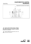
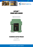
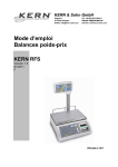
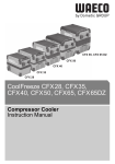
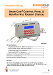
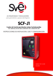
INFORMACIÓN TÉCNICA
Installation, Maintenance and User’s Manual
for Liquefied Gas Weight Control Devices
Version 5.1
LPG Técnicas en extinción de Incendios S.A.
DOC: MU/SP/01/IN
Rev: 3 Pag: 1/ 29
INFORMACIÓN TÉCNICA
CHANGE CONTROL LIST.
Page
Paragraph
Modification
LPG Técnicas en extinción de Incendios S.A.
Date
DOC: MU/SP/01/IN
Author
Rev: 3 Pag: 2/ 29
INFORMACIÓN TÉCNICA
Index
0
INTRODUCTION .............................................................................................. 5
1
GENERALITIES ............................................................................................... 6
2
DESCRIPTION ................................................................................................. 8
2.1
Central Unit ......................................................................................................................................... 8
2.2
Weight Control Unit.......................................................................................................................... 10
2.3
Weight control unit (UM) ................................................................................................................ 12
2.4
Central unit (UC) .............................................................................................................................. 12
3
INSTALLATION ............................................................................................. 14
3.1
Installation of weight control units. ................................................................................................. 15
3.2
Central unit installation.................................................................................................................... 17
4
COMMISSIONING .......................................................................................... 20
4.1
Equipment ignition: .......................................................................................................................... 20
4.2
Language selection ............................................................................................................................ 20
4.3
Address assignment: ......................................................................................................................... 21
4.4
Weight control unit programming................................................................................................... 21
4.4.1 All Weight Control Units Programming ......................................................................................... 21
4.4.2 Single Weight Control Units Programming .................................................................................... 22
4.5
Display Weight Control Unit data ................................................................................................... 24
4.6
Weight Control Unit Re-tare............................................................................................................ 24
4.7
Weight Control Unit Reset ............................................................................................................... 24
4.8
Block / Unblock System .................................................................................................................... 24
5
IN CASE OF ERROR ..................................................................................... 25
5.1
Most common problems and their solution..................................................................................... 25
5.1.1 Central Unit display and all LED on weight units are off............................................................... 25
5.1.2 Central Unit cannot find any weight control unit............................................................................ 25
5.1.3 No Weight Control Unit has green LED illuminated...................................................................... 25
LPG Técnicas en extinción de Incendios S.A.
DOC: MU/SP/01/IN
Rev: 3 Pag: 3/ 29
INFORMACIÓN TÉCNICA
5.1.4
5.1.5
5.1.6
5.1.7
Some Weight Control Units have their green LED off ................................................................... 25
Nominal charge of a cylinder is not the one anticipated ................................................................. 26
A Central Unit red LED is illuminated without intermittence. ....................................................... 26
Red LED on Weight Control Unit is illuminated without intermittent. .......................................... 26
5.2
Replacement of Central Unit fuse. ................................................................................................... 27
5.3
How to ask for support from LPG to correct abnormal conditions of system operation. .......... 27
6 ANNEX 1: INDICATIONS OF CONDITIONS IN ACCORDANCE
WITH LED .......................................................................................................... 28
7
ANNEX 2: CONDITION CODES DISPLAYED BY CENTRAL UNIT: ............ 29
LPG Técnicas en extinción de Incendios S.A.
DOC: MU/SP/01/IN
Rev: 3 Pag: 4/ 29
INFORMACIÓN TÉCNICA
Only authorised personnel and/or maintenance personnel shall
handle this equipment.
Prior to removing Central Unit bottom cap disconnect
equipment from power supply system (230 V / 110 V).
0 Introduction
This manual is addressed to installers, maintainers and users of liquefied gas weight control devices
manufactured by LPG Técnicas en Extinción de Incendios, S.A. It contains instructions for system installation,
use and maintenance.
IMPORTANT
This information is the property of LPG Técnicas en Extinción de Incendios, S.A. who claims the right to
carry out any changes without prior notice. No reproduction, modification, total or partial translation is allowed
for any purpose than internal use. Every effort has been made to ensure accuracy of information contained
herein, however, LPG disclaims any liability for the use that may be made of this information. Anyone using
the data contained in this manual does so under his own responsibility and takes whatever consequence he
may encounter.
LPG offers 1-year warranty for all equipment components. Equipment users are only authorised to handle
connectors located on charge central unit lower panel to proceed to unit connection. There are three safety
seals, two located on charge control unit and the other on central unit. Violation of these seals exempts LPG
from compliance with above mentioned warranty.
Any questions concerning information given in this manual should be addressed to:
LPG Técnicas en Extinción de Incendios, S.A.
C/ Mestre Joan Corrales, 107-109
08950, ESPLUGUES DE LLOBREGAT
Barcelona - SPAIN
Fax: + 34 93 473 74 92
Tel: + 34 93 480 29 25
e-mail [email protected]
Madrid Delegation:
LPG Técnicas en Extinción de Incendios, S.A.
C/ Sierra de Guadarrama, 32
Pol. Ind. San Fernando de Henares I
28830, SAN FERNANDO DE HENARES
Madrid - SPAIN
Fax: + 34 91 677 52 57
Tel: + 34 91 677 53 83
e-mail lpg. [email protected]
LPG Técnicas en extinción de Incendios S.A.
DOC: MU/SP/01/IN
Rev: 3 Pag: 5/ 29
INFORMACIÓN TÉCNICA
1 Generalities
Weight control devices are designed to allow continuous control of cylinder charge condition. The equipment
gives an alarm signal when there is a loss of more than 5% or 10% of initial charge, in accordance with ISO,
CEPREVEN and NFPA standards.
Systems are provided with a central unit that can be connected to the fire station as well as with several weight
control units, one for each cylinder to be controlled. Weight control units formed by a load cell which allows
detection of leakages with a resolution of 1 kg. Load cell incorporates an extensometric gage. All weight
control units are connected to central unit, by means of a BUS.
Each central unit is designed to control a maximum of 31 weight control units. More central units shall be
supplied for those installations requiring more weight control units. Each central unit has to be considered as
totally independent equipment.
Weight control devices complies with standards EN 50081-1, EN-50130-4, EN 61000-3-2 and EN 61000-3-3
for electromagnetic compatibility and CEI 60950 for electrical security. System shall be fixed on a permanent
manner on fixed supports.
The equipment described in this manual has been developed to carry out cylinder charge control. Thus
allowing to know the actual charge weight contained. Central unit consults in a continuous manner condition of
each cylinder and receives the information from weight control unit mechanically associated to it. For this
purpose each unit is assigned an internal address. Address assignment is carried out at equipment
commissioning. Those units with no address assigned, remain out of service.
This equipment allows you to check from central unit nominal charge, actual extinguishing charge, minimum
permissible weight and state of each weight control unit.
In the event of failure of power supply the equipment keeps configuration in its memory but will not carry out
weight control. The system will keep operating without any need of supervision at the moment power supply is
restored.
Note: Extreme room temperature variations may affect system performance.
LPG Técnicas en extinción de Incendios S.A.
DOC: MU/SP/01/IN
Rev: 3 Pag: 6/ 29
INFORMACIÓN TÉCNICA
Figure 1.1 Example of drawing of a cylinder bank system with weight control device
LPG Técnicas en extinción de Incendios S.A.
DOC: MU/SP/01/IN
Rev: 3 Pag: 7/ 29
INFORMACIÓN TÉCNICA
2 Description
2.1 Central Unit
4
9
5
2
1
3
13
10
8
6
7
11
12
(1) LED green:
Unit in Service: LED illuminated in a fixed manner indicates that central unit is correct and
the equipment operates accurately.
Initiation: LED in slow intermittent indicates system initiation process.
LPG Técnicas en extinción de Incendios S.A.
DOC: MU/SP/01/IN
Rev: 3 Pag: 8/ 29
INFORMACIÓN TÉCNICA
(2) LED red:
Charge leakage: Intermittent LED indicates that weight of some of the cylinders has
dropped to alarm value.
Out of service: In the event of any charge control unit being out of service, red LED will
remain illuminated in a permanent manner.
(3) Alarm Stop/Initiate Push Button:
Alarm stop: Allows to stop acoustic alarm by pressing push button lightly.
Selection: Allows system programming.
(4) Menu Push Button:
Selection: Allows system programming.
(5) Selection Push Button:
Selection: Allows system programming.
(6) Alarm relay for loss of charge: (RELE-1)
Charge leakage: Closes or opens a contact at any time a container shows a loss of charge.
(7) Feed failure relay: (RELE-2)
Power failure: In the event of system being fed by battery, closes or opens a contact
whenever voltage drops below 15 V.
(8) Out of service relay: (RELE-0)
System malfunction: Closes or opens a contact at any time a charge control unit or central
unit itself is out of service.
Note: All relays allow usually open or usually closed connection.
Attention: Relays are specified for a maximum of 24 V cc and 2A..
(9) Display
(10) Power supply
(11) Battery feeding
(12) Communication port to Charge Control Units
(13) Fuse
LPG Técnicas en extinción de Incendios S.A.
DOC: MU/SP/01/IN
Rev: 3 Pag: 9/ 29
INFORMACIÓN TÉCNICA
2.2 Weight Control Unit
1
2
3
(1) LED green:
Unit in Service: LED illuminated in a fixed manner indicates that central unit is correct and
the equipment operates accurately.
Initiation: LED in fast intermittent indicates that unit has no address assigned.
Consultation: LED in slow intermittent indicates that this unit data is being viewed by
central unit.
LPG Técnicas en extinción de Incendios S.A.
DOC: MU/SP/01/IN
Rev: 3 Pag: 10/ 29
INFORMACIÓN TÉCNICA
(2) LED red:
Low Charge: Intermittent LED indicates that cylinder weight is below alarm value.
Out of service: LED illuminated in a permanent manner indicates that unit is out of service.
(3) STOP Push Button:
Alarm stop: Allows to stop acoustic alarm by means of a light pressing.
Tare: In case of loss charge alarm by pressing more than 10 seconds it allows to re-tare
unit.
Unit initiation: By pressing more than 5 seconds process of unit address is initiated.
LPG Técnicas en extinción de Incendios S.A.
DOC: MU/SP/01/IN
Rev: 3 Pag: 11/ 29
INFORMACIÓN TÉCNICA
2.3 Weight control unit (UM)
• Maximum Weight:
200/240 kg
• Consumption:
<20 mA at rest, <25 mA alarm mode.
Inlet voltage (Vcc) of 12 V
• Dimensions:
127x150x25 mm
• Inlet / Outlet Lines:
6 lines: 2 GND (GROUND), 2 Vcc, 1 communication cell
• Push Buttons or Indicators:
1 Green LED
1 Red LED
1 Push Button
1 Acoustic Alarm
• Temperature range:
-10 to 40ºC
2.4 Central unit (UC)
• Power Supply:
Voltage:
Maximum Voltage:
• Consumption:
30 Vef (±10%) 50 or 60 Hz
110 Vef (±10%) 50 or 60 Hz
0.25 A to 230 V
0.50 A to 110 V
16 W approximately
• Battery Feeding:
Voltage:
24 Vcc
• Dimensions:
160x151x71 mm
LPG Técnicas en extinción de Incendios S.A.
DOC: MU/SP/01/IN
Rev: 3 Pag: 12/ 29
INFORMACIÓN TÉCNICA
• Input/Outlet Lines:
-
6 lines:2 GND (EARTH), 2 Vcc = 12 V (MIínim0 10 V), 2 communication
alternative feeding inlet.
battery feeding inlet.
outlet voltage communication port 12 Vcc
low charge alarm relay
feeding failure relay.
relay in service
• Push Buttons and Indicators:
1 Green LED
1 Red LED
1 Push buttons
1 Acoustic alarm
1 Display with backlight
• Temperature range:
-10 to 40ºC
• Fuse: (F1 in printed circuit)
Glass Fuse type T 20x5 with approval VDE, SEV, SEMKO, UL or CSA.
230 V
110 V
0.25 A
0.50 A
LPG Técnicas en extinción de Incendios S.A.
DOC: MU/SP/01/IN
Rev: 3 Pag: 13/ 29
INFORMACIÓN TÉCNICA
4 Installation
Refer to the appropriate Installation, Maintenance and User Manual for Fire
Extinguishing Systems to get mounting instruction of the bank of cylinders.
To carry out installation of weight control device it is necessary to have cylinder bank previously mounted
and to check the following:
• Bracket is securely fixed to the wall.
• Manifold is firmly fixed to bracket.
• Cylinders are inside bracket, on the floor and aligned with U (15) suspension vertical of 15 mm diam.
drill holes.
LPG recommends previous disconnection of all electric connections which may activate discharge of
cylinder centralized system, as well as removal of all top valve caps to avoid accidental discharge. LPG also
recommends to verify that “U” beam is placed horizontally. To proceed refer to User’s Manual supplied
with the centralized system.
LPG Técnicas en extinción de Incendios S.A.
DOC: MU/SP/01/IN
Rev: 3 Pag: 14/ 29
INFORMACIÓN TÉCNICA
3.1 Installation of weight control units.
Don’t force Weight Control Units. They can be irreversibly deformed. In case of
overload Weight Control Unit will emit an intermittent acoustic alarm.
The following procedure shall be adopted for each weight control unit:
1. Unscrew fork (10) lower fixing nuts (11) and insert fork into flange drill holes. Then, place the
removed nuts (11) and level the fork by means of turning nuts anticlockwise.
2. Assemble the hinge (9) on the fork (10).
LPG Técnicas en extinción de Incendios S.A.
DOC: MU/SP/01/IN
Rev: 3 Pag: 15/ 29
INFORMACIÓN TÉCNICA
3. Screw down the grip nut (6) in the upper part of the axle (3).
4. Place the load unit on the "U" beam (16), ensuring that the face with the LPG logotype is visible and
that the hole through which the axle (3) should pass is on the vertical of the cylinder.
5. Check that the holes for fixing the unit coincide with the holes on the beam (16).
6. To fix the unit to the beam, assemble the screw (12) with the washers (13 and 14) and the nut (15).
7. Pass the axle (3) through the free hole of the load unit (on the vertical of the cylinder).
8. Assemble the nut (8) and the hinge (9) on the axle (3).
9. Assemble the washer and turret (7) at the free end of the axle (3) and screw by hand until it reaches
the load cell.
10. Check that the axle (3) is centred in the hole of the beam without touching its sides.
11. Tighten the nut firmly (15). Press the turret (7) until the cylinder is raised about 1 centimetre from the
floor.
12. Check that the cylinder is not resting on any surface or swinging.
Once all weight control units have been mounted connect them through the telephone cable (14). Two
connectors shall remain free located at start and end of the line.
LPG Técnicas en extinción de Incendios S.A.
DOC: MU/SP/01/IN
Rev: 3 Pag: 16/ 29
INFORMACIÓN TÉCNICA
3.2 Central unit installation
Attention:
Only authorised personnel and/or maintenance personnel shall handle this
equipment.
Prior to removing Central Unit bottom cap disconnect equipment from power
supply system (230 V / 110 V).
Note: Electrical connection shall be performed with no power supply on line.
1. Place unit on wall or support.
2. Remove lower cap.
Earth Connection
Power Supply
3.
Communication
Relay
Perform power supply connection.
Perform a permanent connection through indicated orifice with a fixed tube of 16 mm inner diameter.
Earth connection should be connected. Incorporate a disconnection device of easy access. In this
case a disconnection device shall have a contact separation of at least 3 mm and shall be able to
disconnect both poles.
Attention: Use cable type H03 VV-F o H03 VVH2-F.
LPG Técnicas en extinción de Incendios S.A.
DOC: MU/SP/01/IN
Rev: 3 Pag: 17/ 29
INFORMACIÓN TÉCNICA
4.
Perform Central Unit earth connection to bracket in accordance with sketch and to screw indicated in the
sketch using a Glover or grooved washer.
Attention: Cable used for earth connection shall be type
H03 VV-F or H03 VVH2-F.
4. If necessary perform battery connection.
5. Perform communication electrical connection in accordance with sketch if needed (refer to position 12
at chapter 2.1):
Yellow/Blue
Orange/Green
Red
Black
RJ11 Connector
Blue
Yellow
Green
Red
Black
Orange
Note: Color of cable supplied may change. It’s important to keep same correspondence..
In the event of performing a connection of more than 16 measurement units, two parallel lines should be
installed and should be connected to Central Unit communication port. Each line should have a maximum
of 16 units in series. For further information contact LPG.
LPG Técnicas en extinción de Incendios S.A.
DOC: MU/SP/01/IN
Rev: 3 Pag: 18/ 29
INFORMACIÓN TÉCNICA
6. Perform relay connection.
7. Connect nearest weight unit free connector to central unit. Maximum distance between Central Unit
and nearest Weight Control Unit cannot exceed 7 m. For further information contact LPG.
8. Replace lower cap.
LPG Técnicas en extinción de Incendios S.A.
DOC: MU/SP/01/IN
Rev: 3 Pag: 19/ 29
INFORMACIÓN TÉCNICA
4 Commissioning
All operations described in this chapter are to be carried out for equipment to be operative. If operations are
not completed there will be operating problems. Whenever a number of weight control units is added
addresses shall be assigned to all weight control units.
In the event of an error being detected during commissioning process refer to chapter “5. In case of error”.
4.1 Equipment ignition:
1. Check that all weight control units are interconnected by means of telephone cable and that central unit is
connected to nearest unit.
2. Connect central unit to power supply. Verify through display that internal test is being carried out.
3. Verify that SISTEMA O.K. appears on display.
ATTENTION: Central Units are supplied in Spanish language. To change to English:
1. Press Menu Button or Selection Button until SISTEMA O.K. appear on display.
2. Press Selection Button until IDIOMA appears on display. Press Start/Alarm Stop
Button.
3. Press Selection Button until English appears on display. Press Start/Alarm Stop
Button.
4. Press Selection Button until SYSTEM O.K. appear on display.
SYSTEM O.K. is considered the starting point for all operations described in this manual:
• From SYSTEM O.K. window, Menu Button will allow to select which unit is displayed. Every time that
Menu Button is pressed next unit is displayed until SYSTEM O.K. window is reached again.
• From SYSTEM O.K. window, Selection Button will allow to program system, initialize units and
program units. To move from one option to the other Selection Button has to be pressed until SYSTEM
O.K. window is reached again. To select any option press Start/Alarm Stop Button.
• To go to SYSTEM O.K. window from any point press at the same time Menu Button and Selection
Button.
4.2 Language selection
1. From SYSTEM O.K. window press Selection Button until LANGUAGE appears on display. Press
Start/Alarm Stop Button.
LPG Técnicas en extinción de Incendios S.A.
DOC: MU/SP/01/IN
Rev: 3 Pag: 20/ 29
INFORMACIÓN TÉCNICA
2. Press Selection Button until desired language appears on display. Press Start/Alarm Stop Button.
4.3 Address assignment:
This operation has to be done before units can be programmed in order to Central unit to recognize each
weight control unit installed. This operation can be done any time without modifying other data and has to be
done every time that a new weight control unit is installed.
1. From SYSTEM O.K. window press Selection Button until SET ADDRESS appears on display.
Press Start/Alarm Stop Button until acoustic signal is heard and display shows the following information:
SYSTEM INIT
Wait-Found: 0
2. Check that central unit green LED flickers.
3. Check that all weight control units green LED flickers thus indicating initiating process. Weight control unit
red LED remain illuminated in a fixed manner. If there are any weight control unit with green LED not
flicking go to point 5 and re-start process.
4. Press STOP button on each weight control unit until a brief acoustic signal is heard. Check that green
LED is illuminated in a fixed manner. This operation shall not be carried out with more than one unit
simultaneously.
5. Press Alarm Stop/ Initiating Button on central unit to finish address assignment process.
4.4 Weight control unit programming
ATTENTION: Following steps shall be carried out with all cylinder banks prior to proceeding. Check
that all cylinder hoses are perfectly installed.
To prevent hose resistance from having a repercussion on system weight readings and producing deviation
after system goes into service, it is recommended to allow for a period of 24 hours prior to continue process.
Thereafter, flexible hoses will have adapted to their definite position and will not cause stress on weight units.
Weight control units can be programmed any time. When a Weight control unit is programmed Central unit
informs Weight Control unit with the Nominal charge weight of cylinder attach to it and the maximum
percentage allowed to leak.
4.4.1
All Weight Control Units Programming
1. From SYSTEM O.K. window press Selection Button until PROGRAM UNITS appears on display.
Press Start/Alarm Stop Button.
2. Press Selection Button until ALL UNITS appears on display. Press Start/Alarm Stop Button.
Nominal cylinder charge selection
Value programmed at this point is the extinguishing agent mass that each cylinder of the system has.
LPG Técnicas en extinción de Incendios S.A.
DOC: MU/SP/01/IN
Rev: 3 Pag: 21/ 29
INFORMACIÓN TÉCNICA
3. Nominal weight programmed will be displayed. Cursor flashing is positioned at hundreds position:
_ 0 kg
If Menu Button is selected hundred value will increase. If Selection Button is pressed hundred value will
decrease.
4. Press Start/Alarm Stop Button to confirm hundred value. Cursor flashing will move to tens position:
_0 kg
If Menu Button is selected ten value will increase. If Selection Button is pressed ten value will decrease.
5. Press Start/Alarm Stop Button to confirm tens value. Cursor flashing will move to units position:
0 kg
If Menu Button is selected unit value will increase. If Selection Button is pressed unit value will decrease.
6. Press Start/Alarm Stop Button to confirm.
Alarm Threshold selection
7. Press Selection Button until maximum percentage of extinguishing agent mass lost allowed (5% or 10%)
appears on display. Press Start/Alarm Stop Button.
8. At this point Central unit will program Nominal weight and alarm threshold to all weight control units
connected to it. Check that all weight control unit shows green LED on and red LED off.
Note: Due to system precision in case that 10% is selected as Threshold, Nominal Charge has to be
greater than 15 kg. If 5% is selected as Threshold, Nominal Charge has to be greater than 30 kg.
4.4.2
Single Weight Control Units Programming
Following operation shall be carried if it’s necessary to be programmed independently . It works basically as
4.4.1. All Weight Control Unit Programming but allows user to specify Actual Weight inside cylinder.
1. From SYSTEM O.K. window press Selection Button until PROGRAM UNITS appears on display.
Press Start/Alarm Stop Button.
2. Press Selection Button until SINGLE UNIT appears on display. Press Start/Alarm Stop Button.
3. UNIT: 0 will be displayed. Use Menu and Selection buttons to select unit to be programmed. To
cancel select 0 value. Press Start/Alarm Stop Button.
Nominal cylinder charge selection
Value programmed at this point is the extinguishing agent mass that cylinder of the system has. Refer to 4.4.1.
All Weight Control Units Programming.
LPG Técnicas en extinción de Incendios S.A.
DOC: MU/SP/01/IN
Rev: 3 Pag: 22/ 29
INFORMACIÓN TÉCNICA
Alarm Threshold selection
Value programmed at this point is the maximum percentage of extinguishing agent mass lost allowed (5% or
10%). Refer to 4.4.1. All Weight Control Units Programming.
Actual cylinder charge selection
Value programmed at this point is the real content of extinguishing agent mass that cylinder of the system has.
Follow same procedure as Nominal cylinder charge selection.
LPG Técnicas en extinción de Incendios S.A.
DOC: MU/SP/01/IN
Rev: 3 Pag: 23/ 29
INFORMACIÓN TÉCNICA
4.5 Display Weight Control Unit data
From SYSTEM O.K. window press press Menu Button to display units. To check the following data for
each weight control unit, use Selection Button:
-
Device Nº: A number from 1 to 31
Nom. W.: Nominal extinguishing charge inside cylinder programmed.
Act. W.: Extinguishing charge inside cylinder.
Al. lim.: Value of minimum extinguishing charge allowed.
State: “0x0”
Check that green LED on each weight control unit flickers in slow sequence when checked/ consulted from
central unit.
NOTE: If Nominal Weight to be programmed is greater than weight measured, Weight Control Unit will
use measured weight as Actual Weight and Tare Error will be displayed (State: “0x4”)
4.6 Weight Control Unit Re-tare
In case that a weight control unit has detect lost of charge below minimum allowed value systems allows to retare unit. To do so press STOP button on Weight Control Unit during 10 seconds until an acoustic signal is
heard. Nominal weight will be kept the same as before and new minimum allowed charge will be calculated.
Minimum allowed charge will be the Actual Extinguishing Weight in cylinder minus the Alarm Threshold
programmed.
4.7 Weight Control Unit Reset
To reset a Weight Control unit to inoperative state (0x5) place cylinder back to the ground and remove all
weights from Weight Control Unit. Press STOP button on Weight Control Unit until an acoustic signal is heard.
Check state on Central unit display to confirm.
Note: Reset Weight Control Unit is recommended after a system discharge to avoid continuos weight loss
alarm condition.
4.8 Block / Unblock System
In case of pressing Menu Button and Init Button at the same time system will be block. When system is
blocked Programming, Consulting, … operations will be disabled. This will not impare proper function of the
system (weight control).
“*” will be shown on display when system is blocked.
To Unblock press both buttons again.
LPG Técnicas en extinción de Incendios S.A.
DOC: MU/SP/01/IN
Rev: 3 Pag: 24/ 29
INFORMACIÓN TÉCNICA
5 In case of error
This chapter describes verifications to be carried out by maintenance competent personnel in case of
equipment malfunction and corrective actions to be taken..
This chapter is divided into the following subchapters:
1. Most common problems and their solution.
2. Central Unit fuse replacement.
3. How to ask technical support to LPG for system operation abnormal conditions.
Refer to Annex to obtain information on meaning of LED, messages and condition codes which central unit
displays.
ANNEX 1: Indications of Condition in accordance with LED
ANNEX 2: Condition Codes displayed on Central Unit.
5.1 Most common problems and their solution.
5.1.1
Central Unit display and all LED on weight units are off
1. Check that equipment is connected to power supply system (electric power, batteries or both).
2. If supply is only by means of electric power system, check Central Unit internal fuse (see item 6.2).
3. If problems doesn’t solve contact LPG.
5.1.2
Central Unit cannot find any weight control unit
1. Check that Weight Control Units are connected to BUS and their green LED illuminated.
2. Check that connection order of BUS wire is accurate (see item 6 section 3.2) .
5.1.3
No Weight Control Unit has green LED illuminated.
1. Check that Central Unit connection order of BUS wire is accurate (see item 6 section 3.2) .
2. Connect Central Unit BUS directly to a Weight Control Unit different to the one it was previously
connected to.
5.1.4
-
If that unit green LED illuminates, then Weight Control Unit which was previously connected to
same does not operate properly.
-
If this unit green LED is off, check if between GND (Ground) lines and + central unit 12V there is
a higher voltage than 10 Volts. If voltage is lower than 10 Volts, Central Unit has broken down.
Some Weight Control Units have their green LED off
1. Check that Weight Control Unit is connected to BUS and that the cable has not been damaged-.
2. Exchange cable with the other unit that works:
LPG Técnicas en extinción de Incendios S.A.
DOC: MU/SP/01/IN
Rev: 3 Pag: 25/ 29
INFORMACIÓN TÉCNICA
- If LED remains off contact LPG.
NOTE: To ensure that a Weight Control Unit does not operate properly, the best choice is to connect it directly
to Central Unit using the same cable used with a Weight Control Unit that works (Keep all other Weight
Control Units disconnected)-.
5.1.5
Nominal charge of a cylinder is not the one anticipated
1. Follow Single Unit Programming steps.
2. If problems doesn’t solve contact LPG.
5.1.6
A Central Unit red LED is illuminated without intermittence.
Indicates that some Weight Control Units are out of service.
Select from the menu the different cylinders and check their state (annex 2):
1x__ There is a a communication failure. Check that all connections are performed and cables are in
good conditions.
0x01 Low cylinder charge.
0x02 Overload. Check that weight unit has not been overcharged. If proble persist contact LPG.
0x03 Internal Weight Control Unit error. Contact LPG.
0x04 Tare error. Real Weight is less than Nominal Weight. Check that Nominal Weight is not higher than
Real Weight. Repeat cylinder programming process as described in chapter 4.
0x05 Weight Control Unit is not programmed.
5.1.7
Red LED on Weight Control Unit is illuminated without intermittent.
1. If it has not been programmed yet, it is the correct situation. LED will go off when programmed.
2. If it has been programmed already and it has been accurate (check weight control unit data from
Central Unit display)it indicates that Weight Control Unit does not operate well.
LPG Técnicas en extinción de Incendios S.A.
DOC: MU/SP/01/IN
Rev: 3 Pag: 26/ 29
INFORMACIÓN TÉCNICA
5.2 Replacement of Central Unit fuse.
Only authorised personnel and/or maintenance personnel shall handle this equipment.
Prior to removing Central Unit bottom cap disconnect equipment from supply system
(230 V / 110 V).
If battery feeding works but power supply does not, probably feed fuse is open. To replace it proceed as
follows:
1.
2.
3.
4.
5.
6.
Disconnect equipment from power supply.
Remove lower cap.
Remove fuse from fuse holder (F1 in printed circuit)
Replace fuse in accordance with specifications in item 2.4.
Close box.
Connect equipment to power supply.
5.3 How to ask for support from LPG to correct abnormal conditions of system
operation.
1. Take note of tests carried out in this guide and their results.
2. Contact LPG:
LPG Técnicas en Extinción de Incendios, S.A.
C/ Mestre Joan Corrales, 107-109
08950, ESPLUGUES DE LLOBREGAT
Barcelona - SPAIN
Fax: + 34 93 473 74 92
Tel: + 34 93 480 29 25
e-mail [email protected]
Madrid Delegation:
LPG Técnicas en Extinción de Incendios, S.A.
C/ Sierra de Guadarrama, 32
Pol. Ind. San Fernando de Henares I
28830, SAN FERNANDO DE HENARES
Madrid - SPAIN
Fax: + 34 91 677 52 57
Tel: + 34 91 677 53 83
e-mail lpg. [email protected]
LPG Técnicas en extinción de Incendios S.A.
DOC: MU/SP/01/IN
Rev: 3 Pag: 27/ 29
INFORMACIÓN TÉCNICA
6
ANNEX 1: Indications of Conditions in accordance with LED
CENTRAL UNIT
GREEN LED
Off
Fixed illumination
Fixed illumination
Fixed illumination
Fixed illumination
Off
Intermittent
illumination
RED LED
BUZZER
CONDITION
Off
Off
Intermittent
Intermittent
Fixed illumination
Fixed illumination
Off
Silence
Silence
Activated
Silence
Silence
Activated
Silence
unit not fed
unit in operation
alarm low charge not recognised
alarm low charge recognised
some weightcontrol units out of service
Equipment fatal error
Initiating mode
Low charge not recognised is defined as the moment when loss of charge is detected until a person presses
Alarm Stop Push Button. At this moment there is a loss of charge and somebody has been informed about it.
WEIGHT CONTROL UNIT
GREEN LED
RED LED
BUZZER
CONDITION
NORMAL OPERATION
Off
Off
Silence
unit not fed
Fixed illumination
Off
Silence
unit in operation
Fixed illumination
Intermittent
Activated
alarm low charge not recognised 1
Fixed illumination
Intermittent
Silence
alarm low charge recognised
Fixed illumination
Fixed Illumination
Silence
inoperative unit
Fast intermittent
unit with no address assigned
Low intermittent
unit consulted by central unit
OPERATION IN ADDRESS ASSIGNMENT PROCESS
Intermittent
Fixed Illumination
Silence
unit not initiated
Fixed Illumination
Fixed Illumination
Silence
initiated unit
1 Low charge not recognised indicates that the key to cancel buzzer whistle has not been pressed yet.
LPG Técnicas en extinción de Incendios S.A.
DOC: MU/SP/01/IN
Rev: 3 Pag: 28/ 29
INFORMACIÓN TÉCNICA
7 ANNEX 2: Condition codes displayed by Central Unit:
CÓDE
DESCRIPTION
0x00
0x01
0x02
0x03
0x04
0x05
1x00
1x01
1x02
1x03
1x04
1x05
Weight Control Unit in perfect condition
Low Charge
Error in analogical side of Weight Control Unit / Overload
Error in bus I2C of Weight Control Unit
Tare Error
Inoperative Weight Control Unit
Communication Error1. Weight Control Unit in perfect condition
Communication Error1. Low Charge
Communication Error1. Error in analogical side of Weight Control Unit / Overload
Communication Error1. Error in bus I2C of Weight Control Unit
Communication Error1.Tare Error
Communication Error1. Inoperative Weight Control Unit
Condition codes with 1X.. indicate that communication with Weight Control Unit is not possible. In such a case,
condition code pertains to last value transmitted by Weight Control Unit in an accurate manner.
1
LPG Técnicas en extinción de Incendios S.A.
DOC: MU/SP/01/IN
Rev: 3 Pag: 29/ 29