1
7
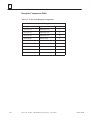
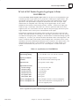
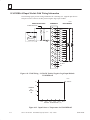
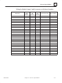
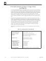
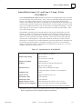
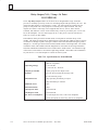
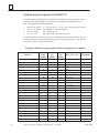
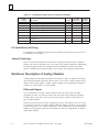
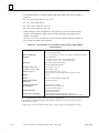
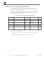
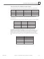
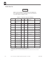
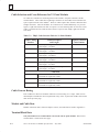
Table 7-16. Load Current Limitations for IC693MDL930
Operating
Voltage
24 to 120 VAC
24 to 120 VAC
24 to 120 VAC
240 VAC
240 VAC
240 VAC
24 VDC
24 VDC
24 VDC
24 VDC
125 VDC
Maximum Current for Load Type
Resistive
Lamp or Solenoid 4 amps
1 amp
.1 amps
4 amps
.1 amps
1 amp
4 amps
1 amp
.1 amps
.2 amps
Typical Contact Life
(number of Operations)
2 amps
.5 amps
.05 amps
2 amps
.05 amps
.5 amps
3 amps
2 amps
.5 amps
.05 amps
.1 amps
150,000
500,000
1,000,000
50,000
500,000
200,000
50,000
100,000
500,000
1,000,000
300,000
Assumes a 7 ms time constant
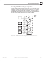
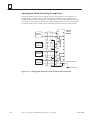
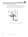
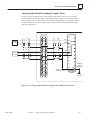
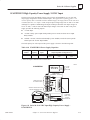
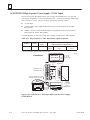
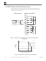
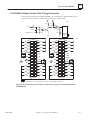
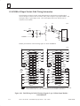
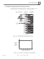
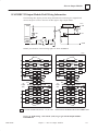
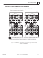
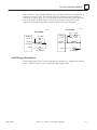
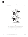
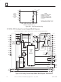
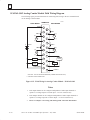
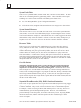
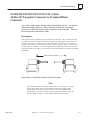
Relay contact life, when switching inductive loads, will approach resistive load contact life if
suppression circuits are used. The following figures are examples of typical suppression
circuits for AC and DC loads. The 1A, 200V diode shown in the DC load typical suppression
example is an industry standard 1N4935. The resistor and capacitor shown for AC load
suppression are standard components, available from most electronics distributors.
AC LOADS
a45151A
IC693MDL930
DC LOADS
1A, 200V
Output
Module
2
Î
Î
IC693MDL930
.022
100 Ω
Output
Module
600V
1/2W
2
Load Coil
3
3
DC SUPPLY
a45152A
Load Coil
~
AC SOURCE
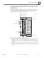
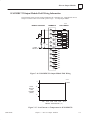
Figure 7-30. Load Suppression Examples for IC693MDL930 Output Module
7-32
Series 90-30 PLC I/O Module Specifications – July 2000
GFK-0898F