1
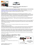
Instruction Manual for the Data Recorder Thermocouple Expander
Document Version 1.3
Model # EGT-01, TC-01
Thank you for your purchase! This instruction manual will guide you through the installation and operation of your Dual Channel Thermocouple
Expander. Please read the entire manual carefully before proceeding. If, after you read the manual, you have further questions or problems, see the
Support page on http://www.eagletreesystems.com for additional information, or email us at [email protected].
Supported Products
The Thermocouple Expander is compatible with the Eagle Tree Systems Flight Data Recorder Pro, V2, Glide, Car Data Recorders and Boat Data Recorders. It is not
compatible with our Flight Data Recorder V1.
If you have purchased a Secondary or Tertiary Thermocouple Expander, allowing up to 6 channels of Temperature to be used simultaneously, please refer to the
Secondary Expander instructions for additional information, after reading the instructions below.
Packing List
Your package should include the following: Thermocouple Expander, a printed version of this manual, and either:
a) one EGT probe with 24” leads, one 1/8” NPT probe compression fitting (top, bottom and ferrule), or
b) one CHT probe kit with rings for #8 glow plugs, and 10mm spark plugs.
Please check our website for updates to this manual which may be included if changes were made after printing.
How the Thermocouple Expander Works
The Thermocouple Expander works with your Data Recorder to measure up to two channels of thermocouple temperature. It uses a K type Thermocouple mounted in
the exhaust stream, or the cylinder head, for this purpose. Since two channels are supported, one channel can be used for EGT, and the other for Cylinder Head
Temperature. Check our website for additional probes.
Assembling and Installing the CHT Ring Probe in your Model
(Skip this section if you are not installing the CHT ring probe)
First, ensure the inner diameter of one of the two included rings is just slightly bigger than the outer
diameter of your plug. If the correct sized ring is not included in your kit, your local auto parts or
hardware store probably has one that will fit, or email us at [email protected].
Crimp the correctly fitting ring onto the brazed end of the thermocouple wire, so that the bare wire makes
good contact with the crimp area of the ring. If clearance is tight around your plug (common with glow
plug engines), the ring can be bent at right angles with the crimp with a pair of pliers – cover the ring with
a cloth when bending so that the ring will not be scratched. See the figure at right.
Once crimped, the ring is ready to be bolted under your plug. Normally, the ring will take the place of
your plug washer, if it appears to be approximately the same thickness.
Installing the EGT Sensor Probe in your Model
(Skip this section if you are not installing our EGT probe)
Permanent installation of the EGT probe involves drilling a hole to accommodate the compression fitting, possibly tapping threads in the hole, and inserting the probe
into the fitting. If this seems daunting or impractical, it may be possible for you to temporarily insert the probe through the exhaust pipe so that the tip of the probe is
close to the manifold. In this configuration probe will get oily and dirty which may shorten its life, readings may vary, and this has not been tested. If you do this
make sure also that the probe cannot enter the manifold and get caught in the piston!!! Alternative mountings may also be possible. If you have access to a K type
thermocouple probe with a mounting arrangement that you like better, it should work fine with the expander.
The following instructions pertain to permanent mounting of the probe. WARNING: Holes are forever! Take your time to plan your installation, and if possible
practice on a scrap piece of metal! To install the EGT probe, first determine where you will drill your hole. The best place for temperature readings is usually in
the muffler/exhaust pipe, as close to the exhaust manifold as feasible. The NPT fitting and the top of the probe will stick up between ½” to 1” above the mounting
surface, so make sure you have clearance above these.
First determine how you will create the hole for the NPT fitting. If the surface you are installing the fitting into is made of very soft, thin metal (such as aluminum) you
may not need a pipe tap. If the surface is thicker or harder, a pipe tap is required. If you are not sure, try to practice installation on a throwaway version of the same
material. To install without a pipe tap, first remove the muffler from the engine to avoid metal fragment contamination. Mark the center of your hole location with
Copyright © 2003 Eagle Tree Systems, LLC
http://www.eagletreesystems.com
Page 2
a punch or other sharp object, and drill a 3/8” hole straight down through the surface. A drill press with clamps makes this a bit easier. Make sure that you don’t drill
in too far after penetrating the wall of the pipe. See Figure 1.
If you are using a 1/8” NPT tapered pipe tap (available at your hardware store), follow the instructions with the tap. Typically a 5/16” hole is drilled straight down,
then insert the pipe tap is used to cut the threads. IMPORTANT: The pipe tap is tapered, so you want to only want to turn the tap until the bottom threads of the tap are
only slightly deeper than flush with the inside of the exhaust pipe wall. If you tap in too far, your fitting will be have to screwed in very deeply.
Now that you have either drilled or tapped your hole, install the engine side of the fitting by tightening the tapered thread end into the hole (Figure 2). Ideally the tip of
the fitting would be flush with the inside of the exhaust flow path, and not much deeper. However, if your pipe wall is thin, you may need to go deeper.
Tighten the
fitting so that it is securely mounted, but don’t over tighten to avoid damaging the muffler/exhaust. Once this step is complete, thoroughly clean the muffler and
fitting to remove any metal shavings, then reinstall on the engine.
To install the probe in the fitting, slide the top part of the fitting over the probe with the threads facing outward, and then slide the small brass ferrule (you didn’t lose it,
did you?) onto the probe. Then hand screw the assembly into the bottom part of the fitting. The probe should be adjusted so that the tip is approximately centered in
the exhaust gas stream. Tighten the top nut of the fitting just tight enough to keep the probe firmly mounted (Figure 3).
The last step is to attach the wires of the probe to the Thermocouple Expander board. The probe wires are attached to the board via a screw terminal block. Just loosen
the center screw and the screw nearest the top edge of the board (for probe 1), insert the red wire in the center hole, and the yellow wire in the top hole, and tighten. If
you are installing two probes, the red wire of each is placed in the center hole. If desired, the wire can be cut to shorten it. Use heatshrink on the ends of the each
wire to keep the insulation from unbraiding if you decide to cut it.
Figure 1
Figure 2
Figure 3
Connecting the Thermocouple Expander to the Recorder
The expander plugs into your Data Recorder as shown in Figure 1. Make sure that you connect it in
the correct location on the recorder, and with the correct polarity! Connect the Thermocouple
Expander to your Recorder.
Logging Data with the Thermocouple Expander
Data from both Thermocouple channels can be logged by clicking “Tools, Parameters To Log in the
Recorder”, and selecting the “Thermocouple Temperature A” and/or “Thermocouple Temperature
B.”
If you have purchased a Secondary Thermocouple Expander, see the additional instructions that
should have been included with your Secondary Expander.
Visualizing Data with the Thermocouple Expander
Choosing “Tools, Choose Instruments to Display on PC Screen” and checking one or more of the following lets you see recorded or live mode data in the app:
•
Thermocouple Meter A
•
Thermocouple Meter B
•
Thermocouple A Numeric
•
Thermocouple B Numeric
To see a graph of the data, click on “Graph Data!” and “Thermocouple A” and “Thermocouple B” graph options will appear in the graphing options for the Y axes.
To see the file with Excel or other viewer, save the file as usual, and the file header will have “Thermocouple A” and “Thermocouple B” columns.
If you have purchased a Secondary Thermocouple Expander, see the additional instructions that should have been included with your Secondary Expander.
If you have the Seagull Wireless option, the Thermocouple Expander channels can also be configured for the LCD Display. See the Seagull users manual for
instructions on configuring parameters with the LCD Display.
Copyright © 2003 Eagle Tree Systems, LLC
http://www.eagletreesystems.com
Page 3
Troubleshooting
Below is a list of problems that may be encountered, and steps to remedy them. If your particular issue is not addressed by the below, see the Support page on
http://eagletreesystems.com or email [email protected]. Include a full description of your problem, your machine configuration, brands/models of receivers,
transmitters and servos, application and Recorder firmware version if possible (from Help->About in the app) and any other relevant details.
Issue: I do not see Thermocouple temperature logged in the Recorder.
Solution:
•
Make sure that you have selected logging of “Thermocouple Termperature” or “Exhaust Gas Temperature” in the “Choose What to Log” dialog box under
the Tools menu.
•
Ensure that you have selected Thermocouple Temperature in the “Choose What to Display” dialog box under the Tools menu.
•
Doublecheck your connections to ensure that the Recorder is connected correctly to the Thermocouple Expander, and the battery.
•
Make sure the temperature probe is correctly attached to the Thermocouple Expander.
•
Ensure that you are operating within the ranges listed in the Specifications section below.
Issue: I do not believe that the temperature is reading temperature correctly.
Solution: Test the temperature probe with a known temperature value, such as boiling water. If it does not read correctly, email us.
Thermocouple Expander Specifications
Channels: Dual
Max Temperature: 2000+ degrees F. Software will calibrate to around 1800 degrees C, but this has not been tested.
Weight: approximately 0.8 ounces with Expander board, probe and fitting.
Limited Warranty
Eagle Tree Systems, LLC, warrants the Thermocouple Expander to be free from defects in materials and workmanship for a period of one (1) year from the date of
original purchase. This warranty is nontransferable. If your unit requires warranty service during this period, we will replace or repair it at our option. Shipping cost
to us is your responsibility. To obtain warranty service, contact us by phone, fax or email to request an RMA number. No returns will be accepted without this number.
This limited warranty does not cover:
•
•
The Software included with the Data Recorder. See the Software license agreement for more information on Software restrictions.
Problems that result from:
o External causes such as accident, abuse, misuse, or problems with electrical power
o Servicing not authorized by us
o Usage that is not in accordance with product instructions
o Failure to follow the product instructions
THIS WARRANTY GIVES YOU SPECIFIC LEGAL RIGHTS, AND YOU MAY ALSO HAVE OTHER RIGHTS WHICH VARY FROM STATE TO STATE (OR
JURISDICTION TO JURISDICTION). OUR RESPONSIBILITY FOR MALFUNCITONS AND DEFECTS IN HARDWARE IS LIMITED TO REPAIR AND
REPLACEMENT AS SET FORTH IN THIS WARRANTY STATEMENT. ALL EXPRESS AND IMPLIED WARRANTIES FOR THE PRODUCT, INCLUDING,
BUT NOT LIMITED TO, ANY IMPLIED WARRANTIES AND CONDITIONS OF MERCHANTABILITY AND FITNESS FOR A PARTICULAR PURPOSE,
ARE LIMITED IN TIME TO THE TERM OF THE LIMITED WARRANTY PERIOD AS DESCRIBED ABOVE. NO WARRANTIES, WHETHER EXPRESS OR
IMPLIED, WILL APPLY AFTER THE LIMITED WARRANTY PERIOD HAS EXPIRED. SOME STATES DO NOT ALLOW LIMITATIONS ON HOW LONG
AN IMPLIED WARRANTY LASTS, SO THIS LIMITATION MAY NOT APPLY TO YOU.
WE DO NOT ACCEPT LIABILITY BEYOND THE REMEDIES PROVIDED FOR IN THIS LIMITED WARRANTY OR FOR CONSEQUENTIAL OR
INCIDENTAL DAMAGES, INCLUDING, WITHOUT LIMITATION, ANY LIABILTY FOR THIRD-PARTY CLAIMS AGAINST YOU FOR DAMAGES, FOR
PRODUCTS NOT BEING AVAILABLE FOR USE, OR FOR LOST DATA OR LOST SOFTWARE. OUR LIABILITY WILL BE NO MORE THAN THE
AMOUNT YOU PAID FOR THE PRODUCT THAT IS THE SUBJECT OF A CLAIM. THIS IS THE MAXIMUM AMOUNT FOR WHICH WE ARE
RESPONSIBLE.
SOME STATES DO NOT ALLOW THE EXCLUSION OR LIMITATION OF INCIDENTAL OR CONSEQUENTIAL DAMAGES, SO THE ABOVE LIMITATION
OR EXCLUSION MAY NOT APPLY TO YOU.
Eagle Tree Systems, LLC
http://www.eagletreesystems.com
[email protected]
Service/Support: 425-614-0450
Copyright © 2003 Eagle Tree Systems, LLC
http://www.eagletreesystems.com