1
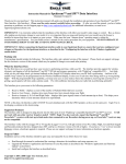
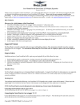
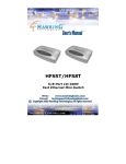
Instruction Manual for the Data Recorder Electric Expander
Document Version 3.0
Model # CDR-ECV, CDR-ECV140, CDR-ECV300
Thank you for your purchase! This instruction manual will guide you through the installation and operation of
your Data Recorder Electric Expander. Please read the entire manual carefully before proceeding. If, after you
read the manual (including the Troubleshooting section!!), you have further questions or problems, see the Support
page on http://www.eagletreesystems.com for additional information, or email us at
[email protected].
If you have purchased a Secondary or Tertiary Electric Expander, allowing up to three Electric Expanders to
be used simultaneously, please refer to the Secondary Expander instructions for additional information, after
reading the instructions below.
WARNING: High Voltages can cause electric shock. Be extremely careful when
working with high voltage packs! Work with High Voltages at your own risk!
Packing List
Your package should include the following: Electric Expander (standard 100 amp, or larger 140 amp or 300 amp sensors), and a
printed version of this manual. Please check your box for printed addenda to this manual which may be included if changes were
made after printing.
How the Electric Expander Works
The Electric Expander is compatible with our Flight Data Recorder V2/Pro, all Seagull systems, Car Data Recorder, and Boat Data
Recorder products. It is not compatible with our original Flight Data Recorder V1 product.
The Electric Expander works with your Data Recorder to
measure motor battery pack voltage and current. The
Expander measures current by means of a tiny,
lightweight hall effects current sensor ring. Battery
pack voltage is measured by the alligator clip attached to
the expander. NOTE: a common ground between your
battery pack and the Recorder is required for the voltage
measurement to work correctly.
Connecting the Electric Expander
to the Recorder
Note: If you have a Secondary or Tertiary Electric
Expander, please refer to the Secondary Expander
instructions for plugging in your Expander to the
Recorder.
Connect the polarized, 5 pin Electric Expander connector
to the recorder as shown in Figure 1a. NOTE: The plug
is a tight fit – slightly tilting the 5 pin connector back
toward the center of the Recorder can aid installation. If
Copyright © 2003-2010 Eagle Tree Systems, LLC
http://www.eagletreesystems.com
Page 2
you still have problems fitting it, you might need to lightly sand the top of the connector (nearest the red wire) with sandpaper, but this
should not be necessary.
EXTREMELY IMPORTANT: The Electric Expander Connector **MUST** be connected correctly
to your Recorder, or severe damage to the Recorder and other equipment could occur, which will void the
warranty. The Expander connects as shown in Figure 1A, to the right of the USB connector, with the RED wire of
the connector facing UP. If you are uncertain as to how to connect the expander, don’t hesitate to email us at
[email protected]!
Connecting the Electric Expander to Your Battery
To measure current the hall effects current sensor ring can be installed around either the positive or negative wire leading from your
battery to your speed controller. It works through the wire’s insulation, and hence no cutting of the wire is necessary. It can be
installed facing either direction, as it is not polarized.
The alligator clip is for measuring battery pack voltage. It should be attached to an exposed part of the positive (normally red) battery
wire or terminal between the battery and the speed controller. It must be in direct electrical contact with the positive battery wire.
Alternatively, the alligator clip can be removed and soldered to the wire leading to the ESC for a more permanent installation.
If an easily removable installation is desired, one convenient way to do this is to have a removable wire “section” with Deans or other
plugs on either end (male/female). Both the current and voltage leads of the Electric Expander can attach to this wire section (the
alligator clip is normally cut off and the voltage wire soldered), and the section can be removed easily from the model when electric
measurement is not desired.
ESCs with isolation between BEC/Throttle ground and Main Battery Ground
Note that there must be electrical conductivity between the ground wire of your main battery and the Recorder’s internal ground, for
voltage measurement to work correctly. Normally, when the Recorder is connected to your receiver via one or more of the
Recorder’s servo connections, the
ground wire of the ESC’s BEC/Throttle
output results in the correct grounding.
However, some ESCs isolate battery
ground from the ESC/BEC throttle
output ground. The easiest way to tell
if there is ground isolation is, with
everything disconnected from your
ESC, to measure the resistance between
the main battery negative input of the
ESC, and the BEC/Throttle ground
wire. If the resistance is greater than an
ohm or two, there is isolation.
In these cases, for the Recorder to
measure voltage correctly, the
recorder’s ground must be connected to
the ground of the battery to be
measured.
There are two ways to do this:
a)
RECOMMENDED: Disconnect all connections between your Receiver (including BEC/Throttle output of the ESC) and
your Recorder, and power the recorder from a separate small battery. Then, connect a small ground wire between one of the
Recorder’s servo ground pins, and the negative lead of the battery being measured, as shown in Figure 2. Note that the
resulting connections should not bypass the ESC’s isolation between the BEC/Throttle ground and the ground of the battery
being measured, since the BEC/Throttle ground is NOT connected to the recorder. Note that servo position logging will
not be possible in this scenario.
b)
If you want to continue to power the Recorder from the ESC’s BEC output or the battery you are using to power the
Receiver (and to be able to log servo positions), you will need to leave the servo connections from the Receiver to the
Copyright © 2003-2010 Eagle Tree Systems, LLC
http://www.eagletreesystems.com
Page 3
Recorder connected, AND you will need to connect the small wire between the between one of the Recorder’s servo ground
pins, and the negative lead of the battery being measured, as shown in Figure 2. CAUTION! This configuration causes
the internal ESC isolation to be bypassed. While the vast majority of the customers who have done this with our
equipment have not reported any problems, we have had one report of two different high powered ESC’s which may
have been damaged by performing this connection. Therefore, we strongly recommend contacting the ESC
manufacturer or consulting the ESC manual to ensure that connecting the ground of the ESC’s throttle output and
the main battery ground together will not cause a problem with that particular ESC, before proceeding. Bypassing
the ESC isolation is done at your own risk!
If your ESC has isolation, and you don’t understand how to set up the recorder in this configuration, don’t hesitate to visit the
“Support” page of our website for information about how to contact us with your issue.
Configuring the Expander with the Recorder and the Application
If you have not already done so, install your Data Recorder in your model and set up the Recorder software as described in your
instruction manual.
Zeroing the Current Sensor for First Time Use
Some ESCs, servos, etc., can draw a large constant current when the systems are powered up. Therefore, it is good to set the zero
current reference with your new Electric Expander. To do this, simply connect the Electric Expander to your Recorder, and connect
the Recorder to USB, but make sure there is no current draw through the ring current sensor (don’t connect a battery pack to the ESC).
Then, in the Windows Application, click “Tools, Rezero current sensors” and follow the instructions on that page. Note that this only
needs to be done once, but it’s not a bad idea to do it once a year or so, to account for any slight current sensor drift over time.
Special Instructions for the High Voltage Sensor
If you ordered the High Voltage option with your Recorder, complete the following step:
• Connect the Recorder and click “Advanced, Custom Hardware Options” and click ON the option “My Recorder has the High
Voltage option.” Then, click “OK”.
Special Instructions for 140 Amp and 300 Amp Sensors
If you are using the 300 Amp Sensor, complete the following step:
• Connect the Recorder and click “Advanced, Custom Hardware Options” and click ON the option “I am using the 300 Amp
Current Sensor.” Then, click “OK”.
If you are using the 140 Amp Sensor, complete the following step:
• Connect the Recorder and click “Advanced, Custom Hardware Options” and click ON the option “I am using the 140 Amp
Current Sensor.” Then, click “OK”.
Recorder Logging Setup
If you desire to log current or voltage in the Recorder, connect the Recorder to your PC as described in the Recorder manual, and
under Tools->Choose What to Log, choose Electric Motor Voltage and Electric Motor Current in the Optional Parameters section.
Choose other parameters you want to log as described in the Recorder manual.
To display the new parameters, under Tools->Choose What to Display, choose numeric and/or instrument display of Motor Voltage,
Motor Current, Motor Wattage, and/or cumulative amp-hours.
Seagull Dashboard Setup
If you are using the Seagull Wireless system, choose “Tools, Choose Parameters to Display on the Seagull Dashboard” and select the
desired Dashboard parameters to display, per the Seagull manual.
Playing Back Data after the Run
After your race, download data to your PC as described in the Recorder Manual. If you have selected to log and display motor
voltage, current, and/or RPM, these instruments and/or numerical readouts should appear in the application.
Troubleshooting
Copyright © 2003-2010 Eagle Tree Systems, LLC
http://www.eagletreesystems.com
Page 4
Below is a list of problems that may be encountered, and steps to remedy them. If your particular issue is not addressed by the
below, see the Support page on http://eagletreesystems.com or email [email protected]. Include a full description of your
problem, your machine configuration, brands/models of receivers, transmitters and servos, application and Recorder firmware version
if possible (from Help->About in the app) and any other relevant
details.
Issue: I do not see motor voltage and/or current values changing after
using the Expander.
Solution:
• Make sure that you have selected logging of voltage and/or
current in the “Choose What to Log” dialog box under the
Tools menu.
• If voltage measurement is not working, but current is working,
see the “ESC’s with isolation between BEC/Throttle ground
and Main Battery Ground” section above.
• If Current is not working correctly, please verify that the Ring
sensor is correctly installed on the Electric Expander harness.
Please see the figure below.
• Ensure that you have selected motor voltage and/or current in the “Choose What to Display” dialog box under the Tools
menu.
• Double check your connections to ensure that the Recorder is connected correctly to the Electric Expander, and the battery.
• Ensure that you are operating within the ranges listed in the Specifications section below.
Issue: My Electric Expander seems to be out of calibration. The readings I receive for current and/or voltage are somewhat incorrect
or differ slightly from my favorite meter.
Solutions:
• If you have a “High Voltage” recorder, or a “High Current” (140 or 300 amp) Electric Expander, ensure you have made the
“Custom Hardware Options” settings as described above.
• If the current sensor appears to be reading incorrectly, make sure you’ve performed the steps in the “Zeroing the Current
Sensor for First Time Use” section above.
• ADVANCED: If current and/or voltage seem to be reading slightly incorrectly, or you wish to calibrate the readings to a
particular meter you use, click “Tools, Calibrate Pack Voltage and Amperage Readings” in the windows application, and
follow the instructions.
Electric Expander Specifications
Motor Voltage: 0 to 50V (70 volts with High Voltage recorder option)
Motor Current: (standard sensor) 0 to 100 amps, with approximately 50 mA resolution
(140 amp sensor) 0 to 140 amps, with approximately 70 mA resolution
(300 amp sensor) 0 to 300 amps, with approximately 150 mA resolution
Weight: (standard sensor and 140 amp sensor) approximately 0.3 ounces
(300 amp sensor) approximately 1 ounce
Inside Diameter of Sensor Ring:
100 amps: ~5mm
140 amps: ~7mm
300 amps: ~22 mm
Limited Warranty
Eagle Tree Systems, LLC, warrants the Electric Expander to be free from defects in materials and workmanship
for a period of one (1) year from the date of original purchase. This warranty is nontransferable. If your unit
requires warranty service during this period, we will replace or repair it at our option. Shipping cost to us is
your responsibility.
To obtain warranty service, contact us by phone, fax or email to request an RMA number. No returns will be accepted without this
number.
This limited warranty does not cover:
Copyright © 2003-2010 Eagle Tree Systems, LLC
http://www.eagletreesystems.com
•
•
Page 5
The Software included with the Data Recorder. See the Software license agreement for more information on Software
restrictions.
Problems that result from:
o External causes such as accident, abuse, misuse, or problems with electrical power
o Servicing not authorized by us
o Usage that is not in accordance with product instructions
o Failure to follow the product instructions
THIS WARRANTY GIVES YOU SPECIFIC LEGAL RIGHTS, AND YOU MAY ALSO HAVE OTHER RIGHTS WHICH VARY
FROM STATE TO STATE (OR JURISDICTION TO JURISDICTION). OUR RESPONSIBILITY FOR MALFUNCITONS AND
DEFECTS IN HARDWARE IS LIMITED TO REPAIR AND REPLACEMENT AS SET FORTH IN THIS WARRANTY
STATEMENT. ALL EXPRESS AND IMPLIED WARRANTIES FOR THE PRODUCT, INCLUDING, BUT NOT LIMITED TO,
ANY IMPLIED WARRANTIES AND CONDITIONS OF MERCHANTABILITY AND FITNESS FOR A PARTICULAR
PURPOSE, ARE LIMITED IN TIME TO THE TERM OF THE LIMITED WARRANTY PERIOD AS DESCRIBED ABOVE. NO
WARRANTIES, WHETHER EXPRESS OR IMPLIED, WILL APPLY AFTER THE LIMITED WARRANTY PERIOD HAS
EXPIRED. SOME STATES DO NOT ALLOW LIMITATIONS ON HOW LONG AN IMPLIED WARRANTY LASTS, SO THIS
LIMITATION MAY NOT APPLY TO YOU.
WE DO NOT ACCEPT LIABILITY BEYOND THE REMEDIES PROVIDED FOR IN THIS LIMITED WARRANTY OR FOR
CONSEQUENTIAL OR INCIDENTAL DAMAGES, INCLUDING, WITHOUT LIMITATION, ANY LIABILTY FOR THIRDPARTY CLAIMS AGAINST YOU FOR DAMAGES, FOR PRODUCTS NOT BEING AVAILABLE FOR USE, OR FOR LOST
DATA OR LOST SOFTWARE. OUR LIABILITY WILL BE NO MORE THAN THE AMOUNT YOU PAID FOR THE PRODUCT
THAT IS THE SUBJECT OF A CLAIM. THIS IS THE MAXIMUM AMOUNT FOR WHICH WE ARE RESPONSIBLE.
SOME STATES DO NOT ALLOW THE EXCLUSION OR LIMITATION OF INCIDENTAL OR CONSEQUENTIAL DAMAGES,
SO THE ABOVE LIMITATION OR EXCLUSION MAY NOT APPLY TO YOU.
Copyright © 2003-2010 Eagle Tree Systems, LLC
http://www.eagletreesystems.com