1
5
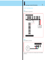
Wiring Diagrams for FingerTec® AC900 with AdapTec
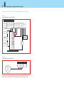
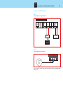
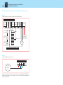
Function: Time Attendance Only
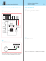
Step 1
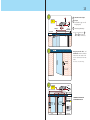
Connect AdapTec to FingerTec® AC900
Siren
Accept
0
Relay
Access Control/Power Output Module
Siren
Output
12V EM
OK 12V MAX 0.5A
0
0
12V
Output
Voltage
Tamper
Switch
Input
EXT. Door To Battery
I/P
Exit
0
C
12V
12V
NC
0
-
+
GND
PWR
COM
DC 12V
Rechargeable
Backup Battery
NO
NC
GND
AL+
ALBUT
GND
B+
B-
Connection Points in FingerTec® AC900
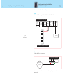
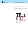
Step 2
Connect AdapTec to a power source
Power Supply/Power Input Module
L
N
E
-V
+V
AC110/240V
L - Live
N - Neutral
E - Earth
Now you can turn on the power source and using the system for time attendance
purpose only.