1
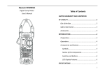
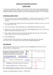
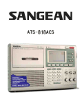
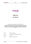
INTIEL THE ELECTRONICS ON YOUR SIDE Controller for cooling chambers and heat pumps type: CMHP User’s Manual Bulgara Pomorie www.intiel.com str. “Peter Beron”, № 9 tel:+359596/33366 fax: +359596/32580 e-mail:[email protected] 2 1. Application The controller is designed to drive cooling chambers or heat pump type air - air, air - water, water – water operating with one or two compressors. 2. Operation The regulation is performed by a temperature in the chamber when it is cooling chambers or by outlet temperature when heat pumps (sensor T1) according to the set temperature. In heat pump unit operates in heating or cooling, depending on the selected mode Compressor operation: Cooling or Cooling chamber heating 10V output 0-10V 0V Т1 К2 К1 Hys Hys/2 Тset Hys/2 Т1 – outlet temperature, or temperature within the chamber Тset – setting К1,К2 – compressors Хис – hysteresis Hys Of the graph is shown working with two compressors for constant load they take turns (which first turn on, turn off first). Fans operation: heating cooling 10V 0V output 0-10V Т3 В2 Т2 В1 Hys Тset Т2,Т3 – temperature of the evaporator / condenser Тset – setting В1,В2 – fans Хис – hysteresis Hys Of the graph shows operation of the fans by evaporator temperature / condenser (sensors T2, T3), where the option is selected to work with the compressor graph is analogous to the work of the compressors. (see settings fans) 3 Operation of defrosting: Defrosting is performed only in "Heating" or option cooling chamber. output 0-10V К1 Т2– evaporator temperature T4 – ambient temperature dT – temperature difference К1– Compressor В1 – Fan RV – вентил за обръщане на посоката RV Delay at Start time dropping В1 Delay at end Т2 dT=T4 – T2 ; T2<0 time of entry into defrosting Time of the end defrosting Start Т End defrost. End The graph shows the defrosting by the compressor and reversing the direction in systems with only one compressor. Defrosting can be done only by heaters or fan in refrigerators, not allowed reversal of the freon (RV = 0) and the heater (heater = 0). (see defrost settings) Start defrosting happens at the time or at the temperature difference (dT) between surrounding temperature (sensor T4) and the temperature of the evaporator / condenser (sensor T2, T3). End of defrosting happens when the temperature reaches T2 of the end or at the timeand in this case error message displays. The next exit on the temperature error will be cleared. In the refrigerating chambers entry into defrost run only during. 4 3. Front panel 1 2 3 4 1 – display; 2 - button to change the "Next"; 3 - button to change "back"; 4 - button to enter / exit the programming mode, start / stop on hold for about 5 seconds (Sw2); Description of the display: 3 2 4 1 5 13 12 11 10 9 8 7 6 1 - measured temperatures; 2 – application; 3 – setting of the maintain the temperature; 4 – setting fans temperature; 5 – setting a temperature difference of entry into defrost; 6 – presence of error message; 7 - operating valve reverse; 8 – heating mode / cooling mode ; 9 – defrost; 10 – switched on defrost heater; 11 – operation the fans; 12 – compressor operating or clock flashing (time); 13 – pump operation at air / water and water / water, - fan in an air / air and in cooling chamber; 5 4. Programing Setting parameters are divided into two groups. General open access and service access with a password. 4.1 General settings. With the buttons "▲" or "▼" scroll until the display shows the current temperatures menu, then press "▄": Common Settings *Theat 50°C Tcool 20°C Hys 10°C EXIT To select a setting, move the cursor "*" with buttons "▲" or "▼", to make a change and return to the choice of setting press "▄". Setting that changes start flashes, with buttons "▲" or "▼" can change its value. After completing the settings, select "EXIT" and press "▄" to save the changes. name meanings limits factory settings Heat setting Cool setting hystiresis Theat Tcool Hys -30 – 80 °C -30 – 80 °C 2 – 20 °C 50 °C -20 °C 5 °C (note) 4.2 Setting service. With the buttons "▲" or "▼" scroll until the display shows "Service settings", then press "▄". The password is 123. The numbers are introduced successively 1, 2 and 3 after each digit press button "▄". 4.2.1 Settings for the compressors. With the buttons "▲" or "▼" scroll until the display shows "Compressor settings", then press "▄". To select a setting, move the cursor "*" with buttons "▲" or "▼", to make a change and return to the choice of setting press "▄". Setting that changes flashes, with buttons "▲" or "▼" can change its value. After completing the settings, select "EXIT" and press "▄" to save the changes. name meanings limits Number of compressors Delay at ON Count of compr. 1–2 factory settings 2 Delay at ON Min. time work Min. time OFF 0 – 255 s 0 – 255 s 0s 0s 0 – 255 s 0s 0 – 255 s only refrigerating chambers 0s Min. time work Min. time OFF Stop after off the valve /FV/ Stop after FV 6 (note) 4.2.2 Defrost settings. With the buttons "▲" or "▼" scroll until the display shows the inscription "Defrost settings", then click "▄": For selection of setting. Move the cursor "*" with buttons "▲" or "▼", to make a change and return to the choice of setting, press "▄". Setting that changes flashes with buttons "▲" or "▼" can change its value. After completing the settings, select "EXIT" and press "▄" to save the changes. name meanings limits factory settings dT 0 – 30 °C 10 °C T for end 0 – 20 °C 20 °C Start by time 0 – 900 min 0 min End by time 0 – 255 min 0 min Delay at start 0 – 255 s 0s meanings limits factory settings Dripping time Heater Delay at end Dripping time Heater En/Dis 0s 10 s 0 Reversing valve Rev. val. En/Dis Type of unit Type of unit 0 – 255 s 0 – 255 s En – 1 Dis – 0 En – 1 Dis – 0 Air / Air – 1 Air / Water – 2 Water / Water – 3 Fridge – 4 Temperature difference for entry into defrost Temperature for end defrost Entry into defrost by time End defrost by time Delay at start name Delay at end (note) (note) 0 1 4.2.3 Fans settings. With the buttons "▲" or "▼" scroll until the display shows the inscription "Fan settings", then click "▄": For selection of setting Move the cursor "*" with buttons "▲" or "▼", to make a change and return to the choice of setting, press "▄". Setting that changes flashes with buttons "▲" or "▼" can change its value. After completing the settings, select "EXIT" and press "▄" to save the changes. 7 name meanings Heat seting Tset_heat limits -30 – 80 °C factory settings 30 °C (note) --- с компресора Cool seting Tset_cool -30 – 80 °C 0 °C --- с компресора Hysteresis Hysteresis 2 – 20 °C 10 °C 4.3 Error note With the buttons "▲" or "▼" scroll until the display shows the inscription "Error messages", then press "▄": To clear the error position the cursor "*" with buttons "▲" or "▼" to "Reset Alarms" and press "▄", or turn off and on by holding the button "▄". name Low pressure meanings LowP limits OK / Err factory settings stops the compressor and fan stops the compressor and fan at refrigeration chambers fan stops and after 60 s and the compressor stops, START/STOP when another application stops the compressor and fan (Reset) atomatically High pressure HighP OK / Err Door switct Or external switch ON/OFF (Sw1) Door (Stop) OK / Err Flow sensor Flow sens OK / Err Defrosting compressor 1 Defrosting compressor 2 Defrost 1 OK / Err - atomatically Defrost 2 OK / Err - atomatically 8 manual atomatically manual + – + – Fan 2 0 – 10V Heat Cool Flow T4 T3 Fan 1 0 – 10V T2 Compr. 0 – 10V T1 Door (Stop) HP data and electrical connection LP 5. Technical + – 24 25 26 27 28 29 30 31 32 33 34 35 36 37 38 39 40 41 42 43 44 45 46 47 1 2 3 4 5 6 7 8 9 10 11 12 13 14 15 16 17 18 19 20 21 22 23 Pump Fan FV Reverse valve heater Fan 2 Fan 1 Compr. 2 Compr. 1 L N - Inputs "LP", "HP", "Flow", "Door" should be closed for normal operation when not in use put a bridge between the terminals. - Input "Heat / Cool" in open contact mode is "heating" mode "cooling" at closed contact. Technical data: Supply voltage Sensors Pt 1000 temperature Inputs contact sensors Relay output Analog outputs Measuring range Measurement unit Humidity Degree of protection ~ 230V/50Hz (-50 to +250 ° C) independent contact contact ~ 220V/3A 0 - 10V/max.10mA -30 +100 ° C 1°C up to 80% IP20 9 6. Example of application Air/air air / water Fan 2 Fan 1 T2 T4 T3 condenser Fan 1 condenser T2 T4 Fan 2 Flow T1 T3 condenser condenser T1 heater heater heater RV evaporator evaporator heater RV RV RV Pump (Fan) HP LP Compressor 2 HP LP Compressor 1 Pump (Fan) HP LP Compressor 1 HP LP Compressor 2 Shown in the diagram have a reversal of the hot vapor from the compressor. When there is a defrost by reverse warm air or water the flap or valve reverse connect in place of the heater and choose the option to defrost heater. In the system air / air, the main ventilator is connected to the terminals of a pump. Water/water cooling chamber Cooling volume Door Flow T1 T4 T2 condenser Fan 1 RV RV LP HP Compressor 1 Pump (Fan) Evaporator Condenser heater heater RV T3 Evaporator heater evaporator T2 heater Fan 2 T1 T3 condenser RV HP LP Compressor 2 HP LP Compressor 1 Pump HP LP Compressor 2 In the cooling chamber when the compressor is stopped by gathering freon, freon valve connects to the place of the pump. 10 7._____________________________________________________ ________________________________________________________ ________________________________________________________ ________________________________________________________ ________________________________________________________ ________________________________________________________ ________________________________________________________ ________________________________________________________ ________________________________________________________ ________________________________________________________ ________________________________________________________ ________________________________________________________ ________________________________________________________ ________________________________________________________ ________________________________________________________ ________________________________________________________ ________________________________________________________ ________________________________________________________ ________________________________________________________ ________________________________________________________ ________________________________________________________ ________________________________________________________ ________________________________________________________ ________________________________________________________ ________________________________________________________ ________________________________________________________ ________________________________________________________ ________________________________________________________ ________________________________________________________ ________________________________________________________ ________________________________________________________ ________________________________________________________ ________________________________________________________ ________________________________________________________ ________________________________________________________ ________________________________________________________ ________________________________________________________ 11 8. Warranty The warranty period is 24 months following the purchase date of the unit or its installation by an authorized Engineering Company, but not exceeding 28 months after the production date. The warranty is extended to the malfunctions that occur during the warranty period and are result of the production reasons or defective used parts. The warranty does not relate to malfunctions corresponding to notqualified installation, activities directed to the product body interference, not regular storage or transport. The repairs during the warranty period can be done after correct filling of the manufacturer warranty card 12