1
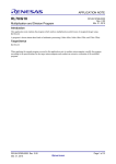
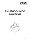
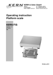
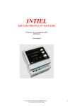
INTIEL
THE ELECTRONICS ON YOUR SIDE
Heating circuit controller - four channels
INT 0129-4
User’s Manual
1. Application
The device is designed to control motor actuators of mixed valves, in accordance with the
water temperature directed to the heating system. There is a possibility to manage three two way
valves and one analogue actuator 0-10 V. It is suitable for buildings, where the installation is
fulfilled with one to four heating circuits, like fan-coils, under-floor and radiator heating, as well
domestic hot water preparation.
Application scheme:
T2
T1
T3
Р3
Р2
Р1
T4
Р4
0 – 10V
М
М
М
М
T_reverse
2. Operation
The device operates in heating or cooling mode, as it can be switched by the input for mode
selection.
The water temperature assignation in heating circuit in heating mode can be done by one of
the following ways: manually, from the controller, according the outdoor temperature or by
means of a room thermostat. It can be selected only one of those three options (see part
“Adjusting the assigned temperature”).
The room thermostats is to be contacts type.
The water temperature assignation in the heating circuit in cooling mode can be done by one
of the following ways: manually, from the controller or by means of a room thermostat.
The regulation can be provided by means of impact of the motor actuator installed on the
mixed valve.
The device is equipped with a weekly timer, which affects to all four channels in order to keep
a save /economic/ temperature.
2.1 Two positional motor actuators:
The Controller manage the operation of those actuators sending signals alternating operation
and pause periods. The relation between the operation and pause signals relates to:
- Operation time period “Vper”;
- The regulation zone “Zone_reg” and
- The temperature difference between the assigned and current measured water temperature.
Operation of the output concerning actuator “opening” in heating regime and “closing”
in cooling regime
When the measured temperature of the heating water in mixed circle is less than the assigned
one, then the operation direction in heating regime is “opening” and cooling regime is “closing”.
The zone of regulation “Zone_reg” is just before the assignation of the heating water “W”. When
the measured temperature is less than the temperature defined by the regulation zone, then the
actuator works with minimal pauses of at about 3 seconds and duration of the operation impulse
with a 3 seconds less than “Vper”. When the temperature defined by the zone of operation is
being reached then the operation impulses start decreasing, as the pauses start increasing. The
operation impulses have their minimum value of at about 3 sec. as far as the assigned temperature
“W” is being reached and the pauses are being reached their maximum value of “Vper”-3 sec.
The actuator stops when the assigned and measured temperatures become equal as it remains at
the same position until difference of 1°С between the assigned and measured temperature
appears. In case the change relates to decreasing of the heating water temperature, then the same
output remains active, but if it relates to increasing of the same temperature, then the output will
be switched as “closing” one for heating and “opening” for cooling” will become active.
Т, °C
U,
V
toff =Vper –
3
ton toff
closing “heating”
opening“cooling”
Zone_reg
W - zone_reg
W
W+1
+1
W,
t, s
°C
Operation of the output concerning actuator “closing” in heating regime and “opening”
in cooling regime:
When the measured temperature of the heating water in mixed circle is grater than the
assigned one, then the operation direction in heating regime is “closing” and cooling regime is
“opening”. The zone of regulation “Zone_reg” is just before the assignation of the heating water
“W”. When the measured temperature is grater than the temperature defined by the regulation
zone, then the actuator works with minimal pauses of at about 3 seconds and duration of the
operation impulse with 3 seconds less than “Vper”. When the temperature defined by the zone of
operation is being reached then the operation impulses start decreasing, as the pauses start
increasing. The operation impulses have their minimum value of at about 3 sec. as far as the
assigned temperature “W” is being reached and the pauses are being reached their maximum
value of “Vper”-3 sec. The actuator stops when the assigned and measured temperatures become
equal as it remains at the same position until difference of 1°С between the assigned and
measured temperature appears. In case the change relates to increasing of the heating water
temperature, then the same output remains active, but if it relates to decreasing of the same
temperature, then the output will be switched as output “closing” will become active during
heating and output “opening” during cooling.
Т, °C
U,
V
open „heating”
Zone_reg
cloe „cooling”
toff
W–1
toff =Vper –
3
ton
W,
t, s
°C
W + zone_reg
W
2.2 Proportional actuators:
The zone of regulation ”Zone_reg” is just before the assignation /„W”/ of the heating water in
mixed circle in heating mode and just after the assignation /”W”/ of the heating water in mixed
circle in cooling regime.
Heating mode. The controller sends to the actuator a maximum signal of 10V when the
measured temperature of the heating water is less than the one defined within the regulation zone
“Zone_reg”, as with reaching the regulation zone the control signal will start changing (0-10V).
The signal changing is active until the temperature is within the regulation zone. It is being sent a
minimum control signal of 0V, when the measured temperature of the heating water is grater than
the assigned one.
Cooling mode. The controller sends to the actuator a maximum signal of 10V when the
measured temperature of the heating water is grater than the one defined within the regulation
zone “Zone_reg”, as with reaching the regulation zone the control signal will start changing (010V). The signal changing is active until the temperature is within the regulation zone. It is being
sent a minimum control signal of 0V, when the measured temperature of the heating water is less
than the assigned one.
zone_reg
zone_reg
U,V
1
0
cooling
heating
W - zone_reg
T,°C
W
W + zone_reg
W,
°C
2.3 Temperature limitations:
- Minimum and maximum temperature assignation in heating mode (WlimH);
- Minimum and maximum temperature assignation in cooling mode (WlimC);
- Minimum temperature level of the return water in heating mode.
Minimum and maximum temperature of the heating water defines the temperature range
within which the heating water is being sent to the heating system (see part programming
“Service settings”).
The minimum temperature level of the return water protects the heat-exchanger source of
condensation. It is not being sent the complete capacity of the source to the heating systems until
the temperature of the return water it is not being increased above the assigned one. In this case a
caution message occurs on the display (see part programming “Service settings”).
Special features of actuator operation during activation of low return water temperature
(only in heating mode).
If the measured temperature of the return water is lower than the assigned one a caution note
appears and the actuator starts closing the mixed valve, decreasing the power sent to the
premises. /“ATTENTION! <Very low T_rev>”/
Two positional valves:
The room thermostat can be equipped with a contact or analogue output, as the analogue one
can be 0(4) – 20 mA or 0 – 10V /see part “Programming of the room thermostat”/.
The regulation is provided by influence on the motor actuator mounted on the mixed valve, as
the motor actuators can be two positional or proportional ones with a control signal of 0 – 10V.
The following control signals will be made in relation to the difference between the assigned
and current temperature of the heating water:
Т_rev,
U,
°C
V
open
Zone_reg
close
Regulation by
heating water
Т_rev_s - zone_reg
Т,
t, s
°C
Т_rev_s
Proportional actuators:
The controller sends to the actuator a maximum signal of 10V when the measured temperature
of the heating water is less than the one defined within the regulation zone “Zone_reg”, as with
reaching the regulation zone the control signal will start changing (0-10V). The signal changing
is active until the temperature is within the regulation zone. It is being sent a minimum control
signal of 0V, when the measured temperature of the heating water is grater than the assigned one.
U,V
1
0
zone_reg
W
Т_rev/s - zone_reg
Regulation by
heating water
Т_rev/s
Т,
°C
2.4 Adjusting the assigned temperature
A) Heating mode
2.4.1 Manual setting of the heating water assignation (W_heat)
In this case the assignation does not relates to other factors like outdoor and room temperature,
as the selected value is being kept ( see part “Setting of the mixed circuits”).
2.4.2 Adjusting the heating water temperature assignation by means of outdoor
temperature (equi-thermal regulation).
In order of faster heating of the building after first start or long stop of the heating system it
can be switched to manual assignation until the comfort temperature is being reached (see part
“Setting of the mixed circuits”). Then it can be switched again to outdoor temperature
regulation.
- Selection of a temperature region
The temperature region selection fix the curve according which the assignation of the heating
water will be changed in relation to the changes of the outdoor temperature. All curves have a
common point at +20°С, which corresponds to minimum assignation of the heating water.
W_max
W_min
To, °C
-20
-10
0
10
20
- Adjustment of reaction time for outdoor temperature regulation (Tod).
In this case it is being defined the period of time after which the changes of the heating water
temperature calculated by means of the outdoor temperature will be proceeded. In this case it is
being obtained an average value of the heating water assignation by means of the outdoor
temperature for the selected period of time. (see part programming “Service settings”)
For example: the selected curve is(-10+20°С), room delay is 5 hours, outdoor temperature is
10°С and we have current assignation of the heating water 40°С. The outdoor temperature is
being changed as it goes to 7°С, as the temperature of the heating water is to become 46°С. Due
to selected room delay, the heating water assignation will start increasing as the difference of
6°С will be reached at the end of the 5th hour.
Recommended values for the Room delay:
0 – 3 hours for light constructions and halls;
4 – 10 hours for solid built houses;
11 – 30 hours for solid built houses with a good insulation;
2.4.3 Adjustment of the heating water by means of room thermostat (see part
Programming, “Setting mixed circuits”)
The device operates only with a contact type room thermostat equipped with an independent
output.
- Optimization time for contact type room thermostat.
Using the optimization time provides decreasing of variations in heating water assignation,
which provides better regulation of the heating water. It can be chosen from 0 up to 60 min., with
a step of 5 minutes. (see part programming “Service settings”)
Wmax
ON
без оптимизация
ON
с оптимизация
W
W
Wmin
Wmax
OFF
Wmin
OFF
Т,
Т,
°C
°C
In terms of not using an optimization (0) the room thermostat switches on or switches off, as
the assignation of the heating water become:
- maximum, when it is switched on;
- minimum, when it is switched off.
Using an optimization of 5-60 min., in case of room thermostat switching on or switching off,
then the assignation of the heating water is being changed in the following way:
- switching on – start increasing as the maximum assignation is being reached at the end off
the optimization time period and it happens only if during that time switching off does not
appear;
- switching off – start decreasing as the minimum assignation is being reached at the end off
the optimization time period and it happens only if during that time switching on does not appear;
For example: a contact type thermostat is being chosen, optimization time 15 min., state of the
regulator is switched off. The current value of the heating water is 40°С, which means the
regulator will be switched on. Due to entered optimization time the assignation will start
increasing. At the 5th minute the desired temperature is being reached as the regulator is being
switched off. The assignation of the heating water will be increased with 1/3(Wmax-40) and it
will start decreasing, as the decreasing will go on until the regulator will be switched on again.
Wmax
ON
40°С
OFF
Wmin
t,s
The choice of the optimization time depends on the heating water speed (pipeline, radiators),
the system for a room control, the capacity of the heating source (boiler) and the building
insulation.
Recommendations:
1. Room contact thermostats are to be with а hysteresis of 0.5 – 1 °С
2. The optimization time is to be with 5-10 min. grater of the time between two switching
of the room thermostat in the fixed mode. Practically the times can be adjusted according
heating system inertness:
- low inertness systems – (5 – 20) min.
- middle inertness systems – (25 – 40) min.
- high inertness systems – (45 – 60) min.
B) Cooling mode
In this mode the assignation can be made manual or by means of a room thermostat.
In case the assignation is made by means of a room thermostat the operation of the controller
is similar as during heating mode. The difference is that when the room thermostat contact is
closed, then starts room temperature decreasing, as when it is opened increasing of that
temperature. The assigned temperature is being changed within the one adjusted with WlinC /see
part “Setting of mixed circuits”/.
2.4.5 Operation of the pump output:
Heating mode
- operation by force when the water temperature is less than 10 °С.
- stops the pump operation by force in case the temperature of the heating water exceeds its
maximum level with 10 °С, thus protecting the heating circuit against overheating. The same
state is being kept until it occurs a necessity for more capacity in the heating circuit.
- stops in case of no heated water at the heating circuit inlet. The pump output is being
switched off in case the measured temperature of the heating water is lower than the assigned
minimum one in 1 hour. Then, the controller goes into test mode as every 15 minutes the pump is
being switched on for 5 minutes. The previous mentioned state goes on until the heating water
exceeds the assignation for the minimum water temperature level.
During both Heating and Cooling modes:
- normal operation in case of necessity of sending power to the heating circuits;
- it stops in case of no need of sending power to the heating circuits. If the mixed valve is
being closed for more than one hour, then the pump is being stopped. The state goes on until a
necessity of power does not arise.
2.4.6 Operation of the week timer.
There are two programs for economical temperature (Teco) with time periods of 0 – 24h,
concerning each day of the week. The weekly timer affects to all channels at the same time.
If the timer operation is allowed when the relevant hour and day in the week comes, the
assigned temperature (W) is being changed depends on the assignation way as:
heating
Ctrl Man. WminH
Ctrl Rreg Does not
affect
Ctrl Tout W – 10°C
cooling
WmaxC
Does not
affect
Does not
affect
Example: let fix economic temperature during every workday within 18:30 – 06:00, as during
the weekend concerning the whole days.
Setting Programm1
<Weekly timer >
Prog1 Teco from
* 18:30 to 06:00
MoTuWeThFr – –
Setting Programm2
<Weekly timer >
Prog2 Teco from
* 00:00 to 24:00
– – – – – SaSu
Then the timer is to be switched on
<Weekly timer >
time&d 10:00 Mo
*Timer
Enable
EXIT
(see part programming “week timer”)
In case of setting same end and start time, the program is not active
3. Front panel
status
INTIEL
Н - heating
С - cooling
Number of
смес. кръг
1
Pump 4
8
Pump 3
7
Pump 2
6
Pump 1
5
4 Channel
Control of mixing valves
зададена
температура
2
H 1 | 2 | 3 | 4
S <m>|<m>|<m>|<m>
W 40° | 60° | 80° | 50°
t 40° | 50° | 45° | 60°
3
4
измерена
температура
1 – display;
2 – Button „forward”;
3 – Button „backward”;
4 – Button for entering/escaping programming mode;
5 – indication about circulation pump operation 1;
6 – indication about circulation pump operation 2;
7 – indication about circulation pump operation 3;
8 – indication about circulation pump operation 4;
Description of the status row:
“<” opening direction;
“>” closing direction;
“m” manual assignation
“r” assignation by a room thermostat;
“o” outdoor temperature assignation;
“h” assignation changing by the weekly timer;
4. Programming
4.1 Manual adjustment of the mixed circuits. Press buttons „▲” or „▼” until it is being
shown on the indication “Settings for mixing circuits” and press button „▄”:
* <Mix Cir. No 1 >
W_heat
50°C
W_cool
20°C
Ctrl_heat
Man.
<Mix Cir. No 1>
<Mix Cir. No 1>
* Ctrl_cool
Man. * Zone_reg 5°C
WlimH 15 – 80 °C Vper
15s
WlimC 10 – 30 °C
EXIT
By means of buttons „▲” or „▼” you can move indicator „*”Press button „▄” in order to
confirm. The value assignation starts blinking. By means of buttons „▲” or „▼” can be made
changes. After that choose “EXIT” and press button „▄” to confirm the changes.
Description
Symbols
Limitations
Heating
circuit
number
Heating
assignation
Cooling
assignation
Adjusting
heating
assignation
Mix Cir.
No
1–4
Factory
settings
-
W_heat
WlimН
60 °C
W_cool
WlimC
15 °C
Adjusting
heating
assignation
Min.and
max.
heating
assignation
Min.and
max.
cooling
assignation
Regulation
zone
Mixed
valve
operation
time
Ctrl_cool
Man.(manual)
Rreg(room
thermostat)
T_out(outdoor
temperature)
OFF
Man.(ръчно)
Rreg(стаен рег.)
OFF(изкл.)
WlimН
5 – 90 °C
10 – 80
°C
WlimС
5 – 35 °C
10 – 30
°C
Zone_reg
2 – 20 °C
5 °C
Vper.
15 – 180 s
15 s
Ctrl_heat
Man.
Man.
Current
value(notes)
4.2 Common settings
Review the menu by means of „▲” or „▼” buttons until on the display appears “Common
Set”, as afterwards button „▄” is to be pressed
<Common Set >
*To 15° / Tod 5h
Tcur -10 ÷ 20°C
Trev/s 30 / 40°C
<Common Set>
* Rreg_avr 10 min
Over Tmax P --EXIT
Symbol “*” is to be moved by means of „▲” or „▼” buttons in order to select the parameter
which is to be adjusted. To confirm the changes and return to settings button „▄” is to be
pressed. Setting which is being changed starts blinking, as by means of „▲” or „▼” buttons the
value can be changed. After the settings are being completed “Exit” is to be selected and button
„▄” is to be pressed to save the changes.
Description
Outdoor
temperature/
reaction time
Temperature
curve
Return water
temperature
assignation
Room
thermostat
optimization
time
Сcirculation
pump
stopping if
the heating
water
exceeds its
assignation
with 10C
Symbols
Limitations
Factory
settings
То /Tod
0 – 30 h
0h
Tcur
-20 ÷ 20 °C
- 10 °C
Trev/s
20 – 70 °C
30 °C
Rreg _opt
0 – 60 min
15 min
---(forbidden)
OFF(разрешено)
---
Over_Tma
xP
Current
value(notes)
4.3 Weekly timer. By means of buttons „▲” or „▼” the menu can be reviewed until on the
indication appears “weekly timer”, as afterwards button „▄” is to be pressed.
<Weekly timer
<Weekly timer
<Weekly timer
>
>
*time&d 10:00
Prog2 Teco from
Prog1
Teco
Mo
* 00:00 to 24:00
from
to be moved
or „▼” buttons in order to select the parameter
– –by means
– – of– „▲” Timer
*Symbol
21:00“*” is to
Disable
06:30is to be adjusted.SaSu
which
To confirm the changes
and return to settings button „▄” is to be
MoTuWeThFr
pressed. Setting which is being changed starts blinking,EXIT
as by means of „▲” or „▼” buttons the
– – can be changed. After the settings are being completed “Exit” is to be selected and button
value
>
„▄” is to be pressed to save the changes.
Setting program 1 (Prog1) and program 2 (Prog2) – it can be adjusted period from 00 to 24 h,
with a step of 15 minutes. It can be chosen every day of the week from Monday to Friday or
Saturday or Sunday.
Setting the clock (time&d) – it is being adjusted current time (hour: minutes) and day of the
week.
Timer switching on – it can be selected from Enable/Disable.
4.4. Messages
The following messages can be reviewed on the display, according the situation:
- The devise is stopped from the control input - “Stopped from switch ON/OFF”;
- The measured return temperature water is lower than the assigned one “ATTENTION!
<Very Low Trev>”
- Normal state - “<Status is OK!>”
-
Room thermostat staus – from “<Status is OK!>” button „▄” is to be pressed as the
following message appear
Room
regulators
1 | 2 | 3 |
4
ON| OFF| ON|
ON
Status
Press the same „▄” button again to return.
T4
T_rev
On/Off
Heat
Cool
Rreg4
Rreg3
SM
M4
To
+
L
N
PE
4
5
28
29 30
6
7
31
8
32
33 34
9
10
SM2
com
11
open
3
26 27
close
2
25
close
24
open
23
close
1
21 22
open
20
SM3
35
36
12
37
13
38
39
14
15
Р2
40
41
16
Р3
17
42
–
0 – 10V
T3
T2
T1
Rreg2
Rreg1
6. Electrical connections and technical data
43 44 45
18
19
Р4
M
SM1
SM – серво мотор
Р1
- Input “ON/OFF” is to be closed for normal operation. In case that input is not being
used, a bridge is to be placed between terminals 42 and 43.
- input “Heat/Cool”. If the contact is open the active mode is “Heating”, when it is closed
the active one is “Cooling”
- Room thermostats inputs. If the contact is closed the state is ON and if it is open the
state is OFF.
Recommendation with the installation::
- sensor for heating water T1-T4 it is to be mounted on the outlet pipe after the mixed valve.
- return water sensor T_rev – it is to be mounted on the inlet pipe of the heat exchanger
(boiler). The sensor is not to be connected to the controller in case there is no necessity of
observing the return water temperature.
- outdoor temperature sensor To – it is to be mounted on the north outer wall of the building
protected by direct sun shine and wind. It is not recommended to be installed close to heating
sources (chimney, windows, doors, etc.), as well under eaves and balconies.
- room thermo regulator Rreg1 – Rreg4– it is to be installed at the most occupied room at a
place protected of direct sunshine and internal heating sources (stoves, other electrical
appliances, etc.)
- Synchronization of the motor actuator with the valve. Turn into heating regime, separate the
valve and the actuator and disconnect the heating water sensor T. Turn the valve manually in
close direction to complete closed position. Check the actuator out if it moves in the same
direction in which the valve was tuned, as it has to be corrected in case of not matching the
same direction. It has to be waited for until the actuator fulfills its complete move, as
afterwards it is to be mounted on the valve and connected heating water sensor T.
Technical data:
Power supply
Temperature sensors
Room thermostat input
Two way actuator output
Circulation pump output
Control signal
Measurement range
Unit of measurement
Humidity
Protection
~230V/50Hz
Pt 1000 (-50 до +250 °С)
independent contact
simistor max~230V/0,25A/50Hz
switching contact ~220V/3A
0 – 10V/max.20mA
-30 +130 °С
1 °С
up to 80%
IP20
7. Warranty
The warranty period is 24 months following the purchase date of the unit or its installation
by a qualified staff, but not exceeding 28 months after the production date. The warranty is
extended to the malfunctions that occur during the warranty period and are result of the
production reasons or defective used parts.
The warranty does not relate to malfunctions corresponding to not-qualified installation,
activities directed to the product body interference, not regular storage or transport.
The repairs during the warranty period can be done after correct filling of the
manufacturer warranty card
Warranty Card
Manufacturer: INTIEL
Product type
Production number
Production date
Dealer’s confirmation
Purchase date
Invoice number
Dealer’s name, address and
stamp
Seller’s name and signature
Installation date
Date
Company (address, stamp)
Installer’s name and signature