1
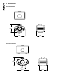
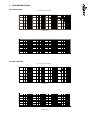
pa s s i v e
owner’s manual
CONTENTS
1 INTRODUCTION
2 THE BASICS
2.1Unpacking and visual checks
2.2Preliminary recommendation
2.3 Connecting your speakers
2.4Observing polarity
2.5 Power Amplifiers
3 INSTALLING & POSITIONING
3.1Surround Monitoring
3.2 Bass Ports
3.3Equalisation
4 EXTERNAL DIMENSIONS
5 PERFORMANCE DATA
6 TECHNICAL SPECIFICATIONS
7 SERVICING
7.1 Cabinet finish
7.2 Driver removal
7.3 Crossover
8 WARRANTY
9 DECLARATION OF CONFORMITY
1
INTRODUCTION
Thank you for purchasing Tannoy Ellipse Passive Monitors.
Designed and manufactured by Tannoy and incorporating new Dual Concentric™ designs these monitors are suitable
for desk-top or 5.1 surround situations at near and mid field monitoring positions. Unlike discrete systems with separate
low frequency and high frequency drive units mounted on the front baffle the Dual Concentric™ single point source
properties and characteristics eliminate horizontal and vertical dead spots around the crossover region and maintain
flat phase and amplitude performance across the audible band. A WideBand™ SuperTweeter™ extends the amplitude
response of the loudspeaker to beyond 50kHz which results in an extended time and phase response within the
audible band.
Both Ellipse 8 Passive and Ellipse 10 Passive share the same acoustic balance and dispersion characteristics, and both
types can be used in a single 5.1 surround monitoring situation. For example the Ellipse 10 Passive can be used as a
centre channel where more power is delivered and the Ellipse 8 Passive installed as effects/surround channels. During
mixing and playback both models provide a very accurate soundstage retaining natural voicing to ensure that aural
effects and speech localisation pan from left to right and front to rear seamlessly.
The Ellipse 8 Passive and 10 Passive are magnetically shielded, permitting use in close proximity to more traditional
CRT TV monitors without causing colour-fringing effects.
This manual is intended to provide you with some useful advice on how to install and use the loudspeakers, as well as
providing more technical information about system design and detailed specifications. The goal is to help you get the
best results possible.
2
THE BASICS
The Ellipse 8 Passive and 10 Passive monitors are designed and made by Tannoy, a company with unrivalled experience
in studio monitoring. They have an extremely detailed, dynamic sound with a wide, flat frequency response - essential
requirements for monitoring with reliable accuracy.
The Dual Concentric™ drivers contain both low frequency and high frequency drive unit components aligned along the
same axis and positioned to generate an acoustic point source. A titanium dome SuperTweeter™ extends the amplitude
response of the acoustic radiation beyond the limit of human hearing to above 50kHz. Extending the amplitude response
in this way corrects the time and phase response of the system within the audible band below 20kHz. A rear switch on
each monitor sets this feature on or off for comparison between WideBandTM and conventional monitoring.
The Dual Concentric™ components and the SuperTweeter™ are seamlessly matched by a precision low-loss crossover
network. The drive units are mounted on a baffle of elliptical shape to minimise diffraction and create distinctive styling.
2.1 UNPACKING AND VISUAL CHECKS
The Ellipse 8 Passive and Ellipse 10 Passive are individually packed and cushioned for safe transit. To remove
the speakers from the carton without damage, open the end flaps fully and bend them right back. Turn the package
upside-down on the floor and lift the carton vertically upwards to leave the speaker resting on the packing trays.
Inspect each speaker for signs of transit damage. Nothing on or in your speakers should be loose or rattle about.
In the unlikely event of damage having occurred, inform the carrier and the supplier immediately.Keep all the packaging
as this will show evidence of the damage or excessive handling forces. It is also a good idea to keep the packaging if
possible for future transportation.
2.2 PRELIMINARY RECOMMENDATION
Initially we would like to give a word of warning on high sound pressure levels which these speakers are capable of
generating over sustained periods of time. Levels over 95dB sustained for 8 hours or more per day will eventually cause
permanent hearing loss. Because Tannoy monitors have very low levels of time, amplitude and frequency distortion it is
not always obvious that the sound level is high while working with them. For continuous exposure we recommend the
regular use of a sound level meter capable of integrating the sound level over a period of exposure according to noise
control standards. This is an Leq measurement and should be used to check that sound levels are always within
safety limits.
2.3 CONNECTING YOUR SPEAKERS
The types of cable used to connect the speakers to the power amplifier will marginally affect the sound. The
cross-sectional area of the cable should be large enough so as not to affect the damping factor; generally a cable
2
with a cross-sectional area of 2.5 mm , or greater is recommended. The Ellipse 8 Passive and 10 Passive terminal
panels offer the option of Bi-Wiring. Bi-Wiring provides the facility for connecting separate feeds from the amplifier to the
Low Frequency and High Frequency sections of the crossover network. This method of connection can provide better
instrument separation, localisation, and imaging depth compared with conventional wiring for the cost of another set of
speaker cables. Bi-Wiring provides for separate feed and return cables for low frequencies and high frequencies, low
and high frequencies being differentiated by the crossover point of the loudspeaker system; please refer to the technical
specifications. This reduces intermodulation effects at high and low frequencies within the cables.
The lower the resistance of the cable between the amplifier and the speakers, the better the damping factor acting on the
speaker. This has been covered in every audio magazine that has ever been written about speakers, so we won’t beat it
to death here. You don’t need to buy speaker cable that costs as much as your speakers. To get the most benefit, select
a finely stranded high purity copper speaker cable and dress the cable ends to prevent “hairs” or stray conductors from
shorting across the terminals. If your amplifier terminals will not directly accept your chosen size of cable, you can trim
down the cable size at the amplifier end. Ensure that the binding post retaining nuts on both the loudspeakers and the
amplifier are screwed down firmly without stripping or over tightening them. Ellipse Passive monitors loudspeakers are
shipped ready for standard cable wiring with shorting bars connecting both halves of the crossover together. Keep the
shorting bars in place whilst connecting your cable if not using the Bi-Wire facility.
To Bi-Wire your loudspeakers remove the shorting bars completely from the terminals of the crossover panel. Prepare
2 sets of cables for each loudspeaker, labeling one for HF (High Frequencies) and the other for LF (Low Frequencies)
paying particular attention to the polarity of the conductors within the cable. Keep positive and negative conductors
(Red and Black) connected to the respective red and black terminals. Parallel both positive conductors and both negative
conductors together for the left hand cables at the left hand amplifier terminals. Repeat for the right hand loudspeaker
and conductors at the right hand amplifier terminals.
2.4 OBSERVING POLARITY
You already know about connecting the positive terminal on the amplifier to the positive terminal on the speakers, and
ensuring that both channels are “in phase” by checking to ensure that there’s more bass with both speakers on and
not less bass. Absolute polarity is a bit trickier to confirm but is nevertheless very important. Absolute polarity is the
maintenance of a positive pressure wave from the microphone capsule all the way through to the listener. A kick drum, for
instance, has the drum skin whacked by the foot pedal, and it pushes the air, which pushes the microphone diaphragm,
which generates a signal through the electronics and should eventually come out of the speakers as a positive acoustic
pressure wave. This means the speaker cones will move towards you, just like the drum skin. All Tannoy monitors have
absolute positive polarity which means that a positive going electrical input pulse to the red terminals will move the cones
towards you. However, you can’t trust a conventional recorded source to test this because there is no way to confirm that
absolute polarity was maintained throughout the recording chain; it can even change from track to track. This isn’t a trivial
thing, especially when you’re using a true stereo microphone setup, or trying to accurately place things in your mix. This
is something that should be rigorously checked with every microphone and every signal line in a studio; but the first step
would be to use the kick drum test described above with a few microphones. If you don’t believe it can make a difference,
set up a little test using a mix you know and flip the polarity of both monitor channels at the same time. The imaging will
flip from vague (negative polarity) to strong (positive polarity).Hear-Believe!
2.5 POWER AMPLIFIERS
The power amplifier should be reasonably well matched in power to the power rating of the speakers (see specifications).
The use of a more powerful amplifier (i.e. in excess of the recommended figure) provides increased headroom, which
is useful especially for highly dynamic programme material. Due to the high peak power handling of Tannoy monitors,
responsible use of more powerful amplifiers should not represent a danger to the speakers as long as the amplifiers are
not overdriven.
3
INSTALLING AND POSITIONING
When choosing a suitable location for the monitors, bear in mind that the physical mounting of loudspeakers and their
proximity to room boundaries can have a large influence on performance. For best results the monitors should be
mounted on a heavy rigid structure, supported on four pads making contact with the base of the loudspeaker. The use of
small pads of rubber, Sorbothane, or Blu-Tak is recommended.
Ensure that the console position does not obscure the direct sound radiation from the loudspeakers when sitting at the
mixing position. The engineer and producer should have a clear, uninterrupted view of the monitor loudspeakers.
3.1 SURROUND MONITORING
To ensure a uniform acoustical monitoring environment the room should be symmetrical about the centre or dialogue
loudspeaker axis and any acoustic room treatments should be applied symmetrically on either side of the room. Mixed
“Live end/Dead end” environments should be avoided. If the effects or surround sound loudspeakers are positioned close
to walls then the constitution of the wall surfaces should be identical.
When using either Ellipse 8 Passive or 10 Passive as the main effects speaker for the front soundstage, placement is
a critical factor for good performance. In all cases the centre channel speaker should be placed as close to the viewing
screen as possible. The viewing position when seated determines the ideal mounting height, but in all cases this should
be as close as possible to ear height. If this is not possible the monitor should be tilted towards ear height in the mix
position. The centre speaker should be positioned along the centre axis of the picture and the left/right monitors just
outside the picture. Ideally the three front effects speakers should be placed with the front baffles in line with the screen
surface. If an acoustically transparent screen is used, the left/right monitors should be placed just inside the edges of
the picture. The surround speakers should be positioned at the same distance from the mix position as the main front
speakers.
11
A Subwoofer is recommended, chosen from the Tannoy range to ensure compatibility. The Subwoofer/LFE channel
produces low frequencies which are non-directional and therefore the Subwoofer can theoretically be placed anywhere
in the room. However, from experience, optimum performance will be gained by placing the subwoofer in the same plane
as the main front speakers. The LFE channel is set at a level 10dB higher than the other channels when mixing therefore
it is important to apply the same in any playback situation.
3.2 BASS PORTS
The Ellipse Passive monitors’ bass ports are located on the front panel. You should keep the back panels at least 300mm
(12”) away from the nearest wall surface to avoid an overblown bass sound. If you cannot avoid being close to a wall you
may want to consider plugging the port tubes on your Ellipse 8 Passive monitors with the closed cell foam-rubber plugs
supplied as an accessory within the pack. They are a friction fit for a full seal. This will overdamp the bass alignment of
the monitors making them more suitable for 2Pi environments such as for example against a wall or mounted on a large
flat surface. Ellipse 10 Passive monitors should be equalized electronically in these circumstances.
3.3 EQUALISATION
Our feeling is that you shouldn’t need to equalise monitors at all in a well designed monitoring environment; apparent
12
variations
in the monitor response should be fixed through room design or speaker placement. But we realise that
equalisation is sometimes a necessary evil especially in small rooms or where the monitors are close to room
13
boundaries.
We recommend a good quality speaker controller with digital filtering. Any frequency shaping should be low
Q, smooth and you should make use of shelving responses in the frequency range 200Hz to 800Hz. No two adjacent 1/3
14
octave bands should differ by more than 1dB. If you have a choice of equalisers for monitor applications, less is more.
The
15 fewer the number of filters, the better the equaliser will sound. Over equalisation can reduce system headroom,
and introduce phase distortion resulting in greater problems than cures. Always check out the result of equalisation by
listening
to well recorded vocals or male and female speech from a familiar source.
16
17
18
19
20
4
DIMENSIONS
Ellipse 8 Passive
372.5
[14.66"]
R
WIDEBAND
TM
TECHNOLOGY
210.0
[8.27"]
460.0
[18.11"]
320.0
[12.60"]
ELLIPSE 8 PASSIVE
ellipse 10 passive
423.0
[16.65"]
R
WIDEBAND
TM
TECHNOLOGY
250.0
[9.84"]
540.0
[21.26"]
ELLIPSE 10 PASSIVE
350.0
[13.78"]
5
PERFORMANCE DATa
Ellipse 8 Passive
1m on-axis frequency response
1m on-axis frequency response
Sensitivity Mag. dB SPL Watt
100
90
80
70
60
50
10
100
1000
10000
100000
10000
100000
10000
100000
10000
100000
Frequency(Hz)
(Hz)
Frequency
Impedance vs frequency
Impedance vs frequency
50
Impedance (Ohms)
45
40
35
30
25
20
15
10
5
0
10
100
1000
Frequency
(Hz)
Frequency
(Hz)
ELLIPSE 10 PASSIVE
1m on-axis frequency response
1m on-axis frequency response
Sensitivity Mag. dB SPL Watt
100
90
80
70
60
50
10
100
1000
Frequency (Hz)
Frequency (Hz)
Impedance vs frequency
Impedance vs frequency
40
Impedance (Ohms)
35
30
25
20
15
10
5
0
10
100
1000
Frequency (Hz)
Frequency (Hz)
6tECHNICAL SPECIFICATIONS
Ellipse 8 Passive
Ellipse 10 Passive
Frequency Response (-3dB) 1
55Hz - 40kHz
42Hz - 40kHz
Frequency Range (-10dB) 1
38Hz - 50kHz
30Hz - 50kHz
System Sensitivity (1W @1m) 2
89dB (1W = 2.83V into 8 Ohms)
89dB (1W = 2.83V into 8 Ohms)
Dispersion (-6dB)
90 degrees fully axi-symmetrical
90 degrees fully axi-symmetrical
Driver Complement
200mm (8”) Tannoy Dual Concentric™ 250mm (10”) Tannoy Dual Concentric™
25mm (1”) WidebandTM SuperTweeter™ 25mm (1”) WidebandTM SuperTweeter™
CrossoverPassive 1.5kHz and 14kHzPassive 1.4kHz and 14kHz
Rated Maximum SPL 2
115dB (peak) 116dB (peak) Power Handling
100W (average) 200W (programme)
125w (average) 250W (programme)
Recommended Amplifier Power
200W @ 8 Ohms
250W @ 8 Ohms
Nominal Impedance
8 Ohms
8 Ohms
Distortion
<0.5%
<0.5%
Construction
Cabinet volume / LF alignment
19.5 litre/ reflex ported
32.6 litre/ reflex ported. Integral acoustic resonator.
Cabinet construction
Laminated birch/MDF baffle, internal bracing, detachable neoprene base.
Laminated birch/MDF baffle, internal
bracing, detachable neoprene base.
Finish
Textured black paint.
Textured black paint.
Connectors
4 x 4mm gold plated binding posts (bi-wirable)
4 x 4mm gold plated binding
posts (bi-wirable)
ControlSuperTweeter™ on/off switch mounted SuperTweeter™ on/off switch mounted
on rear termination panel
on rear termination panel
Dimensions (H x W x D)
373 x 460 x 350 mm
14.68 x 18.11 x 13.78”
423 x 540 x 380 mm
16.65 x 21.26 x 14.96”
Weight
13.5kg (29.7lbs)
17.5kg (38.5lbs)
Notes
1. Average over stated bandwidth. Measured at 1 metre on axis.
2. Unweighted pink noise input, measured at 1 metre in an anechoic chamber
A full range of measurements, performance data, and Ease™ Data can be downloaded from www.tannoy.com
Tannoy operates a policy of continuous research and development. The introduction of new materials or manufacturing methods will
always equal or exceed the published specifications, which Tannoy reserves the right to alter without prior notification
7
SERVICING
7.1 CABINET FINISH
To remove marks and scuffs use a soft brush, avoiding the moving parts of the Dual Concentric™ and SuperTweeter™
7.2 DRIVER REMOVAL
Lay the cabinet on its back. Remove the front mounted port tubes which are a friction fit in the cabinet. Remove the front
trim panel using a suitable plastic tool starting aound the port tube holes. Remove the ten hexagonal screws holding
down the Dual Concentric™ driver and set aside. Ease the Dual Concentric™ driver from the front of the cabinet taking
care not to damage the front surface. Remove the driver, note the polarity of the internal connections and disconnect
the internal wiring from both the LF and HF parts of the Dual Concentric™. Take care not to damage the moving parts of
the LF driver. To refit the driver, connect the cables from the crossover to the LF and HF terminals. Fit the driver into the
mounting hole, making sure that the internal connecting cables are not trapped or able to touch the LF cone. Fasten the
screws finger tight and then progressively tighten them down with the appropriate Allen key. Refit the front trim and
port tubes.
To remove the Supertweeter™ housing remove the Dual Concentric™ driver as above. Working inside the cabinet
remove the fixing nut to release the SuperTweeter™ housing and disconnect the cable. Dismantle the housing to release
the SuperTweeter™ capsule which must be replaced completely if faulty. Refit all parts in reverse order ensuring cables
are correctly connected and cannot interfere with moving parts. Some or all of the acoustic absorbent may have to be
removed for access during the dismantling process. Replace each piece in its original position
7.3 CROSSOVER
The crossover is mounted on the rear of the terminal panel. To inspect it, remove the panel by releasing the hexagonal
screws. Take care to avoid undue stress on the cables and components. It is most unlikely that any of the crossover
components will fail during the life of the loudspeaker system.
To remove the crossover completely the cables must be disconnected from the drive units. Please proceed as above to
remove the Dual Concentric™ drive unit and SuperTweeter™ Housing.
8
WARRANTY
NO MAINTENANCE OF THE ELLIPSE MONITORS IS NECESSARY.
All components are guaranteed for a period of five years from the date of manufacture, subject to the absence of, or
evidence of, misuse, overload or accidental damage.
For further information please contact your dealer or the distributor in your country.
If you cannot locate your distributor please contact:
Customer Services, Tannoy Ltd., Coatbridge, Strathclyde, ML5 4TF, Scotland
Telephone: 01236 420199 (UK) +44 1236 420199 (International)
Fax: 01236 428230 (UK) +44 1236 428230 (International)
Internet: http://www.tannoy.com
DO NOT SHIP ANY PRODUCT TO TANNOY WITHOUT PREVIOUS AUTHORISATION
This warranty in no way affects your statutory rights.
9
DECLARATION OF CONFORMITY
The following apparatus is manufactured by Tannoy Ltd of Rosehall Industrial Estate, Coatbridge, Scotland, ML5 4TF
and conforms to the protection requirements of the European Electromagnetic Compatibility Standards and Directives
relevant to Domestic Electrical Equipment. The apparatus is designed and constructed such that electromagnetic
disturbances generated do not exceed levels allowing radio and telecommunications equipment and other apparatus to
operate as intended, and, the apparatus has an adequate level of intrinsic immunity to electromagnetic disturbance to
enable operation as specified and intended.
This equipment conforms to the requirements of the EMC Directive 89/336/EEC, amended by 92/31/EEC and 93/68/EEC
and the requirements of the Low Voltage Directive 73/23/EEC, amended by 93/68/EEC.
Details of the Apparatus:
Tannoy Monitor Loudspeaker
Model Number: Ellipse 8 Passive
Model Number. ELLIPSE 10 Passive
Applicable Standards:EN55103-1:1996 Emission
EN55103-2:1996 Immunity
Electrical Safety EN60065:1993
Signed:
Position:
Date:
For Tannoy Ltd
Director of Engineering
15 May 2009
NOTES
T: 00 44 (0) 1236 420199
T: 00 49 (180) 1111 881
T: 00 33 (0)1 7036 7473
T: 00 1 (519) 745 1158
E: [email protected]
E: [email protected]
E: [email protected]
E: [email protected]
Tannoy adopts a policy of continuous improvement and product specification is subject to change.
6481 0549
Tannoy United Kingdom
Tannoy Deutschland
Tannoy France
TC|Group Americas