1
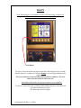
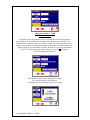
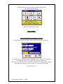
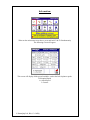
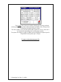
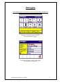
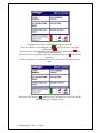
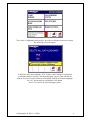
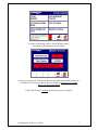
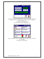
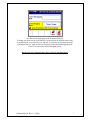
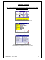
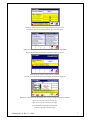
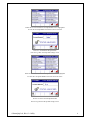
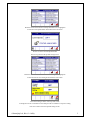
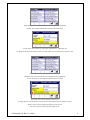
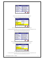
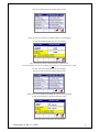
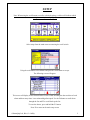
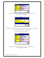
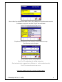
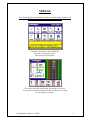
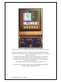
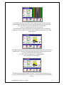
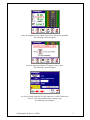
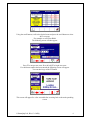
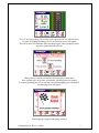
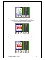
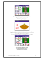
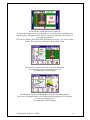
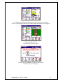
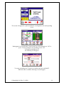
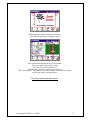
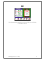
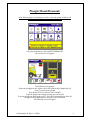
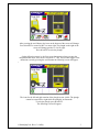
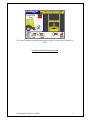
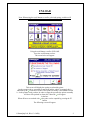
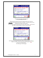
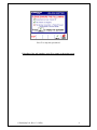
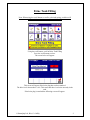
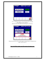
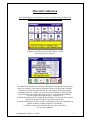
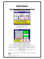
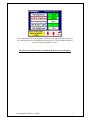
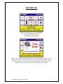
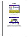
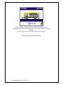
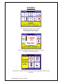
Fleet Supervisor
User Manuals
Road Maintenance Manufacturers,
Syngefield Industrial Estate,
Birr,
Co. Offaly,
Ireland.
Tel: (05791) 20836
Fax: (05791) 21084
E-Mail: [email protected]
Web: www.romaquip.com
© RomaQuip Ltd., Birr, Co. Offaly.
Contents:
Login
Datalogging (Setup)
Spreader Settings (Setup)
Alarms, Edit Drivers, Edit Routes & Clock (Setup)
Spread
Mount/Demount (Plough)
Unloading The Gritter
Brine Tank Filling
Material Calibration
Adjust Display, End Route, Lights & Logout.
© RomaQuip Ltd., Birr, Co. Offaly
LOGIN
Note: When using the scroll button to scroll to a desired setting, a red box will
indicate which setting is currently been highlighted
Scroll Button
The above screen shows the main login screen this will be displayed a few seconds
after the ignition is switched on. Firstly the loading screen will appear then the main
login screen.
The reset switch has to be pressed first before login can commence. The reset
switch is located at the left side of the box.
Spread Rate switch works on any page as long as you are logged in
To login as a supervisor scroll to FLEET SUPERVISOR using the scroll button and
press the scroll button to accept.
The following screen will appear.
© RomaQuip Ltd., Birr, Co. Offaly
Supervisor Number – SUPR
Password – 1234
To input the above login details use the scroll button to select the appropriate
letter and press the scroll button to accept the letter. This has to be done for each
individual letter. When the supervisor number “SUPR” has been inputted press F5 to
toggle to the password box and again using the scroll button scroll to the appropriate
number and press the scroll button to accept. This has to be done for each number.
Press F5 to confirm the login details, if they are correct a will appear.
The screen should look like this.
If the details are correct press and hold F5 to login.
The vehicle number is also displayed.
The following screen will appear for a few seconds.
© RomaQuip Ltd., Birr, Co. Offaly
This shows login was successful and settings are been loaded.
The main screen will appear.
This is the main gritting screen.
Login Complete
If the login details are not inputted correctly
The following screen will appear if either of the login details are incorrect.
The example above shows the Supervisor Number “SUPS” which is not recognized.
To change this, press F5 to toggle to the supervisor number box.
Press F2 or F3 to move the cursor to the letter that needs to be changed, then using the
scroll button select the correct letter and press the scroll button to accept.
Press F5 to login.
© RomaQuip Ltd., Birr, Co. Offaly
Information:
When on the main menu screen above, press and hold F1 & F2 Simultaneously
The following screen will appear.
This screen will display all the spread variables, such as the belt & spinner speeds.
R=Required Speed
A=Actual Speed
I=Current
© RomaQuip Ltd., Birr, Co. Offaly
The example above shows the variables with the truck traveling at 40km/h
with the gritter spreading 2 lanes and hard shoulder (Sp Width: 9.2m), driving in lane
2 with the spread width (Sp Rate) at 30g/m².
The Gate cylinder is set to 98.3mm and the chute cylinder is set too 61.3mm, this is
set automatically depending on the spread pattern required.
The spinner fro example is giving a feedback current of 804Ma, the required speed is
322rpm & the actual spinner rpm is 320rpm.
To return to the main menu press F6.
© RomaQuip Ltd., Birr, Co. Offaly
User Manual (Fleet Supervisor)
SETUP (Datalogging)
Datalogging
Note: When using the scroll button to scroll to a desired setting, a red box will
indicate which setting is currently been highlighted
Using the scroll button, scroll to SETUP
The screen below will appear.
Using the scroll button, scroll to Datalogging.
The screen below will appear.
© RomaQuip Ltd., Birr, Co. Offaly
2
On the bottom left of the screen the RS232 signals are shown.
There is no RS232 error as indicated with,
if there was an error it would be
indicated with, .
If the receiver has a problem with receiving data it will be indicated with
in the
RS232 Not acknowledged box.
If the receiver is not responding to the data it will be indicated with
in the RS232
Timeout box.
If all the information is been sent and received correctly the following screen will
appear.
All the boxes are shown as,
indicating all the information is been received & the
RS232 connector is working correctly.
© RomaQuip Ltd., Birr, Co. Offaly
3
The red box is highlighting clear memory, press the scroll button to enter the settings.
The following screen will appear.
To delete the entire data, highlight “YES” with the red box and press and hold the
scroll button until the message “deleting datalogging” appears. Data will then be
deleted. If you do not wish to delete the stored data using the scroll button highlight
the “NO” option and press and hold the scroll button.
Press F5 to return to the main datalogging menu.
© RomaQuip Ltd., Birr, Co. Offaly
4
Using the scroll button, scroll to “Check Memory Status”.
Press there scroll button to enter the settings.
If this screen appears no PCMCIA card has been inserted into the PDM card slot on
the PDM screen. Before any data is entered a PCMCIA card has to be inserted.
This is to be done immediately.
If the PCMCIA card is inserted the following screen will appear.
© RomaQuip Ltd., Birr, Co. Offaly
5
This screen shows that the PCMCIA Memory card is inserted (card found) and ready
for files to be saved to it. The total file size shows the size of all files combined
currently saved on the card.
The card has a total capacity of 1GB
Press F5 to return to the main datalogging menu.
Using the scroll button scroll too “set datalogging mode” and press the scroll button to
enter the settings.
The following screen will appear.
© RomaQuip Ltd., Birr, Co. Offaly
6
Here the current datalogging mode is shown on the top.
To change this mode use the scroll button to scroll between the different mode (time,
event, distance & event, time & event, and off). To select the desired mode press the
scroll button, the new mode will now be displayed in the current datalogging mode.
Press F5 to return to the main Datalogging menu.
Datalogging now completed press F6 to return to the main menu.
© RomaQuip Ltd., Birr, Co. Offaly
7
User Manual (Fleet Supervisor)
SETUP (Spreader Settings)
Spreader Settings
Note: When using the scroll button to scroll to a desired setting, a red box will indicate which
setting is currently been highlighted.
Select setup from the main menu screen using the scroll switch
Select the Spreader Settings icon from the setup screen using the scroll switch
Use the scroll switch to select the variable that you want change
To enter the Set Material screen highlight the icon on the screen by rotating
the scroll switch then press the scroll switch to enter the screen
©RomaQuip Ltd., Birr, Co. Offaly.
2
Rotate the scroll switch to select the type of material you want to use
To enter the material as the default material press the scroll switch
Rotate the scroll switch until the Edit Material Parameters icon is highlighted
To enter the Edit Material Parameters Screen Press the scroll switch
Rotate the scroll switch to set the material parameters
Press the scroll switch when the correct material parameters are displayed
Rotate the scroll switch to set the material name, use F1 to change from letters to numbers
Press F2 to move the select box to the left
Press F3 to move the select box to the right
Press & hold F5 to accept the material name
Press F6 to go back to the main menu
©RomaQuip Ltd., Birr, Co. Offaly.
3
Rotate the scroll switch until the Lock Spread Rate icon is highlighted
To enter the Lock Spread Rate Screen Press the scroll switch
Press F1 to Lock/Unlock the Spread Rate
Press F5 to go back to the Spreader Settings screen
Rotate the scroll switch until the Lock Spread Width icon is highlighted
To enter the Lock Spread Width Screen Press the scroll switch
Press F1 to lock /Unlock the Spread Width
Press F5 to go back to the spreader settings screen
©RomaQuip Ltd., Birr, Co. Offaly.
4
Rotate the scroll switch until the Lock Spread Pattern icon is highlighted
To enter the Lock Spread Pattern Screen Press the scroll switch
Press F1 to lock /Unlock the Spread Width
Press F5 to go back to the spreader settings screen
Rotate the scroll switch until the Activate snow setting icon is highlighted
To enter the activate snow setting Screen Press the scroll switch
The current setting is shown on the top of the screen
To change this use the scroll button to select and press the scroll button to accept new setting
Press F5 to return to the main spreader settings screen.
©RomaQuip Ltd., Birr, Co. Offaly.
5
Rotate the scroll switch until the Set spread width range icon is highlighted
To enter the Set spread width range Screen Press the scroll switch
Current value is shown at the top of the screen: Minimum 3m – Maximum 13m
To change this use the scroll button to select new value and press the scroll button to accept new value
Press F5 to return to the main spreader settings screen.
Rotate the scroll switch until the Set emer. Gate height icon is highlighted
To enter the Set emer. Gate height Screen Press the scroll switch
The current value is shown at the top of the screen.
To change this use he scroll button to scroll to the new value and press the scroll button to accept.
The new value will now be displayed on the top of the screen.
Press F5 to return to the main spreader settings screen.
©RomaQuip Ltd., Birr, Co. Offaly.
6
Rotate the scroll switch until the Set Blast Rate icon is highlighted
To enter the Set Blast Rate Screen Press the scroll switch
The current blast rate is shown at the top of the screen (default 40g/m2).
To change this use the scroll button to select a new value, press the scroll button to accept the new value.
The new value will now be shown at the top of the screen.
Press F5 to return to the main spreader settings screen.
Rotate the scroll switch until the Set Max Spreading Speed icon is highlighted
To enter the Set Max Spreading Speed Screen Press the scroll switch
The current Speed value is shown at the top of the screen.
To change this use the scroll button to select a new value, press the scroll button to accept the new value.
The new value will now be shown at the top of the screen.
©RomaQuip Ltd., Birr, Co. Offaly.
7
Press F5 to return to the main spreader settings screen.
Rotate the scroll switch until the Set Buzzer Mode icon is highlighted
To enter the Set Buzzer Mode Press the scroll switch.
The current buzzer setting is displayed on the top of the screen.
Use the scroll button to select a new setting (on OR off), press the scroll button to accept.
The new value will be displayed on the top of the page.
Press F5 to return to the main spreader settings menu.
Rotate the scroll switch until the Set Moisture % Rate icon is highlighted
To enter the Set Moisture % Rate Press the scroll switch.
The current value to shown at the top of the screen.
©RomaQuip Ltd., Birr, Co. Offaly.
8
Use the scroll button to select the % of liquid/brine required and press the scroll button to accept.
The new value will be displayed on the top of the screen.
Press F5 to return to the main spreader settings screen.
Rotate the scroll switch until the Edit Liquid Parameters icon is highlighted
To enter the Edit Liquid Parameters Press the scroll switch.
The current liquid density is displayed at the top of the page.
To enter new values Press F4 to highlight the required box and use the scroll button to select the new value. When the
desired value is inputted press the scroll button to accept. When the new value have been accepted the New liquid
density will be calculated automatically and displayed on the top of the screen.
Pres F5 to return to the main spreader settings screen.
Rotate the scroll switch until the Set Liquid Only icon is highlighted
To enter the Set Liquid Only Screen Press the scroll switch.
©RomaQuip Ltd., Birr, Co. Offaly.
9
The current setting is displayed at the top of the screen.
To set liquid only “on” use the scroll button to select “ON”, to accept new setting press the scroll button
The new setting will be displayed on the top of the screen
Press F5 to return to the main spreader settings screen.
Rotate the scroll switch until the Print Current Settings icon is highlighted
The following screen will appear.
.
A mote appears on the bottom left of the screen “Saving Spreader settings to memory card”.
This will be displayed for 5 Seconds while all the settings are been saved to the PCMCIA Card.
When complete press F5 to return to the main setup screen.
Spreader Settings now completed press F6 to return to the main menu.
©RomaQuip Ltd., Birr, Co. Offaly.
10
User Manual (Fleet Supervisor)
SETUP
(Alarms, Edit Drivers, Edit Routes & Clock)
SETUP
Note: When using the scroll button to scroll to a desired setting, a red box will indicate which
setting is currently been highlighted.
Select setup from the main menu screen using the scroll switch
Using the scroll button select Alarms and press the scroll button to accept.
The following screen will appear.
This screen will display all the alarms that have been created including the date and time of each
alarm and how many times it was acknowledged/accepted. Use the F4 button to scroll down
through the list and F5 to scroll back up the list.
To reset the alarms, press and hold the F1 button.
Press F6 to return to the main setup screen
©RomaQuip Ltd., Birr, Co. Offaly.
2
Using the scroll button select Edit Drivers and press the scroll button to accept.
The following screen will appear.
Here the list of drivers 0001 to 0012 will be displayed to scroll between then use the scroll button,
to accept the new driver number press the scroll button
Press F5 to return to the main setup screen.
Using the scroll button select Edit Routes and press the scroll button to accept.
The following screen will appear.
©RomaQuip Ltd., Birr, Co. Offaly.
3
Here the list of pre-defined routes R001 to R012 will be displayed to scroll between then use the
scroll button, to accept the new ROUTE press the scroll button
Press F5 to return to the main setup screen.
Using the scroll button select Clock and press the scroll button to accept.
The following screen will appear.
The current date and time will be displayed.
Press F1 or F2 to adjust hours for daylight savings time.
(The clock needs to be set properly so as all alarms etc... can be recorded correctly)
Press F5 to return to the main setup screen.
Setup now complete press F6 to return to the main menu.
©RomaQuip Ltd., Birr, Co. Offaly.
4
User Manual
Spread
SPREAD
Note: When using the scroll button to scroll to a desired setting, a red box will
indicate which setting is currently been highlighted
Using the scroll button, scroll to SPREAD.
Press the scroll button to select.
The screen below will appear.
This screen shows the spread width, driving lane, rate of salt.
To set up these values the switches on the box will have to be used
See next page for example.
© RomaQuip Ltd., Birr, Co. Offaly
2
The picture above shows the PDM screen and Box mounted in the Cab of the truck.
On the bottom of the picture we have 4 switches for Spread width, Driving Lane,
Spread Rate & Hard Shoulder; these switches control the inputs for the values that
appear on the screen.
The example shown above shows the spread width 2 which is 1 lane, the hard
shoulder is on, the driving lane is Lane 1 with the spread rate at 15g/m2.
The illustration on the right will show which lane the lorry is driving in and how
many lanes it is spreading too.
Any changes made on the switches will be reflected on the screen.
(The switches are all rotary switches except for the hard shoulder which is an
illuminated (Green) push button switch)
© RomaQuip Ltd., Birr, Co. Offaly
3
Going back to the first screen that is shown when you enter the spread settings.
When the hard shoulder button is presses the hard shoulder icon will turn green.
F3 can be used to move the plough deflector UP & DOWN
Press F2 to turn the brine on or off as required.
Press & hold F4 to put the plough into the float position when you do this the
following screen will appear. Float can only be enabled when the lorry is traveling
under 30km/h
The illustration shows the plough been put into the float position. This screen will be
flashed up for 5 seconds to show the plough moving into the float position before
reverting back to the main spreading screen.
Press F5 to raise the plough into its original position.
The following screen will appear.
The illustration shows the plough been raised. This screen will be flashed up for 5
seconds to show the plough been raised before reverting back to the main spreading
screen.
© RomaQuip Ltd., Birr, Co. Offaly
4
After all settings have been inputted, press F5 to turn on the spreading.
The following screen will appear.
Press the start spread button (F5) again to enter a route.
The following screen will appear.
As you are already logged in as a fleet supervisor, it will be shown here.
Press F1 to see the predefined routes already set up.
The following screen appears.
© RomaQuip Ltd., Birr, Co. Offaly
5
Using the scroll button, scroll to the desired route and press the scroll button to select
& F1 to accept.
For example we will select R004.
The following screen will then appear.
Press F5 to accept new route. Press & hold F5 to login new route.
If a valid route number has been entered the following screen will appear.
You can then let go of the F5 Button.
This screen will appear for a few seconds before reverting back to the main spreading
screen.
© RomaQuip Ltd., Birr, Co. Offaly
6
Press F5 to start spreading. The red ring on the spread on/off icon will turn green.
To pause the gritting/spreading press F5, the following screen will appear.
The rear beacons will illuminate when spreading begins, when spreading is either
stopped or paused beacons will stop.
When gritting is paused rear beacons will stop & gate remains open.
Note: Spinner stays on for three seconds after spreading paused or stopped.
To resume spreading press F5, to end route and stop datalogging press and hold F5,
the following screen will appear.
All datalogging is stopped and gritting will stop.
© RomaQuip Ltd., Birr, Co. Offaly
7
The main spreading screen will appear again.
While a route is logged in, Spreading is on and datalogging is running a blast of salt
can be sent through the spinner assembly by pressing & holding F1. (When pressing
F1 the simulated speed is set to 40km/h which sets off the spot blast).
The screen should look like this until F1 is released.
Spot blast is shown on the screen, Release F1 and the screen will return to the main
spreading screen. The spot blast can only be used if the truck is running between 0 –
10km/h.
If the truck is running above 10km an hour spot cannot be used. Blast is used instead.
Press F1 when running above 10km and the following screen appears.
© RomaQuip Ltd., Birr, Co. Offaly
8
The
will flash red/white while the salt is been blasted out of the spinner
assembly. Press F1 to stop the blast.
The main spreading screen will appear.
To see a more detailed spreading screen press & hold down the scroll button until
the screen changes to the one below.
This screen provides more information for the spread settings.
Press F1 to enter the set the width screen.
The following screen appears.
Use the scroll button to select the spread width, 0-13m.
Press the scroll button to accept new width spread e.g. 8m
The spreading screen appears.
© RomaQuip Ltd., Birr, Co. Offaly
9
The 8m inputted on the previous screen is shown here.
To change the Rate (g/m2) press F2.
The following screen appears.
Using the scroll button scroll to the desired rate and press the scroll button
For example 10g/m2 needs to be inputted.
After pressing the scroll button, the spreading page is shown again.
The rate has now changed to 10g/m2
To change the Symmetry press F3.
The following screen will apply.
© RomaQuip Ltd., Birr, Co. Offaly
10
On the left the current spread rate is displayed.
To change the symmetry Use the scroll button to scroll left or right depending on the
spread required. The pattern will be displayed on the top and bottom of the screen as
you toggle through them.
Press the scroll button when the desired spread pattern is shown, e.g. select the centre
pattern. The screen now goes back to the spreading screen.
The symmetry selected can now be seen on the illustration.
To put the plough into the float position press F4.
The following screen will appear.
The illustration will show the plough been lowered to the floating position.
This screen will disappear after a few seconds and the spreading screen will appear.
To raise the plough press F4
The following screen will appear.
© RomaQuip Ltd., Birr, Co. Offaly
11
The illustration will show the plough been moved to the transport position.
This screen will disappear after a few seconds and the spreading screen will appear.
To start spreading, press F5.
The following screen will appear.
Press the start spread button (F5) again to enter a route.
The following screen will appear.
© RomaQuip Ltd., Birr, Co. Offaly
12
As you are already logged in as a fleet supervisor, it will be shown here.
Press F1 to see the predefined routes already set up.
The following screen appears.
Using the scroll button, scroll to the desired route and press F1 to accept.
For example we will select R004.
The following screen will then appear.
Press & hold F5 to accept the route number.
If a valid route number has been entered the following screen will appear.
You can then let go of the F5 Button.
© RomaQuip Ltd., Birr, Co. Offaly
13
This screen will appear for a split second before reverting back to the main spreading
screen.
Datalogging is now enabled this is shown on the top of the illustration as “ON” in
green. To start spread press F5. Spreading is now “ON”
To stop the spreading press F5
The following screen appears.
To resume spreading press F5 again or to end the route press and hold F5
When the route is ended the following screen will appear.
© RomaQuip Ltd., Birr, Co. Offaly
14
All datalogging is stopped and gritting will stop.
The main spreading screen will appear again.
Other information included on this screen includes.
The current speed, of the lorry in km/h.
Gate open or closed, Liquid on or off.
What state the plough is in either float or transport.
RST – Road surface Temperature. The sensor mounted on the front of the lorry
measures this and it is displayed here.
Press F6 to return to the main screen.
© RomaQuip Ltd., Birr, Co. Offaly
15
Note
If this alarm pops up on the spreading screen, the access ladders are to be folded up
for spreading to commence.
© RomaQuip Ltd., Birr, Co. Offaly
16
User Manual (Plough)
Mount/Demount
Plough (Mount/Demount)
Note: When using the scroll button to scroll to a desired setting, a red box will
indicate which setting is currently been highlighted
Using the scroll button, scroll to MOUNT/DEMOUNT
The screen below will appear.
The deflector screen appears.
Ensure the plough bolts are in place, this will be indicated by plough bolts ON
Press F1 to turn on the plough.
Press & hold F2/F3 for deflector UP or DOWN.
To put the plough into transport position press & hold F4.
To put the plough into float mode press F5, this will be indicated by the float ON.
To toggle to the plough rotation screen press the scroll button.
The following screen will appear.
© RomaQuip Ltd., Birr, Co. Offaly
2
After pressing the scroll button, the icons on the bottom of the screen will change.
Press & hold F2 to rotate left & F3 to rotate right. The plough on the right of the
screen will change position i.e. left or right.
Press & hold F5 to raise the plough.
On the deflection screen i.e. the first screen that appears when you enter the
mount/demount mode, if the float is activated i.e.” ON” and you then toggle to the
deflection screen by pressing the scroll button the following screen will appear.
+
The icons for the left and right rotation of the plough are not visible. The plough
cannot be rotated left or right while the plough is in float mode.
To raise the plough, press & hold F5.
The following screen will appear.
© RomaQuip Ltd., Birr, Co. Offaly
3
The icons for rotating the plough left and right re-appear, and the float is indicated as
“OFF”.
To return to the main Menu press F6.
© RomaQuip Ltd., Birr, Co. Offaly
4
User Manual
Unload
UNLOAD
Note: When using the scroll button to scroll to a desired setting, a red box will
indicate which setting is currently been highlighted
Using the scroll button, scroll to UNLOAD.
Press the scroll button to select.
The screen below will appear.
This screen will display the options to unload the gritter.
On the example above; spreading is turned off and the vehicle is stopped, this is
indicated by the
in the box. However the spinner assembly is still folded forward
i.e. in the spinner ready position. In order to empty the spreader the spinner assembly
will have to be pushed in, when this is done the
will appear
in the box.
When all boxes are marked with
the gritter can be emptied by pressing the F5
button.
The following screen will appear.
© RomaQuip Ltd., Birr, Co. Offaly
2
The gritter has started to unload the salt.
To stop unloading the press F5.
When using this option the salt will be dumped directly out of the chute.
Alternately a spin unload can be done by pressing F1. This allows the salt to be
dumped from the gritter via the spinner.
To use the spin unload the spinner has to be in the ready position i.e. is shown in
the spinner assembly folded forward box as shown below.
Spreading has been turned off and the vehicle is stopped as indicated with
Spinner assembly is in the ready position as indicated with .
Press F1 to do a spin unload.
The following screen will appear.
© RomaQuip Ltd., Birr, Co. Offaly
.
3
Press F1 to stop the spin unload.
Unloading of the salt complete, press F6 to return to the main screen.
© RomaQuip Ltd., Birr, Co. Offaly
4
User Manual
Brine Tank Filling
Brine Tank Filling
Note: When using the scroll button to scroll to a desired setting, a red box will
indicate which setting is currently been highlighted
Using the scroll button, scroll to Brine Tank Filling
Press the scroll button to select.
The screen below will appear.
This screen will appear if the brine plug has not been attached.
The brine level shown above is 0%. This states that there is no brine currently in the
tank.
If the brine plug is attached the following screen will appear.
© RomaQuip Ltd., Birr, Co. Offaly
2
“Yes” is displayed in the box to show the brine plug is attached.
Brine filling can now commence.
When the tank reaches 100% the following screen will appear.
When the tank reaches 100% an alarm appears saying the tank is full and the brine
plug is too be removed.
Brine Tank Filling complete, press F6 to return to the main screen.
© RomaQuip Ltd., Birr, Co. Offaly
3
User Manual
Material Calibration
Material Calibration
Note: When using the scroll button to scroll to a desired setting, a red box will
indicate which setting is currently been highlighted.
Using the scroll button, scroll to MATERIAL CALIB
The screen below will appear.
The information stored here is what has been inputted in the spreader settings in the
setup. For example if a test speed of 40km/h has been set in the spreader settings it
will show here under test speed 40km/h. The same applies for all other settings
including spread rate. , which is set using the switch on the box when in the main
spread screen, on the example above the spread is 1 lane and the hard shoulder.
The gate height is the height the gate is currently set at.
To charge the belt press the F2 button, the belt charges for 30 seconds. This runs the
belt for 30 seconds to bring the salt to the end of the belt.
To set the calibration for the brine, use the scroll button to select the required time in
seconds needed to calibrate and press F4 to calibrate.
To add 10 seconds to the calibration time press the scroll button.
F5 resets the calibration.
© RomaQuip Ltd., Birr, Co. Offaly
2
This symbol is just showing that right (F2) controls the salt and left (F4) controls the
brine.
The material calibration can only be done under factory settings or by a fleet
supervisor. A driver does not have access to this screen.
Material Calibration complete, press F6 to return to the main menu.
© RomaQuip Ltd., Birr, Co. Offaly
3
User Manual
Adjust Display, End Route, Lights &
Logout
ADJUST DISPLAY
Note: When using the scroll button to scroll to a desired setting, a red box will
indicate which setting is currently been highlighted
Using the scroll button, scroll to Adjust Display.
Press the scroll button to accept.
The following screen will appear.
This screen will display the display settings.
Set brightness corresponds to the brightness of the screen.
The dim brightness is the brightness that the PDM screen resets itself too after a
period of time which is set under dimming delay.
LED button lights are the LED’s (Light Emitting Diode) which light up under buttons
F1, F2, F3, F4, F5 & F6. The brightness for these is controlled under the LED
Brightness setting.
To change any of these settings use F4 or F5 to select and the scroll button to select
the desired setting.
NOTE: If the LED Button lights are set of OFF, the LED Brightness cannot be used.
© RomaQuip Ltd., Birr, Co. Offaly
2
The example above show the brightness of the screen at 100%, but after a period of
30s (30Seconds), the screen brightness will become 90%. The LED button lights are
set to ON and there brightness is 10%.
Press F6 when desired settings are inputted, the main screen will appear.
© RomaQuip Ltd., Birr, Co. Offaly
3
END ROUTE
Using the scroll button, scroll to END ROUTE.
Press the scroll button to accept.
The following screen will appear.
When a route is entered in the spreading screen, (see spread manual for info.) it can be
ended by scrolling to end route on the main screen then press the scroll button to end
the route. The above screen will appear for 5 seconds before reverting back tot the
main screen, thus the route has ended and all datalogging has stopped.
© RomaQuip Ltd., Birr, Co. Offaly
4
LIGHTS
Using the scroll button, scroll to LIGHTS.
Press the scroll button to accept.
The following screen will appear.
This screen displays the lights that can be manually switched on
Press F3 to switch on the loading light & press F4 to switch on the beacons.
When both of these a switched on the following screen will appear.
© RomaQuip Ltd., Birr, Co. Offaly
5
When each light is switched on the screen will show them illuminated.
The loading light is indicated with the yellow beam and the beacons are showing
flashing.
Always check and see if the lights are working on the lorry.
Press F6 to return to the main screen.
© RomaQuip Ltd., Birr, Co. Offaly
6
LOGOUT
To Logout of the system, scroll to logout.
Press the scroll button to accept.
The following screen will appear.
The above message will pop up for a couple of seconds.
The login screen will then appear.
To log back in select the relevant login type and input appropriate user name and
password.
© RomaQuip Ltd., Birr, Co. Offaly
7