1
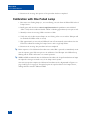
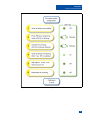
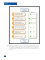
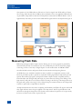
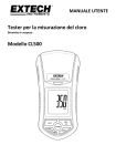
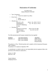
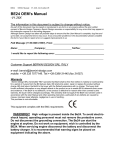
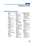
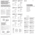
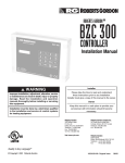
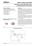
.
USER MANUAL
FLD-2
FAILED LAMP DETECTOR
Revised: January 15, 2010
M ICRO -A IDE C ORPORATION
Tel: 626-915-5502
Fax: 626-331-9484
685 Arrow Grand Circle Covina, CA 91722
E-mail: [email protected]
Copyright © 2009 by MICRO-AIDE Corporation
All rights reserved. No part of this document may be reproduced or transmitted in any form or by any means
without the written permission of MICRO-AIDE Corporation.
The information in this document is subject to change without notice. MICRO-AIDE believes the information
contained in this document to be accurate. However, MICRO-AIDE assumes no responsibility for any errors or
omissions.
TABLE OF CONTENTS
CHAPTER 1
GENERAL DESCRIPTION
Introduction . . . . . . .
Key Features . . . . . .
Comparing FLD-2 Versions
About this Manual . . . .
CHAPTER 2
CHAPTER 3
.
.
.
.
.
.
.
.
.
.
.
.
.
.
.
.
.
.
.
.
.
.
.
.
.
.
.
.
.
.
.
.
.
.
.
.
.
.
.
.
.
.
.
.
.
.
.
.
.
.
.
.
.
.
.
.
.
.
.
.
.
.
.
.
.
.
.
.
.
.
.
.
.
.
.
.
.
.
.
.
.
.
.
.
1
1
2
2
.
.
.
.
.
.
.
.
.
.
.
.
Introduction . . . . . . . . . . . .
Unpacking . . . . . . . . . . . .
Installation Procedure . . . . . . . .
Location . . . . . . . . . . .
Mounting . . . . . . . . . . .
Site Preparation . . . . . . . .
Peripheral Equipment . . . . . .
Cabling . . . . . . . . . . . .
Power. . . . . . . . . . .
Lamp Circuits. . . . . . . .
Input and Output Circuits . . .
Applying Power . . . . . . . .
Calibration Procedure . . . . . . . .
Switch Settings. . . . . . . . .
Calibration with All Lamps Flashing .
Calibration with One Failed Lamp .
.
.
.
.
.
.
.
.
.
.
.
.
.
.
.
.
.
.
.
.
.
.
.
.
.
.
.
.
.
.
.
.
.
.
.
.
.
.
.
.
.
.
.
.
.
.
.
.
.
.
.
.
.
.
.
.
.
.
.
.
.
.
.
.
.
.
.
.
.
.
.
.
.
.
.
.
.
.
.
.
.
.
.
.
.
.
.
.
.
.
.
.
.
.
.
.
.
.
.
.
.
.
.
.
.
.
.
.
.
.
.
.
.
.
.
.
.
.
.
.
.
.
.
.
.
.
.
.
.
.
.
.
.
.
.
.
.
.
.
.
.
.
.
.
.
.
.
.
.
.
.
.
.
.
.
.
.
.
.
.
.
.
.
.
.
.
.
.
.
.
.
.
.
.
.
.
.
.
.
.
.
.
.
.
.
.
.
.
.
.
.
.
.
.
.
.
.
.
.
.
.
.
.
.
.
.
.
.
.
.
.
.
.
.
.
.
.
.
.
.
.
.
.
.
.
.
.
.
.
.
.
.
.
.
.
.
.
.
.
.
.
.
.
.
.
.
.
.
.
.
.
.
.
.
.
.
.
.
.
.
.
.
.
.
.
.
.
.
.
.
.
.
.
.
.
.
.
.
.
.
.
.
.
.
.
.
.
.
.
.
.
.
.
.
.
.
.
.
.
.
.
.
.
.
.
.
.
.
.
.
.
.
.
.
.
.
.
.
.
.
3
3
3
5
5
5
5
6
6
6
6
6
7
7
7
8
.
.
.
.
.
.
.
.
.
.
.
.
.
.
.
.
.
.
.
.
.
.
.
.
.
.
.
.
.
.
.
.
.
.
.
.
.
.
.
.
.
.
.
.
.
.
.
.
.
.
.
.
.
.
.
.
.
.
.
.
.
.
.
.
.
.
.
.
.
.
.
.
.
.
.
.
.
.
.
.
.
.
.
.
.
.
.
.
.
.
.
.
.
.
.
. 11
. 11
. 11
. 11
. 12
INSTALLATION AND SETUP
OPERATION
Introduction . . . . . . .
How to Operate an FLD-2 .
Operating Modes . . .
Reporting Failed Lamps
Measuring Flash Rate .
CHAPTER 4
.
.
.
.
.
.
.
.
.
.
.
.
.
.
.
.
.
.
.
.
.
.
.
.
.
.
.
.
.
MAINTENANCE
Introduction . . . . . . . . . . . . . . . . . . . . . . . . . . . . . . . . 13
Replacing the Power Fuse . . . . . . . . . . . . . . . . . . . . . . . . . . 13
Trouble-shooting Guide . . . . . . . . . . . . . . . . . . . . . . . . . . . 14
APPENDIX A
TECHNICAL DATA
Specifications . . . . . . . . . . . . . . . . . . . . . . . . . . . . . . . 15
iii
TABLE OF CONTENTS
APPENDIX B BILLS OF MATERIAL
FLD-2 Bill of Material . . . . . . . . . . . . . . . . . . . . . . . . . . . . 17
FLD-2 Subassemblies . . . . . . . . . . . . . . . . . . . . . . . . . . 17
PA85-0142/00 Processor PCB . . . . . . . . . . . . . . . . . . . . . 17
iv
CHAPTER 1
GENERAL DESCRIPTION
Introduction
Since 1988 MICRO-AIDE has provided the rail signal industry with a broad range of event
recording and ancillary products. Our ancillary products include a variety of devices that, in many
cases, complement the use of our Event Recorders and Data Loggers. The Failed Lamp Detector
(referred to as the FLD-2) is one of these products.
The FLD-2 has been redesigned for use in a broader range of applications, including those where
an EOR relay is not available. More specifically, an FLD-2 can be used to detect lamp failures in
installations that utilize Safetran’s Solid State Crossing Controller (SSCC). However, compatibility
with relay-based flashing control systems has been retained.
Unlike other products, the FLD-2 will operate as a standalone device. Its outputs do not require
monitoring by the Analog Inputs of an Event Recorder. Its design incorporates non-intrusive
Hall-Effect circuitry to monitor AC and DC currents. It is able to independently monitor two
lamp circuits. Its four sensors allow for separate monitoring of the EB and EN circuit halves. The
FLD-2 will automatically report a single lamp failure. It does so by asserting its Light Out (LO)
output signal. The LO signal is fully compatible with the Digital Inputs of any Event Recorder or
RTU. Another unique aspect of the FLD-2 is its Flash Pulse (FP) output signal. The FP signal
pulses high and low as current is sensed in the EB and EN conductors. It too is compatible with
the Digital Inputs of any Event Recorder. In SSCC-based systems that lack an EOR relay, the FP
signal can be monitored by an Event Recorder (e.g., CWR-24E or CWR-72E). The recorder can
then be configured to report the precise flash rate and duty cycle of the lamp circuit.
The FLD-2 is also easy to install and operate. A simple calibration procedure allows the FLD-2 to
operate without further intervention. There are no recurring adjustments or alignment procedures
to perform after the initial calibration is completed. Its design is based upon the use of digital-toanalog conversion circuitry and is therefore not prone to drift. All of the calibration derived operating parameters are stored in non-volatile memory within the FLD-2.
Key Features
Listed below are some of the standard features included with every FLD-2.
• Single lamp failure detection for circuits with up to 12 lamps (nominal 25W lamps).
• Current sensing range is 7.5 to 30Adc ( 5 to 21Aac), incorporates true RMS sampling
algorithm.
1
MICRO-AIDE
FLD-2 USER MANUAL
• Compensation for halogen and incandescent lamp types is provided.
• Automatic compensation for variations in the DC power source is provided.
• Separate monitoring of the EB and EN conductors allows the FLD-2 to provide a Flash Pulse
output signal in systems that do not include an EOR relay.
• Complete isolation between the power terminals and lamp circuit conductors is insured by the
passive nature of the FLD-2 circuit.
• BN, chassis and XR inputs have an isolation rating in excess of 3800Vdc.
• Installation is quite simple. Input wires are terminated in detachable, tension clamp terminals.
Wire sizes as large as 12AWG can be used.
• Grommet lined holes in the FLD-2 are large enough to pass a standard sized .5" ring lug.
• Any BN battery source in the range of 10 to 36Vdc can power the detector.
Comparing FLD-2 Versions
In 2009 the FLD-2 was substantially redesigned. The major points of distinction between the
current and earlier models are listed below.
• The new design incorporates a total of four (as opposed to two) current sensors. This allows
the new design to separately monitor the EB and EN conductors.
• Since the new design separately monitors the EB and EN conductors, it is able to provide a
Flash Pulse (FP) output signal that toggles high and low when flashing is detected.
• Configuration and selection switches are directly accessible without the removal of any panel.
About this Manual
This document is intended to provide the user with comprehensive, easy-to-read instructions on
how to install, set up, operate and maintain the MICRO-AIDE FLD-2 Failed Lamp Detector.
Wherever possible, step-by-step instructions have been included. In the event the user has questions about any of the described procedures the user should contact MICRO-AIDE for
assistance. Additional copies of this manual are available upon request.
MICRO-AIDE CORPORATION
685 Arrow Grand Circle
Covina, CA 91722
Tel: 626-915-5502 Fax: 626-331-9484
E-mail: [email protected]
Note The MICRO-AIDE Material Return and Limited Warranty policies can be found on the inside
back cover of this manual.
2
CHAPTER 2
INSTALLATION AND SETUP
Introduction
This chapter describes how to properly unpack, install and set up the FLD-2 prior to operation. It
is advisable to review the Unpacking, Installation and Calibration sections before actually
performing the procedures described in this chapter.
Unpacking
Each FLD-2 is packed in a shipping carton that is properly sized for the product. Abundant
packing materials are provided to minimize mechanical shock to the contents. Before opening the
carton inspect it for damage. Damage to the carton should be noted. Carefully remove the
product. It is advisable to save all packing materials in the event the product ever needs to be
returned to MICRO-AIDE.
Inspect the product for visual damage. It should not be scratched, dented or deformed in any way.
If it appears the product was damaged in shipment the responsible carrier should be notified
immediately. MICRO-AIDE will assist the user in filing a claim in the event damage was sustained
during shipment.
Installation Procedure
The following sections describe the recommended Installation Procedure. Figure 1 and
Figure 2 on page 4 illustrate elements that are common to most installations. The illustrations
also depict the location of each connector used in the installation.
3
MICRO-AIDE
FLD-2 USER MANUAL
Figure 1 - Typical Installation - Top Panel View
Figure 2 - Typical Installation - Front Panel View
4
CHAPTER 2
INSTALLATION AND SETUP
Location
The location where the FLD-2 is to be installed should comply with a few simple requirements.
The ambient temperature near the detector should be in the range from -40ºC to 72ºC.
Mounting
The FLD-2 can be mounted on top of a suitable shelf or secured to a back board. Although the
FLD-2 utilizes magnetic field sensors, they are not affected by the earth’s magnetic field. Consequently, the detector can be mounted in either a vertical or horizontal orientation. It is advisable
to mount the FLD-2 away from large electric motors, machinery or conductors that might
generate substantial magnetic fields.
Site Preparation
The equipment location must have access to a stable 10 to 36Vdc power source. A pair of wires
must be run from the power source to the location where the detector will be mounted. The
FLD-2 wire ends must be stripped approximately 1/4". The stripped ends will be secured by
tension clamp terminals located along the front panel of the detector. One wire must be
connected to the positive voltage of the power source and the other wire must be attached to the
return of the power source. The tension clamp terminals will accept wire sizes as large as 12AWG.
The two wires must be properly secured to prevent damage.
The XR inputs and LO (Light Out) and FP (Flash Pulse) outputs use the same tension clamp
terminals as those required by the power leads. Each wire should be tagged with its circuit identity.
Each input cable or wire bundle should be secured to prevent damage to the connections at either
end.
Peripheral Equipment
The FLD-2 is designed to operate as a standalone device. It does not need to be connected to a
PC for either setup, calibration or operation. For reporting and logging purposes the FLD-2 LO
output can be connected to the Digital Inputs of an Event Recorder or RTU. In those installations
where an EOR relay is not available the user may wish to connect the FLD-2 FP output to a
Digital Input of an Event Recorder. This allows the Event Recorder to report flash rates and duty
cycles. Cable connections between the FLD-2 and an Event Recorder or RTU should be kept to
less than 20' in length.
5
MICRO-AIDE
FLD-2 USER MANUAL
Cabling
Follow the steps listed below to complete the cabling installation.
Tip The power, input and output wires all terminate in tension clamp connectors that are detachable.
The cable installation can be performed more easily if the female connectors are first detached
from their male halves that remain secured to the FLD-2 circuit board. Figure 3 illustrates the
proper use of the tension clamp lever.
Figure 3 - Tension Clamp Lever
Power
Ensure that the power is off at the power source. The two wires from the power source must be
secured to either pair of tension clamp terminals labeled “B” and “N”, respectively.
Lamp Circuits
The FLD-2 is designed to monitor current in both halves of a lamp circuit. As illustrated in
Figure 2 on page 4, the EB and EN conductors are passed through holes in the unit. The unit is
able to monitor a total of two lamp circuits. The FLD-2 performs an RMS conversion of the
current sensing samples it acquires. Consequently, the direction of current flow through the
FLD-2 is of no concern. The inside diameter of the protective grommet that lines each current
sensing hole is .56". It is large enough to pass a straight angle (inline) .5" ring lug.
Tip The EB and EN conductors can be passed through the unit either front-to-back or back-to-front.
Input and Output Circuits
The XR outputs and LO and FP outputs are each comprised of two polarity-sensitive conductors
identified as positive (+) and negative (-). These conductors must be wired to terminals with
matching polarities. The XR inputs are optically isolated from all other terminals. Each output
conductor includes a 1.5KOhm series limiting resistor.
Applying Power
Once the cabling is installed the power can be applied. The Power LED should illuminate whenever power is on. This completes the FLD-2 Installation Procedure. The Calibration Procedure
can now be started.
6
CHAPTER 2
INSTALLATION AND SETUP
Calibration Procedure
The FLD-2 must be calibrated against the operational characteristics of the crossing. The characteristics that impact the FLD-2 include the number of lamps, lamp type and source voltage. At the
conclusion of the Calibration Procedure data pertinent to these characteristics is stored in the
non-volatile memory of the FLD-2. If power is lost indefinitely to the entire crossing installation,
the FLD-2’s calibrated operation will be fully restored immediately after power is reapplied. The
FLD-2 can be calibrated and will operate properly in the presence of flashing rates in the range
of 35 to 65fpm.
Switch Settings
Before the Calibration Procedure can be started, the piano-style switch must be set in accordance
with the requirements of the crossing installation. The four-position switch is located along the
top panel of the FLD-2. A description of each switch setting is listed in Table 1.
Lamp Type
Voltage
SW-1/-2
SW-3
Halogen
DC
On / On
On
Incandescent
DC
Off / Off
On
Halogen
AC
On / On
Off
Incandescent
AC
Off / Off
Off
Table 1 - Switch Setting Configurations
Caution Position 4 of the piano switch must always be left in the on position.
Calibration with All Lamps Flashing
1. Verify that all of the lamps for Lamp Circuit 1 are installed.
2. Briefly press and then release a single time the pushbutton switch labeled “PB1”. Verify that
the indicator labeled “LED1” is blinking approximately once per second.
3. Manually activate the crossing. LED1 continues to blink.
4. Verify that all lamps are flashing properly. After one second the XR input will be validated and
LED1 will be on steady.
5. Wait approximately 10 seconds and LED1 will turn off automatically. This indicates that the
FLD-2 has calibrated a reading for Lamp Circuit 1 with all lamps on.
7
MICRO-AIDE
FLD-2 USER MANUAL
6. Deactivate the crossing. This portion of the procedure has been completed.
Calibration with One Failed Lamp
1. Disconnect two flashing lamps (i.e., not an end lamp), one each from the EB and EN halves of
Lamp Circuit 1.
2. Briefly press and then release twice in rapid succession the pushbutton switch labeled
“PB1”. Verify that the indicator labeled “LED1” is blinking approximately twice per second.
3. Manually activate the crossing. LED1 continues to blink.
4. Verify that only the disconnected lamps are not flashing. After one second the XR input will
be validated and LED1 will be on steady.
5. Wait approximately 10 seconds and LED1 will turn off automatically. This indicates that the
FLD-2 has calibrated a reading for Lamp Circuit 1 with a single lamp failure.
6. Deactivate the crossing. The procedure has been completed.
Tip Either sequence of the Calibration Procedure starts when PB1 is pressed. To immediately terminate the sequence, press PB1 once prior to the validation of the XR input. The LED will stop
blinking and the FLD-2 will return to its normal operation.
Tip MICRO-AIDE recommends that the Calibration Procedure also be performed whenever lamps
are replaced or changes are made to any of the lamp control systems.
The various steps that comprise the Calibration Procedure are also diagrammed in Figure 4 on
page 9 and Figure 5 on page 10. If required, repeat the steps listed above for Lamp Circuit 2,
making reference instead to PB2 and LED2.
8
CHAPTER 2
INSTALLATION AND SETUP
Figure 4 - Calibration Procedure - All Lamps Flashing
9
MICRO-AIDE
FLD-2 USER MANUAL
Figure 5 - Calibration Procedure - One Failed Lamp
Note If a problem arises during any portion of the Calibration Procedure the user should refer to the
section entitled “Trouble-shooting Guide” on page 14. If the problem remains unresolved, the
user should contact MICRO-AIDE customer service. Instructions on how to proceed will be
offered. Material Return and Limited Warranty policies are described on the inside back cover of
this manual.
10
CHAPTER 3
OPERATION
Introduction
This chapter describes how the FLD-2 can be used to detect failed lamps at a typical crossing
facility. Its use in conjunction with an Event Recorder or RTU is also described.
How to Operate an FLD-2
As described in detail in Chapter 2, the FLD-2 can be used in a variety of configurations. As a
standalone device, or as detector that operates as an element in a larger reporting system, its
design is flexible and versatile. The following sections describe the primary operational aspects of
the FLD-2. It is important to note that once installed and properly calibrated the FLD-2 operates
automatically. The user should have no further need to intervene in the operation of the detector.
Operating Modes
As listed in Table 1 on page 7, positions 1 and 2 of the piano switch are used to select either
halogen or incandescent lamps. The FLD-2 is designed to monitor nominal 25W lamps as used in
typical crossing facilities. The FLD-2 is able to compensate for changes in current flow as the
source voltage changes. However, the current-versus-voltage relationship typical of halogen lamps
is not shared by incandescent lamps. The FLD-2 utilizes the halogen/incandescent setting to
adjust the amount of compensation by lamp type.
Note Current-versus-voltage compensation only occurs when the FLD-2 is used in DC mode.
Reporting Failed Lamps
The Light Out (LO) signal is used by the FLD-2 to indicate that one or more lamps have failed in
either the EB or EN half of the applicable lamp circuit. The plus and minus outputs of both LO
signals are fully compatible with the Digital Inputs of any Event Recorder or RTU. The latter can
be used to log an event and/or dispatch a failure notice to a maintenance center.
The LO signal is asserted only while the failure is being detected. That is, if a lamp has failed the
FLD-2 will indicate the failure only while the crossing is active and the lamp circuit is drawing
current. Accordingly, the LO signal will return to its off state when the crossing is once again idle
and a failure will be indicated each time the crossing is active.
11
MICRO-AIDE
FLD-2 USER MANUAL
The operation of the LED indicators follow that of the LO signals. The LEDs will be off when
the crossing is idle. Shortly after the XR has been validated as active, the applicable LED will turn
on provided no lamp failure is detected. If a lamp failure is detected the LED will blink at a rate of
approximately four times per second. The LED and FP signal behaviors are depicted in Figure 6.
Figure 6 - LED and FP Behavior
Measuring Flash Rate
Railroad operating procedures require that the flashing rate of crossing signals be periodically
measured and reported. For installations that use an EOR relay this can be achieved by simply
connecting contacts of the relay to Digital Inputs of an Event Recorder. All MICRO-AIDE
recorders include extensive and precise flash rate measurement and reporting features.
An EOR relay is not available in installations where an SSCC (or comparable system) is used.
However, the FLD-2 is able to provide an equivalent flashing signal. Both lamp circuits provide
separate Flash Pulse (FP) signals. Their plus and minus outputs are fully compatible with any
Event Recorder. The FP signal will pulse high (on) when current is flowing in the EB leg of the
lamp circuit. It will pulse low (off) when current is flowing in the EN leg of the lamp circuit. The
FP signals will operate in the range of 35 to 65fpm. Except in extreme situations the FP signal will
continue to pulse while a lamp failure is detected.
An important distinction exists when comparing the EOR relay and FLD-2 FP signals. The EOR
relay signal indicates when voltage is applied to the lamp circuit. The FP signal indicates actual
current flow through the lamp circuit. The former cannot indicate the presence of an open circuit,
the latter can. Both can be used to report flash rate.
12
CHAPTER 4
MAINTENANCE
Introduction
The primary purpose of this chapter is to describe the recommended trouble-shooting methods
to be used with the FLD-2. It should be referred to if ever a questionable symptom arises during
the operation of the detector.
The FLD-2 is designed to provide its user with many years of trouble-free operation. There are no
user serviceable parts inside the detector. There are no consumable items or supplies that need to
be replaced or replenished. The user may occasionally need to wipe dust away from the external
surfaces of the detector. This should be done with a clean, dry cloth. The mechanical design of
the chassis provides the internal electronic assembly with a nearly sealed environment. Due to the
low power consumption of the detector ventilation holes are not required. The inside of the
detector should remain clean indefinitely. Additionally, MICRO-AIDE printed circuit boards
(PCBs) are sealed with a moisture and fungus resistant conformal coating.
Replacing the Power Fuse
The only reason the user would need to access the inside of the FLD-2 is to check and/or replace
the power fuse. Figure 1 on page 4 provides an illustration of the detector’s front panel. To
replace the power fuse follow the steps listed below.
1. Remove power by detaching the connector labeled “Power” located along the front panel of
the detector.
2. Remove all of the input and output connectors.
3. With both lamp circuits de-energized, remove both sets of the EB and EN conductors.
4. Remove the detector from the equipment shelf or backboard.
5. Remove two 6-32 1/4" screws from each of the front and back panels of the top sheetmetal
assembly. The screws in question are located near the horizontal center line of the detector and
are nearest the left and right edges.
Caution
Do not remove any of the other four screws located on the rear panel. They are used to secure
the internal PCB to the top sheetmetal assembly.
6. The power fuse is rated at 1A and conforms to the 2AG size standard. Before replacing the
fuse the cause of the blown fuse should be ascertained and cleared if possible.
13
MICRO-AIDE
FLD-2 USER MANUAL
7. After replacing the fuse reassemble the detector by performing the previous steps in reverse
order.
Caution Electrostatic discharges can cause serious damage to electronic components. When handling
circuitry inside the detector it is recommended that the user wear a wrist grounding strap.
Trouble-shooting Guide
The following guide is provided to assist the user in resolving problems that may occur with the
operation of the FLD-2. It can be especially helpful when attempting to operate the detector for
the first time. Where multiple steps are indicated it is recommended that they be performed in the
order listed.
If the user is unable to resolve the problem, MICRO-AIDE customer service technicians should
be contacted. The user will be asked to state the problem, related symptoms, and indicate any
operations or conditions that have a bearing on the problem. If available, the results of any diagnostic tests should be reported.
Symptom or Problem
Resolution
No indication of power
Verify 10 to 36Vdc at B and N power terminals
Inspect fuse on internal PCB, refer to the procedure
entitled “Replacing the Power Fuse” on page 13
LED does not blink when PB is pressed
Contact MICRO-AIDE for assistance
After starting calibration LED does not
stop blinking
Verify XR is activated
Verify XR + and - inputs are properly connected
LO signal does not report lamp failure(s)
Verify LED blinks at high rate when failure occurs; if not,
perform both calibration procedures again, making sure
one lamp is removed from EB and EN circuits
Verify all lamps are nominal 25W
Verify proper switch settings at FLD-2
Verify lamp voltage source is within range
Verify LO + and - outputs are connected properly
Verify Lamp Circuit1(2) is monitoring the correct EB1(2)
and EN1(2) conductors
FP output is not reporting proper flash rate
Verify FP + and - outputs are connected properly
Verify Event Recorder detection times are set correctly
for expected flash rate
Verify Event Recorder is enabled for flash reporting
Table 2 - Guide to Trouble-shooting Techniques
This completes the User Manual for the FLD-2. As an aid to the user two appendices have been
provided. They include detailed specifications and a complete Bill of Materials.
Any comments the reader may have on how to improve this manual are welcomed. Comments
should be forwarded to the Director of Marketing, MICRO-AIDE Corporation.
14
APPENDIX A
TECHNICAL
DATA
Specifications
Physical
Size
Length: 7.0"
Height: 3.4"
Depth: 2.5"
Weight
14oz.
Environmental
Storage
Temperature: -50ºC to 85ºC
Humidity: 0 to 95%, noncondensing
Operating
Temperature: -40ºC to 72ºC
Humidity: 0 to 95%, noncondensing
Mounting
Shelf or back board mounting
Construction
Chassis
Fully enclosed, anodized
aluminum
Externally accessible switches,
LEDs and connectors
Electrical
All components mounted on
conformal coated, internal PCB
Power
Voltage
Range: 10 to 36Vdc
Consumption
Typical: 1W
Non-volatile memory
Saves all calibration parameters
Parameters are auto-restored
when power is reapplied
Isolation
Power
Minimum: 3800Vdc from B and
N terminals to chassis and inputs
Lamp Circuit Inputs
Minimum: 5000Vdc to chassis or
any terminal
Inputs
Input Impedance
Lamp Circuits: infinite, uses
Hall-effect circuitry for complete
isolation
XR: minimum 10KOhms, optoisolated
Range
Lamp Circuits: 7.5 to 30Adc (5
to 21Aac), per EB and EN circuit
with lamps illuminated
XR Input - On: 5 to 40Vdc
XR Input - Off: 0 to 2Vdc
Flashing: 35 to 65fpm
Capacities
Inputs
Connectors
Inputs and Outputs
Total 3, detachable, tension
clamp, 4 terminals, 12 to 22AWG
Power
Single, detachable, tension
clamp, 4-terminals, 12 to 22AWG
Dual B and N terminals
Controls
Pushbutton Switches
Quantity: Total 2, 1 per lamp
circuit
Usage: initiates calibration
procedure
Piano Switch
Quantity: 1 with 4 positions
Positions 1, 2: selects halogen
or incandescent lamps
Position 3: enables compensation for DC voltage fluctuation
Position 4: always on, for factory
use only
LED Indicators (3)
Lamp Circuits: 2, fully independent, AC or DC
Power
Separate sensors for all EB and
EN conductors
Lamp Circuit 1 and 2
3 to 12 lamps per EB and EN
circuit, 25W per lamp nominal
XR: 2 total, 1 per lamp circuit,
± pair
Outputs
Light Out: 2 total, 1 per lamp
circuit, ± pair, 3 to 12mAdc
Flash Pulse: 2 total, 1 per lamp
circuit, ± pair, 3 to 12mAdc
Pulses high and low with current
flow
Range is 35 to 65fpm
Green, illuminates with power
Green, flashes at various rates
Off: crossing is idle
On: crossing is active, no light
failures
Slow / Medium Flashing:
indicates calibration state
Fast Flashing: crossing is active,
light failure detected
MICRO-AIDE reserves the right
to make changes, at its sole
discretion, to any specifications
listed herein.
15
MICRO-AIDE
FLD-2 USER MANUAL
User Notes
16
APPENDIX B
BILLS OF MATERIAL
FLD-2 Bill of Material
M-A Part No.
Description / MFG Part No.
.
.
.
.
.
.
.
.
.
. Qty.
PA85-0142/00
PCB ASSEMBLY, PROCESSOR
.
.
.
.
.
.
.
.
.
.
.
1
H 8477/00
GROMMET, .75" I.D.
KEYSTONE: 8477
.
.
.
.
.
.
.
.
.
.
.
.
8
JH231-131/00
LEVER, CONNECTOR, TENSION CLAMP
WAGO: 231-131 .
.
.
.
.
.
.
.
.
.
.
.
.
.
2
JW170748/00
CONNECTOR, TENSION CLAMP, FEMALE, 4-POSITION
WEIDMULLER: 1707480000
.
.
.
.
.
.
.
.
.
.
.
4
M 220449/00
SHEETMETAL, BOTTOM
.
.
.
.
.
.
.
.
.
.
.
.
1
M 220450/00
SHEETMETAL, TOP
.
.
.
.
.
.
.
.
.
.
.
.
1
ZMFLD-2
USER MANUAL, FLD-2
.
.
.
.
.
.
.
.
.
.
.
.
1
.
.
FLD-2 Subassemblies
PA85-0142/00 Processor PCB
M-A Part No.
Description / MFG Part No.
.
.
.
.
.
.
.
.
.
. Qty.
P 85-0142/00
PCB, PROCESSOR, FLD-2 .
.
.
.
.
.
.
.
.
.
.
1
C .1MF/00
CAPACITOR, .1MF, 50V, CERAMIC .
.
.
.
.
.
.
.
.
.
7
CE100MF/00
CAPACITOR, 100MF, 25V, AXIAL, ELECTROLYTIC
NICHICON: TVX1E101MAA .
.
.
.
.
.
.
.
.
.
.
.
1
CE220MF/00
CAPACITOR, 220MF, 50V, AXIAL, ELECTROLYTIC
NICHICON: TVX1H221MCA .
.
.
.
.
.
.
.
.
.
.
.
1
D 1N4004/00
DIODE, 400V
1N4004
.
.
.
.
.
.
.
.
.
.
.
.
3
D 1N5819/00
DIODE, SCHOTTKY, 40V, 1AMP
1N5819
.
.
.
.
.
.
.
.
.
.
.
.
.
.
.
1
DL3962-01/00
LED, GREEN, RIGHT ANGLE
HP: HLMP-3962-010 .
.
.
.
.
.
.
.
.
.
.
.
.
3
F 225001/00
FUSE, 1 AMP
LITTELFUSE: 225001
.
.
.
.
.
.
.
.
.
.
.
.
1
FH111501/00
FUSE CLIP
LITTELFUSE: 111501
.
.
.
.
.
.
.
.
.
.
.
.
2
H PTX2515/00
TOROID, .062" GAP
EASTERN COMPONENTS: P-TX251510-3C81-G.062 .
.
.
.
.
.
.
4
H TP-101/00
TEST POINT
COMPONENTS CORP.: TP-101-10
.
.
.
.
.
.
3
.
.
.
.
.
.
.
.
17
MICRO-AIDE
CWR-72E USER MANUAL
18
M-A Part No.
Description / MFG Part No.
.
.
.
.
.
.
.
.
.
. Qty.
JRICO-143/00
SOCKET, IC, 14-PIN
OUPIIN: 8003-14T3 .
.
.
.
.
.
.
.
.
.
.
2
JW151366/00
CONNECTOR, MALE, 12-POSITION, RIGHT ANGLE
WEIDMULLER: 1513660000
.
.
.
.
.
.
.
.
.
.
.
1
JW152206/00
CONNECTOR, MALE, 4-POSITION, STRAIGHT
WEIDMULLER: 1522060000
.
.
.
.
.
.
.
.
.
.
.
1
L 20-102K/00
CHOKE, 1000UH
ALLIED ELECTRONICS: APC20-102K
.
.
.
.
.
.
.
.
.
1
Q A1323/00
TRANSISTOR, HALL-EFFECT
ALLEGRO: A1323EUA-T
.
.
.
.
.
.
.
.
.
.
.
.
4
Q PN2222A/00
TRANSISTOR, TO-92
PN2222
.
.
.
.
.
.
.
.
.
.
.
.
.
.
4
QRLM2574N/01
VOLTAGE REGULATOR, 5.0V, DIP
NATIONAL: LM2574N-5
.
.
.
.
.
.
.
.
.
.
.
.
1
R 470 OHM/00
RESISTOR, 470 OHM, 5%, .25W
.
.
.
.
.
.
.
.
.
.
3
.
.
.
R 1K/03
RESISTOR, 1K, 1%, .25W
.
.
.
.
.
.
.
.
.
.
.
7
R 1.5K/00
RESISTOR, 1.5K, 5%, .25W
.
.
.
.
.
.
.
.
.
.
.
8
R 4.7K/01
RESISTOR, 4.7K, 5%, .25W
.
.
.
.
.
.
.
.
.
.
.
4
R 3.01K/00
RESISTOR, 3.01K, 1%, .25W .
.
.
.
.
.
.
.
.
.
.
4
R 6.34K/00
RESISTOR, 6.34K, 1%, .25W .
.
.
.
.
.
.
.
.
.
.
1
R 10K/00
RESISTOR, 10K, 5%, .25W
.
.
.
.
.
.
.
.
.
.
2
SD4PIANO/00
SWITCH, 4-POSITION, PIANO, DIP
CTS: 195-4MST .
.
.
.
.
.
.
.
.
.
.
.
.
.
1
SHB32-101/00
SWITCH, CAP, BLACK
OMRON: B32-1010
.
.
.
.
.
.
.
.
.
.
.
.
.
2
SPB3F3152/00
SWITCH, PUSHBUTTON
OMRON: B3F-3152
.
.
.
.
.
.
.
.
.
.
.
.
.
2
U 16F883/00
IC, PIC PROCESSOR, DIP
MICROCHIP: PIC16F833-I/SP .
.
.
.
.
.
.
.
.
.
.
1
ULOP490GP/00
IC, OP-AMP, QUAD, DIP
ANALOG DEVICES: OP490GP
.
.
.
.
.
.
.
.
.
.
.
1
UOPC815/00
IC, OPTOCOUPLER, DIP
SHARP: PC815 .
.
.
.
.
.
.
.
.
.
.
.
.
2
.
.
Material Return Policy
In the event the customer identifies a malfunction in any product, call or write MICRO-AIDE and obtain a
Return Material Authorization (RMA) number from the customer service department. Return the product to
MICRO-AIDE, freight prepaid, with a note (in-warranty repair) or a purchase order (out-of-warranty) for the
repair listing the following information:
• RMA number from MICRO-AIDE
• Return shipment address
• Name and telephone number of person familiar with the problem
• Brief description of the problem (include any printouts that may have a bearing on the problem)
• Method of payment for repair costs (out-of-warranty)
• Send product to the following address:
MICRO-AIDE CORPORATION
685 Arrow Grand Circle
Covina, CA 91722
Tel: 626-915-5502 Fax: 626-331-9484
E-mail: [email protected]
Limited Warranty
MICRO-AIDE warrants its products to be free from defects in material and workmanship for a period of
five (5) years from the date of shipment. This warranty is in lieu of any other warranty, expressed or implied. In
no event shall MICRO-AIDE be held liable for incidental or consequential damage resulting from (1) the use
of any of its products, or (2) any alleged breach of this warranty provision. MICRO-AIDE’s liability shall be
limited to repairing or replacing, at its sole discretion, any defective product which is returned in accordance
with the MICRO-AIDE Material Return Policy.
Product that has been subjected to abuse, misuse, alteration, accident, lightning damage, neglect or unauthorized installation or repair shall not be covered by this warranty. MICRO-AIDE reserves the right to make a
final decision as to the existence of any failures and the cause of such failures. No warranty is made with
respect to custom equipment or products produced to buyer’s specifications except as mutually agreed upon in
writing.
MICRO-AIDE CORPORATION
685 Arrow Grand Circle
Covina, CA 91722
Tel: 626-915-5502 Fax: 626-331-9484
E-mail: [email protected]