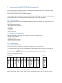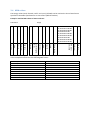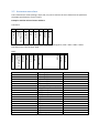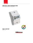
1
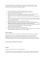
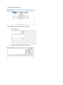
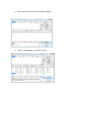
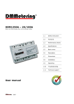
Installing and reading out a PRO370D M-bus meter 1 2 Safety instructions ........................................................................................................................... 3 1.1 Needed: ................................................................................................................................... 6 1.2 Read out software ................................................................................................................... 6 Inepro metering PRO370D M-Bus appendix ................................................................................. 10 2.1 General notes: ....................................................................................................................... 10 2.2 Supported commands: .......................................................................................................... 10 2.3 Addressing: ............................................................................................................................ 10 2.4 kWh values ............................................................................................................................ 11 2.5 Instantaneous values ............................................................................................................. 12 2.6 Baud rate ............................................................................................................................... 13 1 Safety instructions Information for your own safety This manual does not contain all of the safety measures for operation of this meter because special operating conditions, local code requirements or local regulations may necessitate further measures. However, it does contain information which must be adhered to for your own personal safety and to avoid material damage. This information is highlighted by a warning triangle with an exclamation mark or a lightning bolt depending on the degree of actual or potential danger: Warning This means that failure to observe the instruction can result in death, serious injury or considerable material damage. Caution This means hazard of electric shock and failure to take the necessary safety precautions will result in death, serious injury or considerable material damage. Qualified personnel Installation and operation of the device described in this manual may only be performed by qualified personnel. Only people that are authorized to install, connect and use this device, who have the proper knowledge about labeling and grounding electrical equipment and circuits and can do so in accordance with local (safety) regulations, are considered qualified personnel in this manual. Use for the intended purpose This device may only be used for the application cases specified in the catalog and the user manual and only in connection with devices and components recommended and approved by Inepro Metering B.V. Proper handling The prerequisites for perfect, reliable operation of the product are proper transport, storage, installation and connection, as well as proper operation and maintenance. During its operation certain parts of the meter might carry dangerous voltages. Only use insulated tools suitable for the voltages this meter is used for. Do not connect while the circuit is connected to a power or current source Only place the meter in a dry environment Do not mount the meter in an explosive area or exposed to dust, mildew and/or insects. Make sure the used wires are suitable for the maximum current of this meter. Make sure the AC wires are connected correctly before activating the current/voltage to the meter. Do not touch the meter’s connection clamps directly with your bare hands, with metal, blank wire or other conducting material as you will risk an electric shock that could cause possible injury, serious injury or death. Make sure the protection covers are replaced after installation. Maintenance and repair of the meter should only be carried out by qualified personnel. Never break any seals (if present on this meter) to open the front cover as this might influence the functionality or accuracy of the meter, and will void all warranty. Do not drop, or allow physical impact to the meter as there are high precision components inside that may break and affect the meter measurement negatively. All clamps should be properly tightened. Make sure the wires fit properly in the connection clamps. If the wires are too thin it will cause a bad contact which can spark causing damage to the meter and its surroundings. Exclusion of liability We have checked the contents of this manual and every effort has been made to ensure that the descriptions are as accurate as possible. However, deviations from the description cannot be completely ruled out, so that no liability can be accepted for any errors or omissions in the information given. The data in this manual are checked regularly and the necessary corrections will be included in subsequent editions. If you have any suggestions, please do not hesitate to contact us. Subject to technical modifications without notice. Copyright Copyright Inepro Metering June 2011. All rights Reserved. It is prohibited to pass on or copy this document or to use or disclose its contents without express permission of Inepro Metering BV. Any duplication is a violation of the law and subject to criminal and civil penalties. All rights reserved, particularly for pending or approved patent awards or registered trademarks. Registered trademarks DMMetering® is a registered trademark of Inepro Metering BV – member of the Inepro Group. Other names appearing in this manual may be trademarks of third parties and are property of their respectful owners. 1.1 Needed Mbus Converter (for example relay.de) Computer Inepro PRO370D M-bus meter Inepro read out software 1. Connect all the L1,L2,L3 and N wires to the Inepro meter according to the connection diagram: 2. Connect the Mbus communication wires between the converter and the meter (in this case terminal 26 and 27) 3. Connect the converter to the computer. 4. Turn on the power to the meter. 1.2 Read out software You can download the read out software, MBSheet, which we will use as an example: here. (if the link is not working just go to: www.relay.de -> downloads -> MBSheet). There might be other read out software available on the internet, but we often hear that our clients use this software, that is why we use this software as an example. Press the English flag Press Download Press Software (British flag) Select MBSheet, download it and press Execute 1. Open MBSheet 2. Select the right COM-port and baud rate. 3. Click “Search id” to start searching for meters 4. Click on read M-Bus to read the meters. 2 Inepro metering PRO370D M-Bus appendix This is an appendix to the M-Bus protocol describing how the PRO M-Bus meter should be read via M-Bus via a transparent wired converter. This document applies only to the PRO370D M-Bus. The PRO370D M-Bus supports both primary and secondary addressing, this document only addresses primary addressing, for secondary addressing please refer to the m-bus standards. 2.1 General notes: The meter communicates via the standardized M-Bus protocol and cabling. See www.m-bus.com or EN 13757-3. The serial communication is: - 300/2400(default)/9600 baud - 8 databits - Even parity - 1 stopbit - M-Bus Checksum 2.2 Supported commands: The following M-Bus commands are supported by the Inepro M-Bus meters. - Change primary address. - Change baudrate. - Read measurement values. - Read instantaneous values. 2.3 Addressing: The meter by default has ID 0. This can be set from 1-250, giving a maximum of 250 meters on the same bus. To (re)program the meter ID press the PRG button (middle button) on the meter, this will light up the unlocked icon ( ) and allow for programming commands to be processed. Example: changing the ID to 10. Command Reply 68 53 FE 51 27 16 E5 Acknowledge Stop byte 0A Checksum CI Field Broadcast C Field Start byte Packetlength (2 times) Start byte 01 7A New meter ID 06 06 Set primary address 68 The checksum is calculated by adding up all bytes from the C Field to the Checkum: 0x53 + 0xFE + 0x51 + 0x01 + 0x7A + 0x0A = 0x227, so checksum is 0x27, only the last byte is used. 2.4 kWh values The energy values (total, forward, tariff 1 and 2, etc) (all kWh) can be read via the short frame format specified in the M-Bus specifications as Class 2 Data (default readout). Example: read the kWh values of meter with ID 1 Command Reply Checksum Stop byte Start bye Packetlength (2 times) Start byte C Field 72 … 0C 04 92 02 00 00 8C 10 04 92 02 00 00 8C 20 04 00 00 00 00 0C 04 09 03 00 00 8C 10 04 09 03 00 00 8C 20 04 00 00 00 00 0C 04 97 00 00 00 8C 10 04 97 00 00 00 8C 20 04 00 00 00 00 xx 16 Stop byte Start byte 01 Checksum 08 kWh values BCD coded 68 12 byte header 4B 4B CI Field 68 Meter ID 16 Meter ID 5C C Field 10 5B 01 Checksum is last 2 bytes of the C Field plus the ID, 0x5B + 0x01 = 0x5C In this example the meter has the following kWh values: Total Total tariff 1 Total tariff 2 Total forward Forward tariff 1 Forward tariff 2 Total reverse Reverse tariff 1 Reverse tariff 2 2.92 kWh 2.92 kWh 0 kWh 3.09 kWh 2.09 kWh 0 kWh 0.97 kWh 0.97 kWh 0 kWh 2.5 Instantaneous values The instantaneous values (voltage, amps, kW, etc) can be read via the short frame format specified in the M-Bus specifications as Class 1 Data. Example: read the values of meter with ID 1 Command 68 53 01 B1 CI Field Meter ID C Field Start byte Packetlength (2 times) Start byte 05 16 Stop byte 03 03 Checksum 68 Checksum is last the bytes after the 2nd start byte counted together, 0x53 + 0x01 + 0xB1 = 0x105 Checksum byte is the last byte: 0x05. Start bye Start byte C Field Meter ID CI Field … 101 bytes data xx 16 Stop byte 72 Checksum 01 Values 08 12 byte header 68 Packetlength (2 times) Reply 68 74 74 In this example the meter has the following kWh values in the 101 byes data: 0B FD 47 34 45 02 0B FD 47 47 45 02 0B FD 47 00 00 00 0B FD 59 00 00 00 0B FD 59 00 00 00 0B FD 59 00 00 00 0B 2A 00 00 00 0B 2A 00 00 00 0B 2A 00 00 00 0B 2A 00 00 00 0B 2A 00 00 00 0B 2A 00 00 00 0B 2A 00 00 00 0B 2A 00 00 00 0A FD 3A 00 10 0A FD 3A 00 10 0A FD 3A 00 10 0A FD 3A 00 00 0A FD 3A 98 49 L1 Voltage (V) L2 Voltage (V) L3 Voltage (V) L1 Current (A) L2 Current (A) L3 Current (A) Total apparent power (kW) L1 apparent power kW L2 apparent power kW L3 apparent power kW Total power (kW) L1 power kW L2 power kW L3 power kW Total power factor L1 power factor L2 power factor L3 power factor Frequency (Hz) 245.34 V 245.47 V 0V 0A 0A 0A 0 kW 0 kW 0 kW 0 kW 0 kW 0 kW 0 kW 0 kW 1 1 1 0 49.98 Hz 2.6 Baud rate The baudrate of the meter is changed using the control frame format of the M-Bus specifications. Baud Rate (0xF800) CI Field 0xB8 0xBB 0xBD Baudra te 300 2400 9600 Example: changing baudrate to 9600 baud for all connected meters. 68 03 03 68 53 FE BD 0E 16 E5 Acknowledge Stop byte Checksum CI Field Broadcast C Field Start byte Packetlength (2 times) Start byte The checksum is calculated by adding up all bytes from the C Field to the Checkum: 0x53 + 0xFE + 0xBD = 20E, only the last byte is used to the checksum is 0x0E Note, for larger distances or large numbers of meters it is advised to choose a lower baudrate.