1
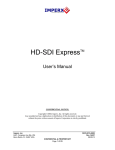
AN-795 APPLICATION NOTE One Technology Way • P.O. Box 9106 • Norwood, MA 02062-9106 • Tel: 781/329-4700 • Fax: 781/461-3113 • www.analog.com AD9880 Color Space Converter User’s Guide by Del Jones COLOR SPACE CONVERSION MATRIX The color space conversion matrix (CSC) in the AD9880 is a 3 3 matrix with full programmability of all coefficients in the matrix. Each coefficient is 12 bits wide to ensure that signal integrity is maintained. The CSC is designed to run at speeds of up to 150 MHz supporting 1080 p @ 60 Hz rates. With the “any-to-any” color space support, formats such as RGB, YUV, YCrCb, and others are supported by the CSC. The CSC contains three identical processing channels, one of which is shown in Figure 1. The main inputs, In_A, In_B, and In_C, come from 8-bit outputs of each ADC or DVI channel. Each input to the individual channels to the CSC is multiplied by a separate coefficient for each channel. In Figure 1 these coefficients are marked A1, A2, and A3. The variable in the figure labelled A4 is used as an offset control for Channel A in the CSC. The functional diagram for a single channel in the CSC is repeated for the other two remaining Channels B and C. The coefficients for these channels are called B1, B2, B3, B4, C1, C2, C3, and C4. �������� ���������� � �������� � � � �������������� �� � �� � � �������� ���������� � �������� ���������� � Figure 1. Single CSC Channel The coefficients are detailed in Table I with their default I2C power-on reset values. Table I. CSC Coefficients REV. 0 ����������� Bit AD9880 Register Default Value Description CSC_scale[1:0] 0x35 bits 6:5 1 Scaling for CSC formula A1[12:0] A2[12:0] A3[12:0] 0x35 – 0x36 0x37 – 0x39 0x39 – 0x3A 3154 2048 0 Coefficients for Channel A B1[12:0] B2[12:0] B3[12:0] 0x3D – 0x3E 0x3F – 0x40 0x41 – 0x42 –940 2048 –375 Coefficients for Channel B C1[12:0] C2[12:0] C3[12:0] 0x45 – 0x46 0x47 – 0x48 0x49 – 0x4A 0 2048 3719 Coefficients for Channel C A4[12:0] B4[12:0] C4[12:0] 0x3B – 0x3C 0x43 – 0x44 0x4B – 0x4C –1577 658 –1859 Offsets for the three channels AN-795 PROGRAMMING THE CSC The equations performed by the CSC are as follows: Programming Steps To arrive at programming values from typical formulas, the following steps must be performed: CSC Channel A Out_A = [In_A × 1. Check the value of each coefficient. A1 A2 A3 +B + In_C × + A 4] × 2CSC_scale 4096 4096 4096 (1) The coefficients can only be programmed in the range of [–0.999... +0.999]. To support larger coefficients, the CSC_scale function should be used (see Table II). (2) Determine the setting for CSC_scale and adjust coefficients (if necessary). CSC Channel B Out_B = [In_A × B1 B2 B3 +B + In_C × + B 4] × 2CSC_scale 4096 4096 4096 CSC Channel C Out_C = [In_A × C1 C2 C3 +B + In_C × + C 4] × 2CSC_scale 4096 4096 4096 2. Program the coefficient values. (3) Convert the float point coefficients into 12-bit fixed decimal format by multiplying them by [4096 / 2 CSC_scale ]. Convert into binary format, using twos complement for negative values. As Equations 1, 2, and 3 show, the A1 – A3, B1 – B3, and C1 – C3 coefficients are used to scale the primary inputs. The values of A4, B4, and C4 are then added as offsets. The CSC_scale bits allow the user to implement conversion formulas in which the conversion coefficients are 1. In other words, if an equation is being implemented whose coefficients are 1, the CSC_scale bits can be used to ensure that the resulting output code does not exceed the 12-bit limit of 4095. Table II describes the conditions under which each CSC_scale setting should be used. Note that if any coefficient in any of the three CSC equations requires scaling (CSC_scale 0), then all coefficients, including the offset values, are scaled as indicated by Equations 1, 2, and 3. The values of A1 – A4, B1 – B4 , and C1 – C4 will equal the coefficients from the desired conversion formula multiplied by 4096/ 2CSC_scale. Program A1 – A3, B1 – B3, and C1 – C3 3. Progam the offset values. Depending on the type of color space, conversion offsets may have to be used. Program A4, B4, and C4. CSC EXAMPLE The following sets of equations give an example of a conversion from an HDTV YCbCr to RGB (12 bits): R = Y + 1.540(Cr – 2048) = Y + 1.540 Cr – 3154 G = Y – 0.459(Cr – 2048) – 0.183(Cb – 2048) = Y – 0.459 Cr – 0.183 Cb + 1315 B = Y + 1.816(Cb – 2048) = Y + 1.816 Cb – 3719 Table II. CSC_scale Settings CSC_scale Conversion Coefficient 0 1 2 N<1 1N<2 2N<4 The original equations give offset values of 128 for the Pr and Pb components. The value of 128 equates to half the range on an 8-bit system. It must be noted that the CSC of the AD9880 operates on a 12-bit range. The offsets therefore must be changed from 128 to half the range of a 12-bit system, which is 2048. Note that for the CSC to operate properly, the channel mapping shown in Table III must be followed. Check the Value of Each Coefficient The maximum value for each coefficient on its own can only be within the range of –4095/4096 to 4095/4096 which equals [–0.999755859375 .. 0.999755859375]. Values outside this range do not fit into the 12-bit fixed point format used to program the coefficients. Table III. CSC Port Mapping Channel AD9980 Input (analog) CSC Channel Red/Pr Green/Y Blue/Pb RAIN GAIN BAIN A B C If the value of one or more coefficients exceeds the supported coefficient range, the CSC needs to be scaled using the CSC_scale bits. Output mapping depends on the output format. Refer to the AD9880 data sheet for details. With the CSC_scale set to “1,” all coefficients must be scaled by half, which makes them fit into the given coefficient range. The overall outputs of the CSC are then increased by a fixed value of two, thus compensating for the scaled down coefficients. –2– REV. 0 AN-795 In the example, the biggest coefficient is 1.816, so the CSC_scale bits would be set to “01.” • The coefficient values are programmed with 12-bit accuracy in a fixed point format. 1. To achieve a coefficient value of 1.0 for any given coefficient, the CSC_scale bits should be set to “1” and the coefficient should actually be programmed to a value of 0.5. Otherwise the largest value would be 4095/4096 = 0.9997, which is not exactly 1. While this value could be interpreted as a 1, it is recommended to use the value of 0.5 and the CSC_scale bit for maximum accuracy. • To translate the float point coefficients, they must be multiplied by 212 (4096) and then rounded to 12 bits. • Twos complement notation should be used for negative numbers. In_A carries the Pr or R components, In_B contains the Y or G components, and In_C delivers the Pb or B components. Similarly, Out_A = Pr or R, Out_B + Y or G, and Out_C = Pb or B. 2. For very large coefficient values (e.g., 2.58), the CSC_scale must be set to “2” and all coefficients must be scaled by one-quarter, which makes them fit into the given coefficient range. The overall outputs of the CSC are then gained up by a fixed value of four, thus compensating for the scaled down coefficients. Program the Offset Values When programming the offset values (A4, B4, C4) the CSC_scale is set to 1 so the offset value from the original equation must be divided by 2. Program the coefficient values as follows: Table IV. Example Offset Values R = 1.540 Cr + 0 Cb + 1 Y – 3154 G = –0459 Cr – 0.183 Cb + 1 Y + 1315 B = 0 Cr + 1.816 Cb + 1 Y – 3719 Equation Original Offset Adjusted Offset* Register Hex Value (13-bit, twos complement) Red Green Blue –3154 1315 –3719 –1577 657 –1859 A4[12:0] B4[12:0] C4[12:0] 0x19D7 0x0291 0x18BD *Since the CSC_scale is set to 1, the calculated coefficient is divided by 2 (2CSC_scale). Table V. Example Coefficient Calculations Equation Coefficients Calculation* Rounded Result (–4096 N 4096) Register Hex Value (Twos complement) Red Cr Y Cb 1.54 1 0 1.54 4096/2 1 4096/2 0 4096/2 3154 2048 0 A1[12:0] A2[12:0] A3[12:0] 0x0C52 0x0800 0x0000 Green Cr Y Cb –0.459 1 –0.183 0.459 4096/2 1 4096/2 0.183 4096/2 –940 2048 –375 B1[12:0] B2[12:0] B3[12:0] 0x1C54 0x0800 0x3E89 Blue Cr Y Cb 0 1 1.816 0 4096/2 1 4096/2 1.816 4096/2 0 2048 3719 C1[12:0] C2[12:0] C3[12:0] 0x000 0x0800 0x0E87 Equation *Since the CSC_scale is set to 1, the calculated coefficient is divided by 2. REV. 0 –3– AN-795 REGISTER SETTINGS FOR CSC EXAMPLE For the CSC example, the I2C registers of the AD9880 must be programmed with the values shown in Table VI. Table VI. Color Space Conversion and Decimation Filters Register Address Bit Description and Values Red/Cr Coeff. 1 0x35 unused * CSC_scale[1:0] 0 1 A1.12 0 A1.11 1 A1.10 1 A1.9 0 A1.8 0 0x0C 0x36 A1.7 0 A1.6 1 A1.5 0 A1.4 1 A1.3 0 A1.2 0 A1.1 1 A1.0 0 0x52 0x37 unused * unused * unused * A2.12 0 A2.11 0 A2.10 0 A2.9 0 A2.8 0 0x08 0x38 A2.7 0 A2.6 0 A2.5 0 A2.4 0 A2.3 0 A2.2 0 A2.1 0 A2.0 0 0x00 0x39 unused * unused * unused * A3.12 0 A3.11 0 A3.10 0 A3.9 0 A3.8 0 0x00 0x3A A3.7 * A3.6 * A3.5 * A3.4 0 A3.3 0 A3.2 0 A3.1 0 A3.0 0 0x00 0x3B unused * unused * unused * A4.12 1 A4.11 1 A4.10 0 A4.9 0 A4.8 1 0x19 0x3C A4.7 1 A4.6 1 A4.5 0 A4.4 1 A4.3 0 A4.2 1 A4.1 1 A4.0 1 0xD7 0x3D unused * unused * unused * B1.12 1 B1.11 1 B1.10 1 B1.9 0 B1.8 0 0x1C 0x3E B1.7 0 B1.6 1 B1.5 0 B1.4 1 B1.3 0 B1.2 1 B1.1 0 B1.0 0 0x54 0x3F unused * unused * unused * B2.12 0 B2.11 1 B2.10 0 B2.9 0 B2.8 0 0x08 0x40 B2.7 0 B2.6 0 B2.5 0 B2.4 0 B2.3 0 B2.2 0 B2.1 0 B2.0 0 0x00 0x41 unused * unused * unused * B3.12 1 B3.11 1 B3.10 1 B3.9 1 B3.8 0 0x3E 0x42 B3.7 1 B3.6 0 B3.5 0 B3.4 0 B3.3 1 B3.2 0 B3.1 0 B3.0 1 0x89 0x43 unused * unused * unused * B4.12 0 B4.11 0 B4.10 0 B4.9 1 B4.8 0 0x02 0x44 B4.7 1 B4.6 0 B4.5 0 B4.4 1 B4.3 0 B4.2 0 B4.1 0 B4.0 1 0x91 0x45 unused * unused * unused * C1.12 0 C1.11 0 C1.10 0 C1.9 0 C1.8 0 0x00 0x46 C1.7 0 C1.6 0 C1.5 0 C1.4 0 C1.3 0 C1.2 0 C1.1 0 C1.0 0 0x00 0x47 unused * unused * unused * C2.12 0 C2.11 1 C2.10 0 C2.9 0 C2.8 0 0x08 0x48 C2.7 0 C2.6 0 C2.5 0 C2.4 0 C2.3 0 C2.2 0 C2.1 0 C2.0 0 0x00 0x49 unused * unused * unused * C3.12 0 C3.11 1 C3.10 1 C3.9 1 C3.8 0 0x0E 0x4A C3.7 1 C3.6 0 C3.5 0 C3.4 0 C3.3 0 C3.2 1 C3.1 1 C3.0 1 0x87 0x4B unused * unused * unused * C4.12 1 C4.11 1 C4.10 0 C4.9 0 C4.8 0 0x18 0x4C C4.7 1 C4.6 0 C4.5 1 C4.4 1 C4.3 1 C4.2 1 C4.1 0 C4.0 1 0xBD Red/Cr Coeff. 2 Red/Cr Coeff. 3 Red/Cr Offset Green/Y Coeff. 1 Green/Y Coeff. 2 Green/Y Coeff. 3 Green/Y Coeff. 4 Blue/Cb Coeff. 1 Blue/Cb Coeff. 2 Blue/Cb Coeff. 3 Blue/Cb Offset Legend: Bit name as per register table Hex Value Example bit value Example register value –4– REV. 0 AN-795 APPENDIX Register Settings for Standard Color Space Conversions Table VII. HDTV YCrCb (0 – 255) to RGB (0 – 255)* Table VIII. HDTV YCrCb (16 – 235) to RGB (0 – 255) Register Address Value Register Address Value Red/Cr Coeff. 1 0x35 0x36 0x0C 0x52 Red/Cr Coeff. 1 0x35 0x36 0x47 0x2C Red/Cr Coeff. 2 0x37 0x38 0x08 0x00 Red/Cr Coeff. 2 0x37 0x38 0x04 0xA8 Red/Cr Coeff. 3 0x39 0x3A 0x00 0x00 Red/Cr Coeff. 3 0x39 0x3A 0x00 0x00 Red/Cr Coeff. Offset 0x3B 0x3C 0x19 0xD7 Red/Cr Coeff. Offset 0x3B 0x3C 0x1C 0x1F Green/Y Coeff. 1 0x3D 0x3E 0x1C 0x54 Green/Y Coeff. 1 0x3D 0x3E 0x1D 0xDD Green/Y Coeff. 2 0x3F 0x40 0x08 0x00 Green/Y Coeff. 2 0x3F 0x40 0x04 0xA8 Green/Y Coeff. 3 0x41 0x42 0x3E 0x89 Green/Y Coeff. 3 0x41 0x42 0x1F 0x26 Green/Y Coeff. Offset 0x43 0x44 0x02 0x91 Green/Y Coeff. Offset 0x43 0x44 0x01 0x34 Blue/Cb Coeff. 1 0x45 0x46 0x00 0x00 Blue/Cb Coeff. 1 0x45 0x46 0x00 0x00 Blue/Cb Coeff. 2 0x47 0x48 0x08 0x00 Blue/Cb Coeff. 2 0x47 0x48 0x04 0xA8 Blue/Cb Coeff. 3 0x49 0x4A 0x0E 0x87 Blue/Cb Coeff. 3 0x49 0x4A 0x08 0x75 Blue/Cb Coeff. Offset 0x4B 0x4C 0x18 0xBD Blue/Cb Coeff. Offset 0x4B 0x4C 0x1B 0x7D *This is the same conversion as the example. The coeficients are the default settings for the AD9880. REV. 0 –5– AN-795 Table IX. SDTV YCrCb (0 – 255) to RGB (0 – 255) Table X. SDTV YCrCb (16 – 235) to RGB (0 – 255) Register Address Value Register Address Value Red/Cr Coeff. 1 0x35 0x36 0x2A 0xFA Red/Cr Coeff. 1 0x35 0x36 0x46 0x63 Red/Cr Coeff. 2 0x37 0x38 0x08 0x00 Red/Cr Coeff. 2 0x37 0x38 0x04 0xA8 Red/Cr Coeff. 3 0x39 0x3A 0x00 0x00 Red/Cr Coeff. 3 0x39 0x3A 0x00 0x00 Red/Cr Coeff. Offset 0x3B 0x3C 0x1A 0x84 Red/Cr Coeff. Offset 0x3B 0x3C 0x1C 0x84 Green/Y Coeff. 1 0x3D 0x3E 0x1A 0x6A Green/Y Coeff. 1 0x3D 0x3E 0x1C 0xC0 Green/Y Coeff. 2 0x3F 0x40 0x08 0x00 Green/Y Coeff. 2 0x3F 0x40 0x04 0xA8 Green/Y Coeff. 3 0x41 0x42 0x1D 0x50 Green/Y Coeff. 3 0x41 0x42 0x1E 0x6F Green/Y Coeff. Offset 0x43 0x44 0x04 0x23 Green/Y Coeff. Offset 0x43 0x44 0x02 0x1E Blue/Cb Coeff. 1 0x45 0x46 0x00 0x00 Blue/Cb Coeff. 1 0x45 0x46 0x00 0x00 Blue/Cb Coeff. 2 0x47 0x48 0x08 0x00 Blue/Cb Coeff. 2 0x47 0x48 0x04 0xA8 Blue/Cb Coeff. 3 0x49 0x4A 0x0D 0xDB Blue/Cb Coeff. 3 0x49 0x4A 0x08 0x11 Blue/Cb Coeff. Offset 0x4B 0x4C 0x19 0x12 Blue/Cb Coeff. Offset 0x4B 0x4C 0x1B 0xAD –6– REV. 0 AN-795 Table XI. RGB (0 – 255) to HDTV YCrCb (0 – 255) Table XII. RGB (0 – 255) to HDTV YCrCb (16 – 235) Register Address Value Register Address Value Red/Cr Coeff. 1 0x35 0x36 0x08 0x2D Red/Cr Coeff. 1 0x35 0x36 0x07 0x06 Red/Cr Coeff. 2 0x37 0x38 0x18 0x93 Red/Cr Coeff. 2 0x37 0x38 0x19 0xA0 Red/Cr Coeff. 3 0x39 0x3A 0x1F 0x3F Red/Cr Coeff. 3 0x39 0x3A 0x1F 0x5B Red/Cr Coeff. Offset 0x3B 0x3C 0x08 0x00 Red/Cr Coeff. Offset 0x3B 0x3C 0x08 0x00 Green/Y Coeff. 1 0x3D 0x3E 0x03 0x68 Green/Y Coeff. 1 0x3D 0x3E 0x02 0xED Green/Y Coeff. 2 0x3F 0x40 0x0B 0x71 Green/Y Coeff. 2 0x3F 0x40 0x09 0xD3 Green/Y Coeff. 3 0x41 0x42 0x01 0x27 Green/Y Coeff. 3 0x41 0x42 0x00 0xFD Green/Y Coeff. Offset 0x43 0x44 0x00 0x00 Green/Y Coeff. Offset 0x43 0x44 0x01 0x00 Blue/Cb Coeff. 1 0x45 0x46 0x1E 0x21 Blue/Cb Coeff. 1 0x45 0x46 0x1E 0x64 Blue/Cb Coeff. 2 0x47 0x48 0x19 0xB2 Blue/Cb Coeff. 2 0x47 0x48 0x1A 0x96 Blue/Cb Coeff. 3 0x49 0x4A 0x08 0x2D Blue/Cb Coeff. 3 0x49 0x4A 0x07 0x06 Blue/Cb Coeff. Offset 0x4B 0x4C 0x08 0x00 Blue/Cb Coeff. Offset 0x4B 0x4C 0x08 0x00 REV. 0 –7– AN-795 Table XIV. RGB (0 – 255) to HDTV YCrCb (16 – 235) Register Address Value Register Address Value Red/Cr Coeff. 1 0x35 0x36 0x08 0x2D Red/Cr Coeff. 1 0x35 0x36 0x07 0x06 Red/Cr Coeff. 2 0x37 0x38 0x19 0x27 Red/Cr Coeff. 2 0x37 0x38 0x1A 0x1E Red/Cr Coeff. 3 0x39 0x3A 0x1E 0xAC Red/Cr Coeff. 3 0x39 0x3A 0x1E 0xDC Red/Cr Coeff. Offset 0x3B 0x3C 0x08 0x00 Red/Cr Coeff. Offset 0x3B 0x3C 0x08 0x00 Green/Y Coeff. 1 0x3D 0x3E 0x04 0xC9 Green/Y Coeff. 1 0x3D 0x3E 0x04 0x1C Green/Y Coeff. 2 0x3F 0x40 0x09 0x64 Green/Y Coeff. 2 0x3F 0x40 0x08 0x11 Green/Y Coeff. 3 0x41 0x42 0x01 0xD3 Green/Y Coeff. 3 0x41 0x42 0x01 0x91 Green/Y Coeff. Offset 0x43 0x44 0x00 0x00 Green/Y Coeff. Offset 0x43 0x44 0x01 0x00 Blue/Cb Coeff. 1 0x45 0x46 0x1D 0x3F Blue/Cb Coeff. 1 0x45 0x46 0x1D 0xA3 Blue/Cb Coeff. 2 0x47 0x48 0x1A 0x93 Blue/Cb Coeff. 2 0x47 0x48 0x1B 0x57 Blue/Cb Coeff. 3 0x49 0x4A 0x08 0x2D Blue/Cb Coeff. 3 0x49 0x4A 0x07 0x06 Blue/Cb Coeff. Offset 0x4B 0x4C 0x08 0x00 Blue/Cb Coeff. Offset 0x4B 0x4C 0x08 0x00 AN05556–0–5/05(0) Table XIII. RGB (0 – 255) to HDTV YCrCb (0 – 255) © 2005 Analog Devices, Inc. All rights reserved. Trademarks and registered trademarks are the property of their respective owners. –8– REV. 0