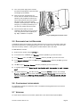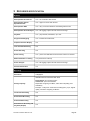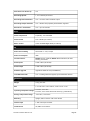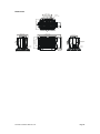
1
RECORDER Safety and Installation Manual © Copyright 20052006. All rights reserved. All other trademarks and copyrights referred to herein are the property of their respective holders. No part of this documentation may be reproduced in any form or by any means or used to make any derivative work, without written permission from the copyright holder, details of whom can be obtained from IVIEW Digital Video Solutions. This document is subject to change without written prior notice. Whilst IVIEW Digital Video Solutions makes every effort to ensure the accuracy and reliability of the information contained in this document, its employees and agents will not be responsible for any loss, however arising, from the use of, or reliance on, this information. Legal Notice: Parts of this product are protected by patents. Recorder Installation Manual v3.34 Page 2 Electromagnetic Compatibility (EMC) Warning This is a Class A product. In a domestic environment this product may cause radio interference, in which case the user may be required to take adequate measures. Manufacturer’s Declaration Of Conformance A Declaration of Conformity in accordance with the following EU standards has been made and is kept on file at the address shown on the last page. The manufacturer declares that the product supplied with this document is compliant with the provisions of the EMC Directive 89/336, the Low Voltage Directive LVD 73/23, the CE Marking Directive 93/68 EEC and all associated amendments. Specifications subject to change without notice. Recorder Installation Manual v3.34 Page 3 BEFORE YOU BEGIN Read these instructions carefully before installing or operating this product. Note: This equipment should be installed by a qualified service person and should conform to local and national regulations. This manual provides installation and operation information. To use this document you must have the following minimum qualifications: · a basic knowledge of CCTV systems and components · a basic knowledge of electrical wiring and lowvoltage electrical connections. INTENDED USE Use this product only for the purpose for which it was designed, as described in this manual and in the IVIEW360 user manual. ENVIRONMENTAL CONDITIONS Storage: –10° to +60°C, 14 to 140°F. The recorder should be allowed to acclimatize to its operational temperature range before power is supplied. Additionally, if the recorder is moved from a colder area to a warmer area, precautions should be taken to ensure that condensation is prevented. Operational: 5° to 35°C, 41 to 95°F. If a constant source of air flow is supplied to the product (e.g. fan blowing cool air over the unit) then the operational temperature range is increased to 5°C to 40°C, 41°F to 104°F. Recorder Installation Manual v3.34 Page 4 CONTENTS 1 PREFACE ............................................................................................................. 6 1.1 ABOUT THIS MANUAL ................................................................................. 6 1.2 CONVENTIONS USED IN THIS MANUAL ......................................................... 6 1.3 TRADEMARKS ........................................................................................... 6 2 INSTALLATION ...................................................................................................... 7 2.1 REQUIREMENTS ........................................................................................ 7 2.2 BEFORE INSTALLING THE RECORDER .......................................................... 7 2.3 RECORDER INSTALLATION CHECKLIST ........................................................ 8 2.4 INSTALLING THE RECORDER....................................................................... 9 2.4.1 Wiring and installing the recorder................................................... 9 2.5 DISCONNECTING THE RECORDER............................................................. 11 2.6 CONFIGURING THE RECORDER................................................................. 11 2.7 VERSIONS .............................................................................................. 11 3 RECORDER SPECIFICATION ................................................................................. 12 Recorder Installation Manual v3.34 Page 5 1 PREFACE 1.1 ABOUT THIS MANUAL This manual includes safety and installation instructions for installers, and should be used in conjunction with the separate user manual supplied with the camera. This document is intended to provide accurate information. However, the information it contains is subject to change without notice. IVIEW Digital Video Solutions, in keeping pace with technological advances, is a company of product innovation. This makes it difficult to ensure that all the information provided here is entirely accurate and uptodate. IVIEW Digital Video Solutions accepts no responsibility for any inaccuracies or omissions, and specifically disclaims any liabilities, loss, or risk, personal or otherwise, which is incurred as a consequence, directly or indirectly, of the use and/or application of any of the contents of this document. 1.2 CONVENTIONS USED IN THIS MANUAL WARNING statements identify potential hazards and problems that can occur if the equipment is handled improperly. WARNING: * Improper use of this equipment can cause severe bodily injury or equipment damage. *this symbol indicates electrical warnings and cautions CAUTION statements identify issues that can cause problems with the normal operation of the equipment. CAUTION: ** Ensure recorder has sufficient clearance when installed. **this symbol indicates nonelectrical warnings and cautions. TIP statements offer useful advice about operating the equipment. TIP: *** This setting can be individually controlled on each of your two video outputs. ***this symbol indicates important information. Notes: contain important information about a product or procedure. 1.3 TRADEMARKS All trademarks and registered trademarks that appear in this document, including (but not limited to) IMTERA™ are the property of their respective owners, details of which can be supplied by IVIEW Digital Video Solutions. Recorder Installation Manual v3.34 Page 6 2 INSTALLATION This chapter gives you a stepbystep guide to installing the recorder. 2.1 REQUIREMENTS Operation requirements The recorder is designed to work in tandem with a “recorderready” camera. Cable requirements The recorder requires a power cable and a dedicated interconnection cable (which is supplied with the unit). · The 24V AC/DC cable powers the recorder · The 3m/9ft 10” interconnection cable is for connecting the recorder to the camera Note: The recorder will also require an Ethernet cable if you intend to connect it to your local network to use such features as an NTP time server. WARNING Do not replace the interconnection cable, or use any other cable in its place: doing so could damage the recorder and/or the camera and will invalidate the warranty. Power requirements For optimal performance the recorder should be powered from an isolated 24V AC/DC source (using a cable less than 10m/33ft long), capable of providing 2 amps at 24V. WARNING Do not connect the recorder directly to the mains: this will damage the recorder and could result in severe injury. 2.2 BEFORE INSTALLING THE RECORDER · Check the components supplied with your recorder against the list below. Be sure nothing is missing. · Make sure you have all the tools needed for the installation (not supplied, but listed below). Recorder Installation Manual v3.34 Page 7 2.3 RECORDER INSTALLATION CHECKLIST Inside the box you will find: Quantity Item 1 Recorder 1 Plastic support bracket 3 M5 x 6mm/0.24” Pan Head Crosshead screws (for support bracket) 3 M5 shakeproof washers 1 Plastic connector cover 2 M3 x 6mm/0.24” Pan Head Crosshead screws (for the connector cover) 1 3m/9ft 10” interconnection cable 2 Ferrites 1 Installation manual You will also need: 1 Power supply unit 1 Crosshead screwdriver 1 Cable tie 1 Ground cable and set of fixings Recorder Installation Manual v3.34 Page 8 2.4 INSTALLING THE RECORDER CAUTION: Recorder Orientation The recorder must be installed vertically upright on a surface adequate to bear its full weight. Failure to comply with these instructions will invalidate the warranty. CAUTION: Ventilation Clearance 347mm / 13.70” 200mm / 7.90” Ensure recorder has sufficient clearance when installed. Refer to Fig. 2.1) Fig. 2.1) Ventilation clearances. Keep 200mm / 8” clear above the recorder for ventilation purposes. 2.4.1 WIRING AND INSTALLING THE RECORDER WARNING: You must complete steps 1) to 5) of this installation before supplying power to the unit. The recorder requires a 24V AC or DC power supply – this is not the same as the camera, which requires a 12V DC supply. Applying the wrong voltage to the recorder may damage it and will also invalidate the warranty. Refer to Fig. 2.2 for step 1) 1) Attach the plastic support bracket to the body of the recorder using the three screws supplied. Use only these screws and be sure to fit all three screws. CAUTION: Take care when handling the recorder: the device is heavy. Fig. 2.2) Connecting the plastic support bracket to the base of the recorder Recorder Installation Manual v3.34 Page 9 2) Use screws or other suitable fastenings to fix the recorder in its final position through the four holes in the plastic support bracket. To prevent ground loops and resulting picture interference, we recommend that you ground the recorder to a suitable building earth point. CAUTION: Ensure the recorder is stable in its final position, and that the unit itself stands vertically upright. Mounting the device in any other way will invalidate the warranty. 3) You must fit a safety wire or cable tie (not supplied) or fix the device physically in some way. You can do this by looping the wire through an attachment point in the ceiling and through the hole provided on the body of the recorder, to the right of the connector panel. CAUTION: The recorder must be securely fixed: failure to do so will invalidate the warranty. Fig. 2.3) Connection panel 4) Connect the recorder to the camera using the cable supplied. Be sure to connect the cable to the port marked Hires video (see Fig. 2.3)). Clip one of the ferrites around the cable as shown below, leaving enough room between the ferrite and the end of the cable to allow the end of the cable to fit inside the connector cover (fitted below). 3050cm (12”20”) from the end of the cable should be sufficient. The looped part should have a diameter of at least 4cm / 2”. CAUTION: Do not use any other cable than the one supplied; doing so will damage the recorder and will also invalidate the warranty. 5) If you wish, connect the recorder to your network using an Ethernet cable connected to the Ethernet port (Fig. 2.3)). Clip the remaining ferrite around the Ethernet cable as shown in the step above. 6) Connect the power cable to the recorder – remember that it requires 24V AC/DC, 2 Amps. Recorder Installation Manual v3.34 Page 10 7) Turn on the power supply to the recorder, and check the LED display. The Power LED should light up immediately. 8) After an interval of approximately one minute, when the recorder has successfully started up and completed its selftest, the second LED (marked with a heart symbol) will begin to flash. This shows that the recorder is working properly. If this LED does not light up, or remains permanently on or off, there is a problem with the recorder. 9) Once the Power LED is lit, and the ‘heartbeat’ LED is pulsing, fit the connector cover using the two screws supplied (see Fig. 2.4)). Installation is complete. Fig. 2.4) Fitting the connector cover 2.5 DISCONNECTING THE RECORDER You must shut down the recorder if you need to disconnect it or move it to a new location. Doing this will ensure that the drive is not damaged during the move, and no data is lost. Take care not to shut down the recorder by accident – nothing will be recorded while the disk is shut down. To shut down the recorder: 1) Enter the menu system using the MENU key. 2) In the main menu, use pq to go to Recorder and then press u to go to the next screen. 3) In the Recorder menu, use pq to go to Advanced and then press u to go to the next screen. 4) In the Recorder Advanced menu, use pq to go to Disk Operations and then press u to go to the next screen. 5) Use pq to go to Shut Down Recorder and then press u to go to the next screen. 6) A message appears saying Recording will be disabled until the recorder is reset. Are you sure? 7) The default response is No: use q to choose Yes, then press ENTER to confirm. The message Recorder disabled appears on screen, followed by Recorder Disconnected. At the top right you will then see the message Shutting off the recorder followed by You can now turn off your recorder. At this point you can now remove power from the recorder and disconnect it from the camera. 2.6 CONFIGURING THE RECORDER To configure the recorder for continuous, event, or scheduled recording please refer to the camera manual (section 6.4). 2.7 VERSIONS To check version numbers for the recorder, please refer to the camera manual (section 6.5.4). Recorder Installation Manual v3.34 Page 11 3 RECORDER SPECIFICATION Features Retrospective Pan and Tilt Yes – see a full 360° after the fact Retrospective Optical Equivalent Zoom Yes – approx. 4x zoom after the fact Retrospective VMD Yes – carry out motion detection and tracking after the fact Retrospective Scene Analysis Yes – left luggage, object removal and scene change Playback Yes – play forwards, backwards, up to 32x Single Frame Stepping Yes – forwards and backwards Graphical Timeline Display Yes Time and Date Searching Yes Event Searching Yes Event Locking Yes – protect user definable sections and/or events from erasure Motion Detection / Tracking Yes (accessed via camera) Scene Analysis Yes – left luggage, object removal and scene change Password Protection Yes Recording Resolution 3 Megapixel 400GB continuous rated Hard Disc Drive Eventbased: up to several months Continuous: up to several weeks Storage capacity Dependent on lighting conditions, frame rate and quality (user selectable) Example: ~5 days from continuous recording (24/7), 4 fps, highest quality, with 300 Lux lighting conditions Continuous Recording Yes Event Based Recording Yes Scheduled Recording Yes Simultaneous Recording and Playback (Duplex) Yes Recorder Installation Manual v3.34 Page 12 Auto Record on Power Up Yes Recording Speeds 1, 2 or 4 frames per second Recording Failure Detection Yes – on screen and/or via alarm output Recording Tamper Detection Yes – 384 bit hash proprietary authentication signature Record Pre / PostAlarm Yes – up to 30 seconds Video Video Compression Proprietary, user selectable Video Format PAL or NTSC (via camera) Mono / Colour Colour and B&W Night Mode (via camera) I/O Power Source Rating 24V AC/DC +/ 10%, 2 Amps Power Consumption 30W Control Protocol RS485: PelcoD, Vista PD; RS232: Bosch Autodome; all auto sensing; via camera Alarm Inputs 4 N/O or N/C (via camera) Alarm Output 1 N/O or N/C (via camera) Software Upgrade Upgrade enabled via LAN (10/100BaseT) Time/Date Generator Yes – including NTP time support; synchronised with camera Mechanical Weight 3.5 kg, 7lb 12oz Size L x H x W: 261 x 147 x 156mm; 10.28” x 5.79” x 6.14” Operating Temperature Range 5 to 35°C, 41 to 95°F 5 to 40°C, 41 to 122°F with forced air flow (e.g. external fan) Storage Temperature Range 10 to 60°C, 14 to 140°F Mounting Upright; within 3 metres / 10ft of the camera Camera Input 1 360° camera per recorder Certifications CE, EMC / FCC Class A Recorder Installation Manual v3.34 Page 13 Dimensions 105mm / 4.13” Diameter 5.8mm / 0.23” 118mm / 4.65” 40mm 40mm / 1.575” / 1.575” 3 x tapped M5 thread 120mm / 4.75” 261mm / 10.30” 192.1mm / 7.563” 4 x tapped M5 thread 156mm / 6.20” Recorder Installation Manual v3.34 40mm / 1.575” 78mm / 3.07” 147mm / 5.80” 80mm / 3.15” 40mm / 1.575” 132mm / 5.20” 78mm / 3.07” Safety lanyard locating hole 4 x tapped M5 thread 4 x tapped M5 thread each side Page 14 Distributed by IVIEW Digital Video Solutions Inc. For more information on the IVIEW Complete Video Surveillance System, visit: www.iviewsolutions.com Recorder Installation Manual v3.34 Page 15