1
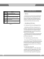
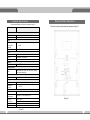
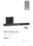
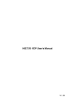
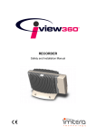
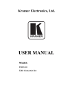
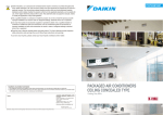
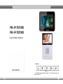
df OS Arm Call Monitor I nfo PM -IP-701TMD PM -IP-702TMD Unlock Pow er d 2-wire indoor monitors 1.2 Butto ns User manual SOS Arm Call Monitor Unlock Figure 1- 6 The buttons are illustrated in Figure 1- 6. Their descriptions are shown in Chart 1- 1 . 2 Basic Function Introduction No. Name Descript ion 1 SOS 2 Arm 3 Call 4 Monitor Monitor door station video. 5 Unlock Emergent calling management center Press the button during standby to enter arm/disarm interface Press the button when being called, you can answer call; press the button during a call, you can hang it up. Press this button during incoming call, calling, and monitoring, you can unlock corresponding door station. 2.1 Main Menu This product main menu consists of four menus, as video bidirectional talk, alarm, info search,system setup: in main menu, upper-left corner is network connection, main door station connection, DND setup and other status info, middle portion is current time(month, day,week and time), lower-right corner is arm/disarm button which allows selection between arm and disarm. 2.2 Video Bidirectional Talk Function Chart 1- 1 2. 2. 1 Bi di r e cti on a l Ta l k Fu n cti on w i th Ma n a g e men t C en ter Under all interfaces, press SOS button or “call management center” icon, VDP will switch to “calling management center” status, and a message will say “You are calling management center” with corresponding beep. When call is answered, bidirectional talk begins. You may end call by pressing SOS button again and VDP will return to standby interface. When management center calls VDP, VDP will ring. You may press call button or“answer” icon to answer call. You may end call by pressing call button again, and VDP will return to standby interface. 2. 2. 2 Vi de o B i di re cti ona l Ta l k wi t h D o or S ta ti on When door station calls VDP, VDP will ring and display video from door station. You may press call button or “answer” icon to answer call and achieve bidirectional talk with the door station. While VDP is displaying video from door station, you may end call and video by pressing call button or “end” icon and VDP will return to standby interface. 2.2.3 Bidirectional Talk with VDP Click to enter “video bidirectional talk” → “call resident”, input the resident's room number(i.e. Room 101, Unit 1, Building 1, and input 1-1-101. For VDP in current unit, only room NO. is required), click “call” icon (handset icon). The device will be in status of calling corresponding VDP, and the page displays “You are calling XX-X-XXXX” with beeps. When the residents answer, bidirectiona talk is enabled. You may end call and video by pressing call button or “end” icon. VDP will return to standby interface. 2.2.4 .4 Monitoring Function Under standby interface, press monitor button or under “video bidirectional talk” status press “monitor”, and VDP will displays video from door station. Under monitoring interface, you may switch to next video from door station since the device support 8- ch videos at the same time with 1 large window and 7 small windows. You may turn it off by pressing monitor button again and VDP will return to standby interface. 2.2.5 .5 Call Record Fu nctio n Under “video bidirectional talk” status click “call record”, you will see missed calls,received calls, and dialed calls, which include information of caller and time.You may go to different pages of records. You also may call, save, delete or delete all callers. 2.2.6 .6 Contacts Under “video bidirectional talk” status click “call resident”, you may enter contacts by clicking contacts icon (on the right of call box). The interface includes information of saved VDP info which allows direct operation to call, add, edit, delete and delete all.You may add by clicking blank or add button to add resident info. You may edit resident info by selecting saved info and click edit button. 2.3 Alarm Function and can set contents such as protection zone type, NO/NC, alarm type, enter delay, exit delay. For 1st to 3rd channels therein, users can only set NO/NC type; for the remaining 5 channels, users can set all, while protection zone types consist of IR, gas, smoke, SOS, door sensor, theft alarm, tripwire.Enter and exit time can be set to 0s, 10s, 30s, 60s, 90s and 120s. Delay is available only with delay alarm setup. Users can make bypass and delete each protection zone, or make the selected protection zone invalid once or for longer period. 2. 3.2 A la r m R e co rd ing Fu nc tio n Alarm recording mainly records information of the time alarm happens, protection zone NO., alarm processed or not. The alarm info will be updated to management platform synchronously. When alarm happens in any protection zone, there will be a 15s beep locally with alarm interface pops up. 2.3 .3 M od e Set up Alarm of this product consists of away mode, in mode, sleep mode, and user mode. You may set each mode to on/off separately for each protection zone. Default setup are as follows: Away mode: 1-8 channels all on; In mode: 1-3 channels on, others off; Sleep mode: 1-5 channels on, others off; User mode: all off. 2.4 Info Search Function This product can be connected to up to 8 channels alarm with 1st channel as SOS button, 2nd channel as gas alarm, 3rd channel as smoke alarm while the remaining5 channels can be exibly set. Under sub-menu there is information of protection zone status, alarm records and modesetup. After VDP receives messages (announcement) sent from platform, light turns on.Under “info search” click “announcement”, you may view announcements ranked by title and time. If you select one announcement and click search, you may view details of the selected announcement. 2 .3 .1 Pro te ctio n Zon e Sta tu s Functi on 2.5 System Setup Function This device mainly displays information of protection zone type, current status,and delay time for the 8 protection zones. Users may enter setup interface of protection zone by clicking setup button (password required), 6 System setup function includes user setup, project setup, and product introduction. 7 2.5.1 .1 U ser Setup User setup includes password setup, display setup, bidirectional talk setup, DND setup,restore default settings, a touch screen sound button plus touch screen clean button setup. 1. Password setup: includes passwords for user, arm, disarm with default 123456 and anti-attack password with default 654321. 2. Display setup: includes brightness (1-9), screensaver waiting time (from 30s to 1800s with every 30s as an interval). 3. Ring setup: ring selection for incoming call (.pcm format), alarm ring selection (.pcmformat), volume (0-10). 4. Bidirectional talk setup: Door station ring duration (15s, 30s, 45s,60s,90s,120s, adjustable); VDP ring duration (15s, 30s, 45s,60s,90s,120s, adjustable); Door station call duration (15s, 30s, 45s, 60s, 90s, 120s, adjustable); VDP call duration (5 min, 10 min, 15 min, 30 min, 45 min, 60 min, adjustable); Monitoring duration (15s, 30s, 60s, 90s, 120s, 180s, 300s, adjustable); 5. DND setup: select from 0 hour (0H), 1 hour (1H), 2 hours (2H), 4 hours (4H), 8 hours (8H) and 24 hours (24H) to block out local ring. 6. Restore default settings: restore all user settings to default. 7. Touch screen sound button: may select to have sound or not when you touch screen. 8. Touch screen clean button: after you turn on this option, the screen will be off in 45s which allow you to clean it up with a piece of dry cloth. 45s later, the screen will resume to normal status. You may exit anytime during the 45s by pressing unlock button. 2.5.2 2 .5 .3 Pro du ct In trod u ctio n This section mainly introduces product function and problems may encounter during usage. 2.6 Unlock Function Under incoming call from door station, call with door station and VDP monitoring door station, press unlock button to remotely unlock door. 2.7 Arm/Disarm Function Under arm/disarm status, click arm button at the lower right corner of main menu, and then select 1 from the 4 modes available (away, in, sleep and user mode). The password box pops up, and you need to input password for arming. System will enter arming status after delay ends. If you select instant arming, system will enter arming right after sound stops. Under arm status, click disarm button at the lower right corner of main menu and password box pops up. You need to input password for disarming. If you input correct password, the system will disarm; if you input incorrect password, you will see a message saying “incorrect password, please try again”. 2.8 Screen Cali bration Function This product screen was calibrated before shipped out. If you cannot activate icons on screen when you touch it, please press unlock+arm, and the product will enter screen calibration interface. Following the cursor, click on the 5 cursors in sequence to complete screen calibration. Once you have done, system will say screen calibration succeeds. .2 Project Setup This setup includes device info, network terminal, restore default settings. 1. Device info: includes room number, IP address, subnet mask, default gateway, MAC address,and version info. 2. Network terminal: includes door station name, device type, door station ID (manufacture use only), door station IP address, network port number, working status. You may edit each item by clicking it (a numeric keyboard pops up). After you complete setup, click the OK button on numeric keyboard. 3. Restore default settings: restore all project settings to default. 8 9 Technical Speci cati ons Device Interface Instruction Technical specications are as follows; please see Chart 3-1. The device interface is shown as follows, please see Figure 4-1. System Main Processor Built-in microcontroller Operating System Built-in LINUX system Video Video Compression Standard Video Resolution H.264 800x480 Audio Input All-direction microphone Output Embedded loudspeaker Bidirectional Talk Display Support bidirectional talk Screen Dimension 7 inch TFT full real color Operating Mode Input Mechanical button (SOS, arm, call, monitor, unlock), touch screen technology Alarm Alarm Input Network Support 8 channels alarm input Ethernet 10M/100Mbps self t Networking Protocol Specications TCP/IP Power DC 10~15V or AV direct feed Power Consumption Standby ≤ 1.5W ; Working ≤ 7W Working Environment Dimensions Weight -10℃~+60℃ 10~90%RH 261mm *92mm *25mm (L*W *H) 1.0 kg Chart 3- 1 Figure 4-1 No. Name Description 8-ch alarm, please see tag for details 1 Alarm Interface 2 Communication May directly connect to network cable or via corridor exchanger Port 3 Handset Interface Only models with earphone have this interface. 4 Power Interface Connect to 2-pin with 3.81 mm interface, 12V power Chart 4-1 Device Install ation Guide Figure 5-1 (1) Try to avoid exposing VDP to bad environment, such as condensation, high temperature, greasy dirt, dust, corrosion, direct sunlight and etc. (2) If there is abnormality after you plug in, you should unplug it immediately and unplug the device from power supply. You may plug in thedevice to power supply after troubleshoot. (3) Device installation and test must be done by professional staff. If there is any malfunction or failure, please do not try to dismount or x it by yourself, and please contact after-sales department for assistance. Please refer to Figure 5-1 as guide.