1
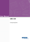
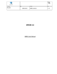
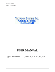
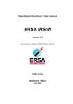
MN1010
GPS Receiver Module
1
Description
The Micro Modular Technologies MN1010 Global Positioning System (GPS) Receiver is a
complete, 12-channel receiver intended for OEM applications that measures only 10mm by 10mm by
2mm. It features fast-acquisition hardware, integrated RF filtering, flash memory and a TCXO. The
user needs only provide DC power and a GPS signal; the MN1010 will output the navigation solution
in the widely-used NMEA-0183 format.
The 12-channel receiver allows all satellites in view to be tracked, providing an over-determined
solution to minimize position jumps caused by individual satellite blockage. The fast-acquisition
hardware design greatly reduces the time for signal acquisition when the receiver is initially powered
up. The MN1010 requires a 1.8-volt supply and a separate 3-volt supply for the internal TCXO. For
even further power reductions, the OEM design may switch power or use a commanded powersaving mode.
The MN1010 is supported by an evaluation kit, including software, along with reference designs
to speed OEM development. The MN1010 is machine placeable by standard surface mount
equipment and is available in tape and reel. A metal shield is provided for RF protection and for
automated nozzle pickup.
1.1
1.2
Features
- Complete 12-channel GPS receiver including RF
filtering, flash memory and TCXO
- Less than 75 mW total power consumption for extended
battery life
- Ultra-small 10mm by 10mm by 2mm 36-pin LGA
package for automatic placement in a high volume
production environment
- Fast-acquisition design for rapid position determination
under all startup and operating conditions.
- Industrial temperature operation (-40°C to +85°C)
- Supports active antennas
- Standard NMEA-0183 serial messaging
- Pb free RoHS compliant
- Supported by hardware and software development kits
MN1010 (Lid Removed)
Block Diagram
Flash
Port 0
LNA
SAW
RF
Baseband
Port 1
RTC
(opt)
TCXO
GPIO
(opt)
Figure 1 - MN1010 Block Diagram
Micro Modular Technologies Pte. Ltd.
No. 3, Ubi Avenue 3, #05-01 Crocodile House 408857 Singapore
Tel: 65-6745-8832 Fax: 65-6293-0661 Email: [email protected]
www.micro-modular.com
MN1010
GPS Receiver Module
1.3
GPS Performance
Acquisition Time
Specification
Cold start TTFF (no time, no position, no ephemeris)
42 seconds (95% confidence)
Hot start TTFF (time, position and ephemeris, -130dBm
signal)
8 seconds (95% confidence)
Fast Start TTFF (time accurate to 10msec, position and
ephemeris, -130dBm signal)
<4 seconds (95% confidence)
Reacquisition
2 seconds (95% confidence)
Table 1 – Acquisition Performance
Positional Error
Accuracy
CEP (50%)
<3.0 meters
Table 2 – Positional Accuracy
Sensitivity
Typical
Tracking
-152 dBm
Acquisition (Cold Start, <5 minutes TTFF, 95% confidence)
-142 dBm
Table 3 – Sensitivity
Note: Above numbers are measured with an external 15 dB gain, 2 dB Noise Figure LNA.
2
Environmental
2.1
Operating
Temperature
-40°C to +85°C
Humidity
Up to 95% non-condensing or a wet bulb
temperature of +35°C, whichever is less
Altitude
-1000 feet to 60,000 feet
Table 4 – Operating Requirements
2.2
Storage
Temperature
-40°C to +85°C
Humidity
Up to 95% non-condensing or a wet bulb
temperature of +35°C, whichever is less
Altitude
-1000 feet to 60,000 feet
Shock
18G peak, 5 millisecond duration
Shock (in shipping container)
10 drops from 75 cm onto concrete floor
Table 5 – Storage Requirements
Micro Modular Technologies Pte. Ltd.
No. 3, Ubi Avenue 3, #05-01 Crocodile House 408857 Singapore
Tel: 65-6745-8832 Fax: 65-6293-0661 Email: [email protected]
Page 2 of 15
www.micro-modular.com
MN1010
GPS Receiver Module
3
Electrical
3.1
Module Pin Descriptions
Pin
Name
Pin Definition
1
FREF
This pin should be left unconnected.
2
GND
GND
3
+1.8V
Power
4
¯SERBOOT
¯¯¯¯¯¯¯¯
This pin is a digital input. For normal operation, it is pulled high and the
MN1010 will start executing code from on-board flash upon system reset or
¯ ¯ ¯ ¯ ¯ ¯ ¯ ¯ is pulled active (low), then the MN1010 will enter
power-up. If ¯SERBOOT
boot mode upon reset or power-up to receive programming information in
LOD format. This feature can be used to download a flash re-programmer
into on-board RAM to update or change flash code. The state of the
¯SERBOOT
¯ ¯ ¯ ¯ ¯ ¯ ¯ ¯ line is only read upon power-up or system reset. Refer to
Section 4.1 for further information.
5
RX1
The MN1010 GPS Receiver Module implements two, full-duplex
asynchronous serial UART ports. This signal is the input for the second
UART and may be used to input commands or additional information to the
receiver. In the idle condition, this pin is driven at logic 1. If the driving
circuitry is powered independently of the MN1010, ensure this pin is not
driven to logic 1 when the supply to the MN1010 is removed.
6
TX1
The MN1010 GPS Receiver Module implements two, full-duplex
asynchronous serial UART ports. This signal is the output for the second
UART. In the idle condition, this pin is at logic 1.
7
RX0
The MN1010 GPS Receiver Module implements two, full-duplex
asynchronous serial UART ports. This signal is the input for the first UART
and is normally used to input commands to the receiver in either binary or
NMEA format depending upon the configuration of the receiver. In the idle
condition, this pin is driven at logic 1. If the driving circuitry is powered
independently of the MN1010, ensure this pin is not driven to logic 1 when
the supply to the MN1010 is removed. As a second function, if this pin is
pulled active (low), then RX0 receives LOD formatted programming
information after power up or reset.
8
TX0
The MN1010 GPS Receiver Module implements two, full-duplex
asynchronous serial UART ports. This signal is the output for the first UART
and is normally used to output position, time and velocity information from
the receiver in either binary or NMEA format depending upon the
configuration of the receiver. In the idle condition, this pin is at logic 1.
9
1PPS
This pin outputs a one-pulse-per-second (1PPS) signal, and is active when
the fix is valid.
10
+1.8V
Power
11
GND
GND
12
EXTRTC_INT2 If an external RTC IC (Seiko S-35390A) is used, connect this pin to the INT2
line of the RTC IC with a 10K pullup to +1.8V. If not used, leave open.
13
EXTRTC_SCL
If an external RTC IC (Seiko S-35390A) is used, connect this pin to the SCL
line of the RTC IC with a 10K pullup to +1.8V. If not used, leave open.
14
N/C
No-connect
Micro Modular Technologies Pte. Ltd.
No. 3, Ubi Avenue 3, #05-01 Crocodile House 408857 Singapore
Tel: 65-6745-8832 Fax: 65-6293-0661 Email: [email protected]
Page 3 of 15
www.micro-modular.com
MN1010
GPS Receiver Module
Pin
Name
Pin Definition
15
N/C
No-connect
16
EXTRTC_SDA If an external RTC IC (Seiko S-35390A) is used, connect this pin to the SDA
line of the RTC IC with a 10K pullup to +1.8V. If not used, leave open.
17
RTC_IN
The MN1010 provides for an optional RTC clock crystal to maintain time of
day when the MN1010 is in a power sleep condition. If the hot start mode of
operation is not required, then the real time clock is not needed and the
crystal can be eliminated. If use of an internal RTC is desired, connect this
pin to one side of a 32.768 KHz clock crystal and a shunt capacitor returned
to the 1.8-volt DC supply. See Section 7 for additional information on the
RTC crystal and recommended capacitors. If an external 32.768 KHz clock
signal is available, it may be presented at this pin. The logic levels must
match the logic levels of the MN1010. If an external RTC IC (Seiko S35390A) is used this pin is connected to the INT1 line of the RTC IC.
18
RTC_OUT
The MN1010 provides for an optional RTC clock crystal to maintain time of
day when the MN1010 is in a power sleep condition. If the hot start mode of
operation is not required, then the real time clock is not needed and the
crystal can be eliminated. If use of an internal RTC is desired, connect this
pin to one side of a 32.768 KHz clock crystal and a shunt capacitor returned
to the 1.8-volt DC supply, otherwise, leave this pin open. See Section 7 for
additional information on the RTC crystal and recommended capacitors.
19
N/C
No-connect
20
VALID_FIX
This pin is used to indicate that the receiver has acquired a valid fix.
21
+1.8V
Power
22
N/C
No-connect
23
¯¯¯¯¯¯
RESET
To properly initialize the MN1010, a reset pulse must be supplied whenever
the power supply is cycled. In addition, to prevent corruption of the on-board
flash, the reset line should be pulled low whenever the 1.8-volt power supply
falls out of tolerance, such as during a powering up or powering down of the
host platform. The reset line should be held in the reset (logic low) state until
15 msec after the 1.8-volt and 3.0-volt power supplies have stabilized within
proper tolerance.
24
GND
GND
25
+1.8VVCO
Power
26
+1.8VIF
Power
27
GND
GND
28
+1.8V for LNA
Power
29
GND
GND
30
ANT
RF Input: Connect to external antenna. See Section 3.3, RF Interface
31
GND
GND
Micro Modular Technologies Pte. Ltd.
No. 3, Ubi Avenue 3, #05-01 Crocodile House 408857 Singapore
Tel: 65-6745-8832 Fax: 65-6293-0661 Email: [email protected]
Page 4 of 15
www.micro-modular.com
MN1010
GPS Receiver Module
Pin
Name
Pin Definition
32
¯RFEN
¯¯¯¯
This pin is a digital output enabling optional power control to the internal
LNA and TCXO to reduce power consumption during SLEEP mode. This
signal can be used to drive a FET or other suitable device to control power
to the +1.8V LNA and +3V TCXO power pins. Orion software will drive this
pin high when it receives a SLEEP command. This signal may then be used
to disable the +1.8V LNA and/or +3V TCXO supplies. If control of these
power supplies is not required, this pin should be left unconnected. During
power up or processor reset, this pin is driven low.
33
+3V for TCXO
Power
34
+1.8VRF
Power
35
TPI
This pin is used for factory test and must be tied to ground through a
10Kohm resistor.
36
TPQ
This pin is used for factory test and must be tied to ground through a
10Kohm resistor.
Table 6 – MN1010 Pin Description
3.2
Power Supply
The MN1010 GPS Receiver Module is designed to operate from two supply voltages, the main
voltage of 1.8 volts, and a secondary low current supply voltage of 3.0 volts for the internal TCXO.
The main 1.8 volts supply is fed into several voltage pins of the MN1010 GPS Receiver Module.
Suitable decoupling and isolating of the individual power supply pins must be provided by external
decoupling circuitry. In addition, optional power control may be added to select power supply pins to
further reduce power consumption in standby and/or sleep modes. See the Reference Design Notes
(Table 16 – Referenced Documents for MN1010 Data Sheet) for suggested decoupling values.
Voltage
1.8 VDC ± 5%
Current (typical)
35 mA
Current (maximum)
40 mA
Table 7 – Main Power Supply
Voltage
3.3 VDC ± 0.3 VDC
Current (typical)
2 mA
Current (maximum)
3 mA
Table 8 – TCXO Power Supply
Micro Modular Technologies Pte. Ltd.
No. 3, Ubi Avenue 3, #05-01 Crocodile House 408857 Singapore
Tel: 65-6745-8832 Fax: 65-6293-0661 Email: [email protected]
Page 5 of 15
www.micro-modular.com
MN1010
GPS Receiver Module
3.3
RF Interface
3.3.1
RF Input
The MN1010 GPS Receiver Module accepts a standard GPS L1 signal from a passive or active
antenna on the RF input pad of the module, which is pin 30, the ANT pin. If a passive antenna is
used, no other circuitry is required. However, if an active antenna is required, then suitable means
for powering the active antenna must be provided external to the MN1010 GPS Receiver Module.
The RF input is isolated from DC levels to a maximum of ±15 VDC
If power is required for an active antenna, MMT recommends that a quarter wave stub be used to
prevent disturbing the matching of the antenna and MN1010 module. The other end of the quarter
wave stub should be AC grounded with a suitable microwave quality capacitor. See the Reference
Design Notes (Table 16 – Referenced Documents for MN1010 Data Sheet) for more detail.
Signal Level
-151 dBm to -125 dBm typical
Frequency
L1 (1575.42 MHz)
Return Loss
Better than -5.5 dB
Noise Figure
7 dB typical
Impedance
50 ohms nominal
Table 9 – RF Signal Characteristics
The MN1010 GPS Receiver Module has a noise figure of 7 dB typically. With high quality high gain
passive antennas this will provide adequate performance in low-cost environments. Using an
external LNA of 2 dB NF and approximately 15 dB of gain will improve the performance of the
receiver to work with a wider range of passive antennas.
3.3.2
Burnout Protection
The MN1010 GPS Receiver Module can accept signal levels up to -20dBm with a DC voltage of
+6VDC on the RF input pin without permanent damage to the module.
Micro Modular Technologies Pte. Ltd.
No. 3, Ubi Avenue 3, #05-01 Crocodile House 408857 Singapore
Tel: 65-6745-8832 Fax: 65-6293-0661 Email: [email protected]
Page 6 of 15
www.micro-modular.com
MN1010
GPS Receiver Module
3.3.3
Jamming Performance
J/S versus Frequency for Loss of Sensitivity
nominal GPS level of -135 dBm
120
110
100
J/S Ratio
90
1 dB Loss
80
2 dB Loss
70
5 dB Loss
60
50
40
30
1550
1560
1570
1580
1590
1600
Frequency (MHz)
Figure 2 – Jamming Performance
3.4
Signal Interface
3.4.1
Digital Interface Levels
VCC is nominally 1.8 VDC.
VIH(min)
0.7 x Vdd
VIH(max)
Vdd + 0.3 Vdc
VIL(min)
-0.3 Vdc
VIL(max)
0.3 x Vdd
VOH(min)
0.8 * Vdd
VOH(max)
Vdd
VOL(min)
0 Vdc
VOL(max)
0.22 * Vdd
Table 10– Digital I/O Interface Levels
3.4.2
Serial Interface
Two serial data ports provide data communications to and from the MN1010 GPS Receiver Module.
Micro Modular Technologies Pte. Ltd.
No. 3, Ubi Avenue 3, #05-01 Crocodile House 408857 Singapore
Tel: 65-6745-8832 Fax: 65-6293-0661 Email: [email protected]
Page 7 of 15
www.micro-modular.com
MN1010
GPS Receiver Module
3.4.2.1 Supported data formats and bit rates
The MN1010 data format is 8 bits, no parity, and 1 stop bit. The default bit rate is specified by the
software loaded into flash. However, the user can change it from 4800 bps to 115kbps. During
¯ ¯ ¯ ¯ ¯ ¯ ¯ ¯ is pulled
firmware reprogramming, the serial port defaults to 9600 bps upon reset if ¯SERBOOT
active (low).
4
Software Interface
4.1
Programming the on-board flash
The on-board flash device can be reprogrammed to update the firmware on the MN1010, or to
¯ ¯ ¯ ¯ ¯ ¯ ¯ ¯ line, which is normally held in logic
replace the firmware with a customized version. The ¯SERBOOT
1 (high) state, is pulled to logic 0 (low) and the power cycled or a reset issued.
The typical procedure for re-flashing the MN1010 is to use the MMT-supplied utility to verify proper
connection to the device, then download a RAM based flash utility, which upon startup will change
the bit rate to 115K bps, download the flash and then verify the flash contents.
Serial port 0 will issue a hexadecimal $55 (ASCII upper case U) at 9600 bps. MMT will supply a flash
programming utility that runs on a standard PC-compatible machine running the Windows operating
system. The procedure for reprogramming the flash consists of the following steps:
¯ ¯ ¯ ¯ ¯ ¯ ¯ ¯ line low.
1. Pull ¯SERBOOT
2. Reset the MN1010 by power cycling or sending a reset signal.
3. Detect the hexadecimal $55.
4. Using the MMT flash utility, download the flash loader program into on-board RAM.
5. Using the MMT flash utility, erase the on-board flash.
6. Using the MMT flash utility, download the new firmware image and program into the onboard flash.
¯ ¯ ¯ ¯ ¯ ¯ ¯ ¯ line high.
7. Pull ¯SERBOOT
8. Reset the MN1010 by power cycling or sending a reset signal.
9. If flash is programmed correctly, the MN1010 will execute the new software code.
4.2
NMEA Standard Output Messages
The MN1010 sends the following NMEA-018 v3.0 standard sentences:
ID
Description
DTM
Datum Reference
Orion
GGA
GPS fix data
GLL
GPS Position – Latitude & Longitude
GSA
DOP and active satellites
Y (D)
GSV
Satellites in view
Y (D)
RMC
Recommended Minimum GNSS Data
Y (D)
VTG
Course over ground and ground speed
Y
ZDA
Time and date
Y
Y
Y (D)
Y
D = Enabled by default
Table 11 – Standard NMEA Output Sentences
Micro Modular Technologies Pte. Ltd.
No. 3, Ubi Avenue 3, #05-01 Crocodile House 408857 Singapore
Tel: 65-6745-8832 Fax: 65-6293-0661 Email: [email protected]
Page 8 of 15
www.micro-modular.com
MN1010
GPS Receiver Module
4.3
NMEA Proprietary Output Message
The MN1010 sends the following NMEA-0183 proprietary sentences:
Orion
ID
Description
echo
Echo of input command
$PUNV,CFG_R
Response to CONFIG command
$PUNV,ERR
Error response
Table 12 – Proprietary NMEA Output Sentences
4.4
NMEA Proprietary Commands
The MN1010 recognizes the following NMEA-0183 proprietary commands:
Orion
ID
Description
$PUNV,GETCONFIG
Read configuration parameters
$PUNV,CONFIG
Set configuration parameters
$PUNV,SLEEP
Enter sleep mode
$PUNV,START
Start Navigation
$PUNV,STOP
Stop Navigation
Table 13 – Proprietary NMEA Commands
For detailed information regarding these messages, please refer to the NMEA User Manual.
5
EMI/EMC
5.1
EMI Requirements
As the MN1010 is a component used on a circuit board assembly, it is not required nor is it specified
to comply with EMI or EMC regulations.
5.2
Receiver Frequency Plan
The MN1010 implements a single down-conversion quadrature IF receiver which then is fed into the
digital baseband processor.
Receiver Parameter
Specification
TCXO Frequency
16.3676 MHz
Local Oscillator Frequency
1573.874 MHz
IF Frequency
1. 54604 MHz
Baseband processor Clock Frequeny
16.3676 MHz
Table 14 – Receiver Frequency Plan
6
Power Supply Decoupling and Switching
Each power supply pin should by bypassed with a good quality RF ceramic capacitor resonant
around 1.5 GHz. The 1.8-volt RF pin should be bypassed with a 27pF, 1000pf and 4.7uF capacitor to
ground. This pin should be fed with an 18 ohm resistor to +1.8 volts.
Micro Modular Technologies Pte. Ltd.
No. 3, Ubi Avenue 3, #05-01 Crocodile House 408857 Singapore
Tel: 65-6745-8832 Fax: 65-6293-0661 Email: [email protected]
Page 9 of 15
www.micro-modular.com
MN1010
GPS Receiver Module
If a switching power supply is used, it is important that the switching noise be kept below 50 mV
peak-to-peak. As the switching frequency gets closer to the IF frequency, the switching noise will
have to be further reduced to eliminate interference.
7
RTC Crystal Specification
Frequency
32.768 KHz
Type
Tuning fork crystal
Load capacitance
12 pf (see below)
Shunt capacitors
The series combination of the input and output shunt capacitor must equal
the load capacitance for the selected RTC crystal. When calculating the
capacitor values, it is important to consider the 3 pf per pin capacitance of
the MN1010 device. The other end of the shunt capacitors must be tied for
the +1.8-volt power supply to ensure proper RTC startup.
Table 15 – RTC Crystal Specs
8
Referenced Documents
MMT NMEA User Manual for Orion
MN1010 Design Guidelines
MN1010 Evaluation Kit User Guideline
Table 16 – Referenced Documents for MN1010 Data Sheet
9
Packaging and Marking Information
9.1
Component Marking
Figure 3 – Marking
Note the JEDEC Pb-free symbol is also used as the pin 1 identifier for the MN1010.
Micro Modular Technologies Pte. Ltd.
No. 3, Ubi Avenue 3, #05-01 Crocodile House 408857 Singapore
Tel: 65-6745-8832 Fax: 65-6293-0661 Email: [email protected]
Page 10 of 15
www.micro-modular.com
MN1010
GPS Receiver Module
9.2
Packaging Drawing
Figure 4 – Package Outline
Note the JEDEC Pb-free symbol is also used as the pin 1 identifier for the MN1010.
9.3
Recommended PCB Footprint
Figure 5 – Recommended PCB Footprint
Figure 5 is a suggested PCB footprint for the MN1010. The user may need to adjust the pad dimensions
based upon their manufacturing process. While solder mask covered traces are permissible underneath the
MN1010, exposed vias or pads should be avoided.
Micro Modular Technologies Pte. Ltd.
No. 3, Ubi Avenue 3, #05-01 Crocodile House 408857 Singapore
Tel: 65-6745-8832 Fax: 65-6293-0661 Email: [email protected]
Page 11 of 15
www.micro-modular.com
MN1010
GPS Receiver Module
9.4
Tape and Reel Information
The MN1010HS is provided in standard tape and reel, with 2K devices per reel.
Dimensions
Nominal
Tolerance
W
24.00
0.3
P
16.00
0.1
Ao
10.40
0.1
Bo
10.40
0.1
Ko
1.50
0.1
K1
0.40
0.1
Ps
4.00
0.1
F
11.50
0.1
Figure 6 – Carrier tape dimensions (in mm)
Reel Part No.
SMD/H4/W24
A
330
W
24.4
B
100
F
2.2
G
90°
Figure 7 – Reel Dimensions (in mm)
Micro Modular Technologies Pte. Ltd.
No. 3, Ubi Avenue 3, #05-01 Crocodile House 408857 Singapore
Tel: 65-6745-8832 Fax: 65-6293-0661 Email: [email protected]
Page 12 of 15
www.micro-modular.com
MN1010
GPS Receiver Module
Figure 8 – Orientation in tape
9.5
Tube packaging
The MN1010 is also available in tube form, with 48 devices per tube. The length of the tube is
501mm ± 0.1mm.
Figure 9 – Tube dimensions (in mm)
Micro Modular Technologies Pte. Ltd.
No. 3, Ubi Avenue 3, #05-01 Crocodile House 408857 Singapore
Tel: 65-6745-8832 Fax: 65-6293-0661 Email: [email protected]
Page 13 of 15
www.micro-modular.com
MN1010
GPS Receiver Module
9.6
Recommended Reflow Profile
Figure 10 – Reflow Profile
Reflow Parameter
Specification
Preheating Rate
2.5°C/seconds
Soaking Temperature
140°C to 170°C
Soaking Time
80 seconds
Peak Temperature
260°C
Reflow Time over Liquidus
60 seconds
Cool down Rate
2.5°C/seconds
Table 17 – Reflow Parameters
10
Ordering Information
The ordering part numbers are contained in the table below:
Ordering Part Number
Description
MN1010-RO
MN1010 in tape & reel with Orion Software
MN1010-TO
MN1010 in tube with Orion Software
Table 18 – Ordering Information
Micro Modular Technologies Pte. Ltd.
No. 3, Ubi Avenue 3, #05-01 Crocodile House 408857 Singapore
Tel: 65-6745-8832 Fax: 65-6293-0661 Email: [email protected]
Page 14 of 15
www.micro-modular.com
MN1010
GPS Receiver Module
11
Notices
All reference and informational documents (including marketing information, specifications, reference
designs, etc.) are provided for information only and are subject to change without notice. Reasonable
efforts have been made in the preparation of these documents to assure their accuracy, however
Micro Modular Technologies Pte. Ltd. assumes no liability resulting from errors or omissions in this,
or any document, or from the use of the information contained herein. Micro Modular Technologies
Pte. Ltd. reserves the right to make changes in the product design and specifications as needed and
without notification to its users. Please check our website for the most current documentation. All
information contained herein is the property of Micro Modular Technologies Pte. Ltd. and may not be
copied or reproduced, other than for your information, without prior written consent.
12
Contact Information
Corporate Headquarters
Micro Modular Technologies Pte. Ltd.
No. 3, Ubi Avenue 3, #05-01
Crocodile House, Singapore 408857
Americas and Europe
Micro Modular Technologies Americas
14720 Creekside Lane
Longmont, CO 80503, U.S.A.
Tel: (65) 6745 8832
Fax: (65) 6293 0661
Email: [email protected]
Tel: (1) 303-482-2842
Fax: (1) 303-339-0398
Email: [email protected]
For a list of Regional Sales Representatives,
please see our web page:
www.micro-modular.com
Document no: MN1010_DS_080614
Micro Modular Technologies Pte. Ltd.
No. 3, Ubi Avenue 3, #05-01 Crocodile House 408857 Singapore
Tel: 65-6745-8832 Fax: 65-6293-0661 Email: [email protected]
Page 15 of 15
www.micro-modular.com