1
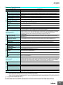
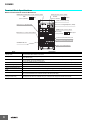
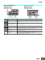
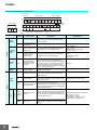
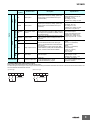
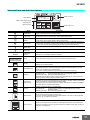
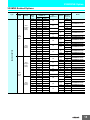
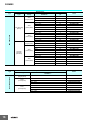
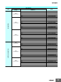
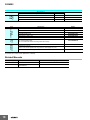
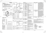
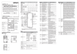
3G3MX2 Control Circuit Terminals Specifications Communication RS-485 Logic common and power supply Logic input Shorting bar Relay output Communication Pulse Pulse Analog input and output input power supply RS-485 Terminal symbol Analog Power supply Logic output Description Specifications SC Input signal common This is a common terminal used by the internal power supply, digital input and analog input/ output terminals. FS Frequency reference power supply 10 VDC power supply for the FV terminal. Allowable max. current: 7 mA FV Frequency reference input terminal (analog voltage input) Use this terminal if the frequency reference is provided by 0 to 10 VDC voltage input. Input impedance Approx. 10 k Allowable input voltage range 0.3 to +12 VDC FI Frequency reference terminal (analog current input) Use this terminal if the frequency reference is provided by 4 to 20 mA current input. Input impedance 100 Allowable input range 0 to 24 mA Frequency setting input Sensor input S5/TH External thermistor input (also used as multi-function input terminal) Connect an external thermistor between the SCs, to trip the Inverter when a temperature error occurs. (The inverter will trip when the input from thermistor is approx. 3 k or higher.) Since this PTC type input is also used as the multi-function input terminal, setting of C005 is required. For details, refer to User’s Manual (I570). Output AM Multi-function analog output (voltage) Specified signals can be output using voltage signals of 0 to 10 VDC. SC Input signal common This is a common terminal used by the internal power supply, digital input and analog input/ output terminals. P24 24 VDC power supply for contact input Power supply terminal signal.This is used as a common terminal if the for input signal source logic is input. PSC Sink logic input: Shorted with P24 Source logic input: Shorted with SC Power supply terminal To drive the contact input using an external power for input terminal supply, remove the shorting bar. For details, refer to User’s Manual (I570). S7/EB S6 S5/TH S4/GS2 S3/GS1 S2 S1 Multi-function input terminal S4/GS2 S3/GS1 Safety input Contact Input Digital Power supply 8 Terminal name Analog output AM Allowable max. current: 100 mA Select 7 functions from among 59, and allocate them to terminals S1 through S7/EB. Both sink Voltage between each input and PSC and source logics are supported. For details, refer ON voltage: 18 V min. to User’s Manual (I570). OFF voltage: 3 V max. Allowable max. voltage: 27 VDC Load current: 5 mA (at 24 V) Enabled when the safety function selector switch is turned ON. For details, refer to User’s Manual (I570).