1
62
Spyder3 SG-34 GigE Vision Color Manual
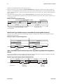
Internal Line Trigger, External Direction Control, Internal frame
trigger
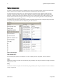
Set the Fram e Start Trigger and Fram e Active Trigger valu es to off, as d escribed above. Set the Line Trigger
Mod e valu e to Off and the Exposu re Mod e, Exposu re Tim e and Line Rate as above.
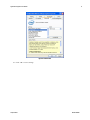
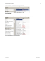
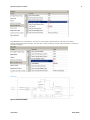
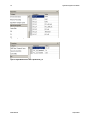
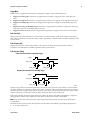
In the Direction Control Grou p > set the Sensor Scan Direction to External.
Set the Inpu t Direction Signal to Line 2 (as d escribed at the start to this section).
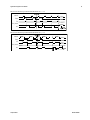
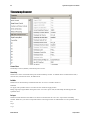
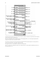
Figure 35: Scan Direction
External Line Trigger, Internal Direction Control, Internal frame
trigger
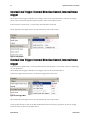
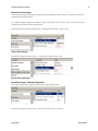
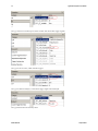
In the Direction Control Grou p > set the param eter Sensor Scan Direction > to Forw ard or Reverse, d epend ing
on you r ap plication.
Set the Fram e Start Trigger and Fram e Active Trigger valu es to off, as d escribed above.
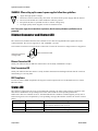
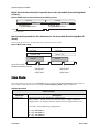
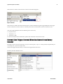
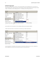
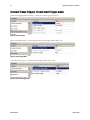
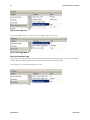
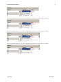
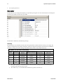
In the Line Trigger Fu nction Grou p > Set the Line Trigger Mod e valu e to On.
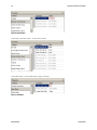
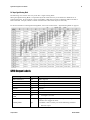
Figure 36: Line Trigger Mode
Set the Inpu t Direction Signal to Line 0 (as d escribed at the start to this section).
Verify the line frequ ency valu e by clicking the Read External Line Frequ ency param eter in the Line Trigger
Fu nction Grou p, as show n in the figu re above.
03-032-20124-00
Teledyne DALSA