1
Spyder3 SG-34 GigE Vision Color Manual
69
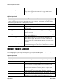
Outputs
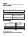
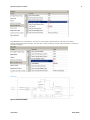
Ou tpu ts are u sed to control external d evices and m onitor internal signals.
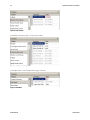
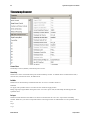
Step 1
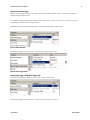
Select the ou tpu t line.
Step 2
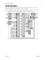
Set the Signal Rou ting Block param eter. Refer to section ―PLC Inpu t Signal Rou ting Block‖ for m ore d etail
abou t PLC settings.
Important N ote: Signals PLC_10 to PLC_15 shou ld not be changed u nless you are very experienced w ith
triggers and PLC settings.
Step 3
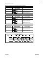
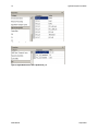
Set the signal ou tpu t: Q0 to Q3.
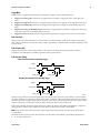
Use the looku p table to ou tpu t signals to one of 4 GPIO ou tpu ts.
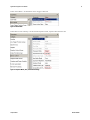
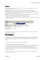
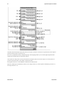
Figure 53: Output Selector
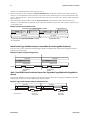
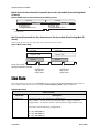
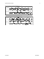
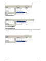
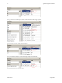
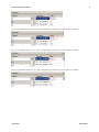
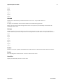
The signal to ou tpu t can be selected from the Signal Rou ting Block p aram eters. For exam ple, the follow ing
figu res w ill ou tpu t line 0. Please note that the fram e valid (PLC_A4) is alw ays high since Spyd er3 is a line scan
cam era.
Teledyne DALSA
03-032-20124-00