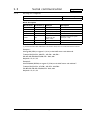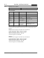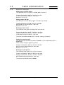
1
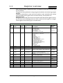
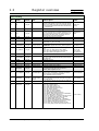
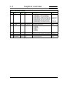
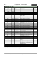
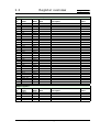
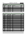
MAC800
Integrated Servo Motors
Preliminary
Technical user manual
JVL Industri Elektronik A/S
LB0052-11GB
Revised 1.3.2006
1
Register definitions
JVL A/S - Technical user Manual - Integrated Servo Motors MAC800
6
1.1
Description of Data Formats
The MAC motor uses 3 different data formats:
•
•
•
Long Int
Fixed16
Fixed24
Long Int:32 bit signed.
Range: -2.147E9 ... +2.147E9
Fixed16:16 bit signed fixed point.
Range: -32768.0 ... +32767.9999847
Unit: 1 / 65536.
Fixed24:24 bit signed fixed point.
Range: -128.0 ... +127.99999994
Unit: 1 / 16777216.
7
JVL A/S - Technical user Manual - Integrated Servo Motors MAC800
Only MAC800
1.2
Register overview
Only MAC800
When using the RS232 or RS422 serial links, it is possible to access all the internal registers in the motor.
This gives the same possibilities as using the general installation and monitoring program
MacTalk.
In addition to these features, many more are accessible. In total, the MAC motor contains
more than 200 internal registers such as nominal velocity, actual position, etc.
Important note:
All registers can be read without any risk but please note that several registers are not
for the normal user and damage may occur if the contents of these registers is changed.
These registers are marked in grey in the table below.
Main Control
Reg.
no.
Name
Width
Unit
Description
1
PROG_VER.
Long int
-
Shows the actual version of the firmware.
Bit0-5: Minor version
Bit6-12: Major version
Bit13: (if set) Beta version
Bit14: Reserved
Bit15: (if set) MAC400 or MAC800
MacTalk
name
(status bar)
The current MAC motor mode:
(see also register 37 - “Start mode”)
0: Passive
1: Velocity
2: Position
3: Gear Mode
4: Analog Torque (direct)
5: Analog Velocity
6: Analog Velocity/Gear.
7-11: Reserved for special purposes
12: Torque zero search
13: Sensor type 1 zero search
14: Sensor type 2 zero search
16: Analogue velocity (with deadband)
17: Velocity/analogue torque
18: Analogue gear
19: Coil
20: Air cylinder
21: Analogue to position
Mode
Encoder counts
The commanded position
Position
Encoder counts
Offset position for position change
Max velocity
2
MODE_REG
Long int
-
3
P_SOLL
Long Int
4
P_NEW
Long Int
5
V_SOLL
Long Int
Counts/sample/16
Desired velocity 1 RPM=2.77056 counts/sample.
Example: To obtain 100 RPM, V_SOLL must be set to
277.
6
A_SOLL
Long Int
Counts/sample²/16
The desired nominal acceleration.
1000 RPM/s = 3.598133 counts/Sample²
Example: To obtain 100000 RPM/s, A_SOLL must be
set to 360.
Acceleration
7
T_SOLL
Long Int
-
The maximum allowed torque. 0-1023.
1023 = 300% (full peak torque).
Torque
8
P_FUNC
Long Int
Encoder counts
-
-
9
INDEX_OFFSET
Long Int
Encoder counts
Distance from encoder index to ext. sensor
-
10
P_IST
Long Int
Encoder counts
The actual motor position
Actual
position
11
V_IST_16
Long Int
Counts/sample/16
V_IST (actual speed) measured over 16 samples
Same unit as V_SOLL (register 5).
Actual velocity
-
12
V_IST
Long Int
Counts/sample
Actual velocity. 1RPM=0.17316 counts/sample.
13
KVOUT
Fixed 16
-
Overall servo filter inertia factor.
Load
14
GEARF_1
Long Int
-
Gear output factor. Used in gear mode
Input
15
GEARF_2
Long Int
-
Gear input factor. Used in gear mode
Output
JVL A/S - Technical user Manual - Integrated Servo Motors MAC800
8
1.2
Register overview
Only MAC800
Error Handling
Reg.
no.
Name
Width
Unit
Description
16
I2T
Long Int
-
Motor temperature calculated. The value is integrated
during motor operation. If it reaches 100% the overload
bit in reg 35 (ERR_STAT bit 0) is set indicating that the
motor torque has passed the allowable continues rating
= nominal torque.
Motor load
(mean)
17
I2TLIM
Long Int
-
Error trip level used for I2T register.
Regenerative
load
18
UIT
Long Int
-
Returned energy from the motor (load). If the value
passes 100% the UIT bit in register 35 (ERR_STAT bit
3) is set indicating that too much energy has been returned from the motor (load). Connect an external
dump resistor or decrease deceleration.
19
UITLIM
Long Int
-
Error trip level used for UIT register
-
20
FLWERR
Long Int
Encoder counts
Actual follow error
Follow error
VDC/74.4713
Logic supply voltage measurement. Logic supply voltage [VDC] = U_24V x 0.013428
Logic supply
EH:Follow error
21
U_24V
Long Int
22
FLWERRMAX
Long Int
Encoder counts
Follow error limit. If the follow error passes this limit the
motor will be stopped and the FLW_ERR in register 35
will be set.
23
UV_HANDLE
Long Int
-
Register to specify action when undervoltage is detected.
Bit 0: (SET_UV_ERR) Error if under voltage
Bit 1: (UV_GO_PASSIVE) Go to passive mode
Bit 2: (UV_VSOLL0) Set speed=0 if u.volt.
Set error bit
Go to passive
Set velocity to 0
24
FNCERR
Long Int
-
Actual function error
Function error
EH:Function error
26
FNCERRMAX
Long Int
-
Function error limit. If the function error passes this limit
the motor will be stopped and the FNC_ERR in register
35 will be set.
27
UVMIN
Long Int
-
Register not used
-
28
MIN_P_IST
Long Int.
Encoder counts
Software position limit - positive
Position limit max
29
DEGC
Long Int.
-
Actual temperature. Degree celcius=DEGC x 0.12207
Temperature
30
MAX_P_IST
Long int.
Encoder counts
Software position limit - negative
Position limit min
-
31
DEGCMAX
Long int.
-
Temperature limit. Same scale as DEGC (reg 29).
If temperature gets higher than this limit the
DEGC_ERR in register 35 is set
32
ACC_EMERG
Long Int
Counts/sample²/16
The maximum allowed deceleration when a fatal error
has occurred. 1000 RPM/s = 3.598133 counts/Sample². Example: To obtain 100000 RPM/s,
ACC_EMERG must be set to 360.
Error acceleration
33
INPOSWIN
Long Int
Encoder counts or
encoder counts/
sample
If the target position or velocity is reached within the tolerance specified in this window, the motor is in position
or at the velocity.
In pos. window /
At vel. window
34
INPOSCNT
Long Int
Samples
The number of samples the motor has to be within the
pos. interval spec. in INPOSWIN.
In pos. count
35
9
MacTalk
name
ERR_STAT
Long Int
Motor error status:
Bit 0: (I2T_ERR) Overload
Bit 1: (FLW_ERR) Follow error
Bit 2: (FNC_ERR) Function error
Bit 3: (UIT_ERR) Regenerative error
Bit 4: (IN_POS) In position
Bit 5: (ACC_FLAG) Accelerating
Bit 6: (DEC_FLAG) Decelerating
Bit 7: (PLIM_ERR) Position limits error
Bit 8: (DEGC_ERR) Temperature error (>DEGCMAX)
Bit 9: (UV_ERR) Under voltage error
Bit 10: (UV_DETECT) Low voltage at the high volt bus
Bit 11: (OV_ERR) Overvoltage error. UB>450V
Bit 12: (IPEAK_ERR) Motor over current
Bit 13: (SPEED_ERR) Overspeed - >3600RPM
Bit 14: (DIS_P_LIM) Software position limits disabled
Bit 15: (INDEX_ERR) Internal encoder error
Bit 16: (OLD_FILT_ERR) Filter setting not valid
Bit 17: (U24V_ERR) Control supply has been too low
JVL A/S - Technical user Manual - Integrated Servo Motors MAC800
(Error monitor)
1.2
Register overview
Only MAC800
Power + zero search handling
Reg.
no.
Name
Width
Unit
Description
MacTalk
name
36
CNTRL_BITS
Long Int
-
Internal special bits:
Bit 0: (RECORDBIT) : Controls the samplebuffer
Bit 1: (REWINDBIT) : Controls the samplebuffer
Bit 2: (RECINNERBIT) : Controls the samplebuffer
Bit 3: (RELPOSPSOLL) : Relative move using P_SOLL
Bit 4: (RELPOSPFNC) : Relative move using P_FNC
Bit 5: (SYNCPOSAUTO) : Syncronize int. Position regs
Bit 6: (SYNCPOSMAN) : Same as bit 5 but manually
Bit 7: (MAN_NO_BRAKE) : Disables the brake if set
Bit 8: (SYNCPOSREL) : Offset P_IST with P_NEW
Bit 9: (INDEX_HOME) : Use index after zero search
Reg move type
Reg move type
Resync pos....
Disable brake
Use index aft...
37
START_MODE
Long Int
-
The mode used after power up. See also register 2.
(Mode)
Zero search
position
38
P_HOME
Long Int
Encoder counts
Motor position after zero search
39
HW_SETUP
Long Int
-
Hardware setup bits:
Bit 0: (DIRAWR)
Bit 1: (DIRBWR)
Bit 2: (PULSEOUT)
Bit 3: (XSEL1)
Bit 4: (XPRINP)
Bit 5: (NOFILT)
Bit 6: (INVXDIR)
-
40
V_HOME
Long Int
Counts/sample/16
Speed used during zero search. Speed defined as register 5
Zero search
speed
41
T_HOME
Long Int
-
Torque used for Torque zero search. The sign defines
polarity of the zero search sensor.
Zero search
torque
42
HOME_MODE
Long Int
-
Zero search mode. The type of zero search.
Bit 16: (Home_Done) bit 16.
Zero search
mode
JVL A/S - Technical user Manual - Integrated Servo Motors MAC800
10
1.2
Register overview
Only MAC800
Registers (P0-7, V0-7 etc.)
Reg.
no.
Name
Width
Unit
Description
MacTalk
name
43
P_REG_P
Long Int
-
-
-
44
V_REG_P
Long Int
-
-
-
45
A_REG_P
Long Int
-
-
-
46
T_REG_P
Long Int
-
-
-
47
L_REG_P
Long Int
-
-
-
48
Z_REG_P
Long Int
-
-
P1
49
POS0
Long Int
Encoder counts
Position register P1. Used with the fastmac protocol or
by the MAC00-R1/3/4 nanoPLC module. See also
P_SOLL (register 3)
51
POS1
Long Int
Encoder counts
Position register P2 - see also register 49.
P2
53
POS2
Long Int
Encoder counts
Position register P3 - see also register 49.
P3
55
POS3
Long Int
Encoder counts
Position register P4 - see also register 49.
P4
57
POS4
Long Int
Encoder counts
Position register P5 - see also register 49.
P5
59
POS5
Long Int
Encoder counts
Position register P6 - see also register 49.
P6
61
POS6
Long Int
Encoder counts
Position register P7 - see also register 49.
P7
63
POS7
Long Int
Encoder counts
Position register P8 - see also register 49.
P8
V1
65
VEL0
Long Int
Counts/sample/16
Velocity register V1. Used with the fastmac protocol or
by the MAC00-R1/3/4 nanoPLC module. See also
V_SOLL (register 5)
66
VEL1
Long Int
Counts/sample/16
Velocity register V2 - see also register 65.
V2
67
VEL2
Long Int
Counts/sample/16
Velocity register V3 - see also register 65.
V3
68
VEL3
Long Int
Counts/sample/16
Velocity register V4 - see also register 65.
V4
69
VEL4
Long Int
Counts/sample/16
Velocity register V5 - see also register 65.
V5
70
VEL5
Long Int
Counts/sample/16
Velocity register V6 - see also register 65.
V6
71
VEL6
Long Int
Counts/sample/16
Velocity register V7 - see also register 65.
V7
72
VEL7
Long Int
Counts/sample/16
Velocity register V8 - see also register 65.
V8
A1
73
ACC0
Long Int
Counts/sample²/16
Acceleration register A1. Used with the fastmac protocol or by the MAC00-R1/3/4 nanoPLC module. See
also A_SOLL (register 6)
74
ACC1
Long Int
Counts/sample²/16
Acceleration register A2 - see also register 73.
A2
75
ACC2
Long Int
Counts/sample²/16
Acceleration register A3 - see also register 73.
A3
76
ACC3
Long Int
Counts/sample²/16
Acceleration register A4 - see also register 73.
A4
T1
77
TQ0
Long Int
-
Torque register T1. Used with the fastmac protocol or
by the MAC00-R1/3/4 nanoPLC module. See also
T_SOLL (register 7)
78
TQ1
Long Int
-
Torque register T2 - see also register 77.
T2
79
TQ2
Long Int
-
Torque register T3 - see also register 77.
T3
80
TQ3
Long Int
-
Torque register T4 - see also register 77.
T4
L1
81
LOAD0
Fixed16
-
Load register L1. Used with the fastmac protocol or by
the MAC00-R1/3/4 nanoPLC module. See also KVOUT
(register 13)
82
LOAD1
Fixed16
-
Load register L2 - see also register 81.
L2
83
LOAD2
Fixed16
-
Load register L3 - see also register 81.
L3
84
LOAD3
Fixed16
-
Load register L4 - see also register 81.
L4
Z1
85
ZERO0
Long Int
-
In position register Z1. Used with the fastmac protocol
or by the MAC00-R1/3/4 nanoPLC module. See also
INPOSWIN (register 33)
86
ZERO1
Long Int
-
In position register Z2 - see also register 81.
Z2
87
ZERO2
Long Int
-
In position register Z3 - see also register 81.
Z3
88
ZERO3
Long Int
-
In position register Z4 - see also register 81.
Z4
Registers 89 to 120 are reserved for future purposes.
11
JVL A/S - Technical user Manual - Integrated Servo Motors MAC800
1.2
Register overview
Only MAC800
Filters (main 6.th. order servo filter)
Reg.
no.
Name
Width
Unit
Description
MacTalk
name
121
KFF5
Fixed 24
-
-
-
122
KFF4
Fixed 24
-
-
-
123
KFF3
Fixed 24
-
-
-
124
KFF2
Fixed 24
-
-
-
125
KFF1
Fixed 24
-
-
-
126
KFF0
Fixed 24
-
-
-
127
KVFX6
Fixed 16
-
-
-
128
KVFX5
Fixed 16
-
-
-
129
KVFX4
Fixed 16
-
-
-
130
KVFX3
Fixed 16
-
-
-
131
KVFX2
Fixed 16
-
-
-
132
KVFX1
Fixed 16
-
-
-
133
KVFY5
Fixed 16
-
-
-
134
KVFY4
Fixed 16
-
-
-
135
KVFY3
Fixed 16
-
-
-
136
KVFY2
Fixed 16
-
-
-
137
KVFY1
Fixed 16
-
-
-
138
KVFY0
Fixed 16
-
-
-
139
KVB4
Fixed 24
-
-
-
140
KVB3
Fixed 24
-
-
-
141
KVB2
Fixed 24
-
-
-
142
KVB1
Fixed 24
-
-
-
143
KVB0
Fixed 24
-
-
-
144
KIFX2
Fixed 16
-
-
-
145
KIFX1
Fixed 16
-
-
-
146
KIFY1
Fixed 16
-
-
-
147
KIFY0
Fixed 16
-
-
-
148
KIB1
Fixed24
-
-
-
149
KIB0
Fixed24
-
-
-
154
MODEL_POT
Long Int
-
-
-
156
S_ORDER
Long Int
-
-
-
157
OUTLOOPDIV
Long Int
-
-
-
Width
Unit
Description
MacTalk
name
Sample registers
Reg.
no.
Name
158
SAMPLE1
Long Int
-
-
-
159
SAMPLE2
Long Int
-
-
-
160
SAMPLE3
Long Int
-
-
-
161
SAMPLE4
Long Int
-
-
-
162
REC_CNT
Long Int
-
-
-
JVL A/S - Technical user Manual - Integrated Servo Motors MAC800
12
1.2
Register overview
Only MAC800
Outer loop registers
Reg.
no.
Name
Width
Unit
Description
163
V_EXT
Long Int
-
Speed at the external pulseinput (if used)
Velocity of
input
164
GV_EXT
Long Int
-
-
-
165
G_FNC
Long Int
-
-
-
166
FNC_OUT
Fixed 16
-
-
-
167
FF_OUT
Long Int
-
-
-
168
VB_OUT
Long Int
-
-
-
169
VF_OUT
Long Int
-
Actual motor torque. See also T_SOLL (register 7)
Actual motor
torque
170
ANINP
Long Int
-
Analogue input voltage. VDC = ANINP x 0.0048828
Analogue input
Analogue input
offset
171
ANINP_OFFSET
Long Int
-
Analogue input offset. Same scale as ANINP (170)
MacTalk
name
Inner loop registers
Reg.
no.
Name
Width
Unit
Description
MacTalk
name
172
ELDEG_OFFSET
Long Int
-
-
-
173
PHASE_COMP
Long Int
-
-
-
174
AMPLITUDE
Long Int
-
-
-
175
MAN_I_NOM
Fixed 16
-
-
-
176
MAN_ALPHA
Long Int
-
-
-
177
UMEAS
Long Int
-
-
-
178
I_NOM
Long Int
-
-
-
179
PHI_SOLL
Long Int
-
-
-
180
IA_SOLL
Long Int
-
-
-
181
IB_SOLL
Long Int
-
-
-
182
IC_SOLL
Long Int
-
-
-
183
IA_IST
Long Int
-
-
-
184
IB_IST
Long Int
-
-
-
185
IC_IST
Long Int
-
-
-
186
IA_OFFSET
Long Int
-
-
-
187
IB_OFFSET
Long Int
-
-
-
188
KIA
Long Int
-
-
-
189
KIB
Long Int
-
-
-
190
ELDEG_IST
Long Int
-
-
-
191
V_ELDEG
Long Int
-
-
-
192
UA_VAL
Long Int
-
-
-
193
UB_VAL
Long Int
-
-
-
194
UC_VAL
Long Int
-
-
-
195
EMK_A
Long Int
-
-
-
196
EMK_B
Long Int
-
-
-
197
EMK_C
Long Int
-
-
Bus voltage
198
U_BUS
Long Int
-
Internal busvoltage. 1VDC = 0.888798.
Example: U_BUS = 366 is equal to 325VDC at the internal bus.
199
U_BUS_OFFSET
Long Int
-
-
-
200
TC0_CV1
Long Int
-
-
-
201
TC0_CV2
Long Int
-
-
-
13
JVL A/S - Technical user Manual - Integrated Servo Motors MAC800
1.2
Register overview
Only MAC800
Diverse
Reg.
no.
Name
Width
Unit
Description
MacTalk
name
202
MY_ADDR
Long Int
-
Motor adress
Motor address
203
MOTOR_TYPE
Long Int
-
Type of the MAC motor
-
204
SERIAL_NUMBER
Long Int
-
The serial number of the MAC motor
-
205
HW_VERSION
Long Int
-
Hardware version
-
206
CHKSUM
Long Int
-
Firmware checksum
-
JVL A/S - Technical user Manual - Integrated Servo Motors MAC800
14
1.3
1.3.1
Serial communication
Only MAC800
Serial Quick Guide (MacTalk protocol)
This section describes control of the MAC800 motor via the serial interface (RS232/485
connector on the MAC00-B1 or equivalent module).
The interface is RS232 compatible and uses 19200 baud with 8 data bits and no parity.
The MAC motor is completely controlled by reading and writing to registers.
The registers are numbered 1-255. The width of the registers is always 32 bits.
To protect the communication from errors, the data is transmitted twice.
First the data byte is transmitted and then an inverted version (255-x) is transmitted.
The easiest way to become familiar with the registers and MAC communication is to use
the MacRegIO program. This program lists all of the registers, and the serial commands
sent and received can be monitored.
15
JVL A/S - Technical user Manual - Integrated Servo Motors MAC800
1.3
1.3.2
Serial communication
Only MAC800
Writing to a register
Controller sends
MAC motor response
<Write><Address><RegNum><Len><Data><End>
<Accept>
Block description
Block Name
Protected (1)
Example
Description
<Write>
No
52h,52h,52h
Write command
<Address>
Yes
07h,F8h (Address 7)
The address of the MAC motor
<RegNum>
Yes
05h,FAh (RegNum 5)
The register number to write to
<Len>
Yes
04h,FBh (Len = 4)
The number of data bytes
Yes
E8h,17h,03h,FCh,
00h,FFh,00h,FFh
(Data = 1000)
The data to write to the register
(First byte = LSB)
<Data>
<End>
No
AAh, AAh
Command termination
<Accept>
No
11h, 11h,11h
Accept from MAC motor
(1) Protected means that these data must be sent twice, first non-inverted and then inverted.
Example 1:
Writing 600 (258h) to register 5 (16 bit) to the MAC motor with address 8.
Transmit:52h,52h,52h - 08h,F7h - 05h,FAh - 04h,FBh 58h,A7h,02h,FDh,00h,FFh,00h,FFh - AAh, AAh
Response:11h,11h,11h
Example 2:
Write 230,000 (38270h) to register 3 (32 bit) to the MAC motor with address 7.
Transmit:52h,52h,52h - 07h,F8h - 03h,FCh - 04h,FBh 70h,8Fh,82h,7Dh,03h,FCh,00h,FFh - AAh, AAh
Response:11h,11h,11h
JVL A/S - Technical user Manual - Integrated Servo Motors MAC800
16
1.3
1.3.3
Serial communication
Only MAC800
Reading from a register
Controller sends
MAC motor response
<Read><Address><RegNum><End>
<Write><Address><RegNum><Len><Data><End>
Block description
Block Name Protected (1) Example
Description
<Read>
No
50h,50h,50h
Read command
<Address>
Yes
07h,F8h (Address 7)
The address of the MAC motor
<RegNum>
Yes
05h,FAh (RegNum 5)
The register number to read
<End>
No
AAh, AAh
Command termination
<Write>
No
52h,52h,52h
Write command
<Address>
Yes
00h,FFh (Address 0)
This will always be 0, because this is the
address of the master
<RegNum>
Yes
05h,FAh (RegNum 5)
This will always be the same as
requested
<Len>
Yes
04h,FBh (Len = 4)
The length will always be 4
<Data>
Yes
E8h,17h, 03h,FCh,
00h, FFh, 00h,FFh
(Data = 1000)
The data read from the register
(First byte = LSB)
<End>
No
AAh, AAh
Command termination
(1) Protected means that these data must be sent twice, first non inverted and then inverted.
Example 1:
Reading the value of register 5 from MAC motor with address 8.
Transmit: 50h,50h,50h - 08h,F7h - 05h,F6h - AAh, AAh
Response: 52h,52h,52h - 00h,FFh - 05h,F6h - 04h,FBh 58h,A7h,02h,FDh,00h,FFh,00h,FFh - AAh, AAh
The value of register 5 was 500 (258h).
Example 2:
Reading the value of register 3 from MAC motor with address 8.
Transmit:50h,50h,50h - 08h,F7h - 03h,FCh - AAh, AAh
Response:52h,52h,52h - 00h,FFh - 05h,F6h - 04h,FBh 70h,8Fh,82h,7Dh,03h,FCh,00h,FFh - AAh, AAh
The value of register 3 was 230,000 (38270h).
17
JVL A/S - Technical user Manual - Integrated Servo Motors MAC800
1.3
1.3.4
Serial communication
Only MAC800
Application examples
Setting mode 1 (Velocity mode)
This command writes 1 to register 2 (MODE_REG) on motor 8.
Transmit: 52h,52h,52h - 08h,F7h - 02h,FDh - 04h,FBh 01h,FEh,00h,FFh,00h,FFh,00h,FFh - AAh, AAh
Response: 11h,11h,11h
Setting position 100,000
This command writes 100,000 to register 3 (P_SOLL) on motor 8.
Transmit:52h,52h,52h - 07h,F8h - 03h,FCh - 04h,FBh A0h,5Fh,86h,79h,01h,FEh,00h,FFh - AAh, AAh
Response:11h,11h,11h
Reading the motor status
This command reads register 35 (ERR_STAT) from motor 8
Transmit:50h,50h,50h - 08h,F7h - 23h,DCh - AAh, AAh
Response:52h,52h,52h - 00h,FFh - 23h,DCh - 04h,FBh 10h,EFh,00h,FFh,00h,FFh,00h,FFh - AAh, AAh
The motor responded with ERR_STAT = 0010h - meaning “In Position”.
Setting the maximum speed
This command sets the maximum speed to 1000 RPM = 2771 pulses/sample (2771 =
00000AD3h).
This is done by writing to register 5 (V_SOLL)
Transmit: 52h,52h,52h - 08h,F7h - 05h,FAh - 04h,FBh D3h,2Ch,0Ah,F5h,00h,FFh,00h,FFh - AAh, AAh
Response: 11h,11h,11h
Reading the actual position
This command reads register 10 (P_IST) from motor 8
Transmit: 50h,50h,50h - 08h,F7h - 0Ah,F5h - AAh, AAh
Response: 52h,52h,52h - 00h,FFh - 0Ah,F5h - 04h,FBh 08h,F7h,BDh,42h,03h,FCh,00h,FFh - AAh, AAh
The position was 245,000 counts (3BD08h)
JVL A/S - Technical user Manual - Integrated Servo Motors MAC800
18
19
JVL A/S - Technical user Manual - Integrated Servo Motors MAC800