1
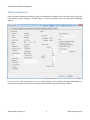
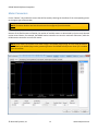
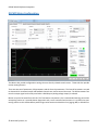
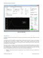
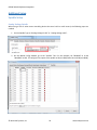
DSPMC Mach4 Software Integration Offset - Sets a constant bias to the PID output. This is useful to cancel any offset output voltage on the DSPMC analog output channels (J2, DAC 0 – 7). Velocity Feed Forward – This value bypasses the PID filter and directly applies an increase to the Analog Voltage output. Low Pass Filter – This field is used to smooth the analog output so the motors run smooth and less noisy. As the PID runs at 5 KHz, a value of 5 will create a nice linearly increasing DAC output at 1 KHz. If you put a value of 10, effective PID speed will become 500 Hz. More information on other PID terms and general discussion on PID control is available at: http://en.wikipedia.org/wiki/PID_control. PID Tuning Steps 1. Set “P” to 100, “Max Follow Error” at 5000, low pass at 5. Set all other parameters to zero. 2. Do test motion commands with very high acceleration and velocity settings, but over a small position such as 0.1 units. (Refer to the Test Motion Section) 3. If no motion is observed, start increasing “P” until you do see motion. Check the Response graph for details on the motion. 4. If the actual position moves is in the opposite direction of commanded, change the encoder polarity in the system tab. 5. Once you get a decent graph, (i.e. actual position follows commanded), start adding “I”, “Max Error I”, “D” and “Velocity Feed Forward” terms to fine tune the graph. NOTE: When you set the “I” term greater than 0, make sure “Max Error I” is also non-zero, otherwise you will get uncontrolled oscillations, (e.g. start “I” with 5 and “MaxError I” as 100, and gradually increase or decrease). 6. Ideally, the actual graph line should be as close to commanded as possible. Do the test motions for small and large moves, i.e. few mm to 100 of mms. © 2014 Vital Systems, Inc. 20 www.vitalsystem.com