1
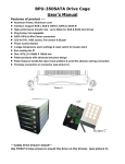
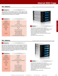
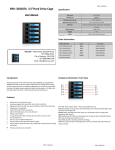
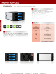
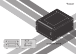
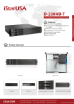
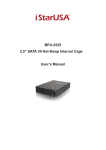
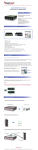
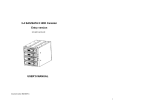
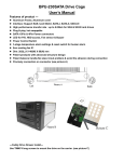
BPU-350SATA BPU-350SATA 3.5”Hard Drive Cage User’s Manual Specification: Hot Swap 5x3.5”HDD Cooling Fan 1x80mm Standard Drive Bays 5.25” Drive: 3 Dimension (W x H x D) 5.75 x 4.96 x 8.11 inches Material Aluminum Design with Conductive Dissipation HDD Interface SATA / SAS Grooves Weight 4bs Cable SATA Cable Included (5pcs) Order Information: iStarUSA – Powered by iStarUSA Group 727 Phillips Drive City of Industry, CA 91748 Tel: (888) 989-1189 Email: [email protected] Introduction: Model Number: Color: UPC Code: BPU-350SATA-BLACK Black 846813022606 BPU-350SATA-RED Red 846813000604 BPU-350SATA-BLUE Blue 846813000598 BPU-350SATA-SILVER Silver 846813000611 BPU-350SATA-BPL Plastic 846813016087 (lockable handle) Hardware Information: Front View Create more space for hard drive with hot-swap capability, by using the BPU350SATA HDD cage series that supports RAID 1/0/1+0/5 configuration for high performing data recovery or redundancy application. Its aluminum construction translates into lighter system weight and better heat dissipation. The 80mm fan also help keeps hard drives at maximum performance temperature. Features: Aluminum Frame, Aluminum cover Interface: Support SAS-I and SAS-II, SATA-I, SATA-II, SATA-III High performance transfer rate: up to 6.0 GB/s for SAS & SATA hard drives Plug & play, hot swappable SATA 15Pin & 4Pin Power connectors LED for P/S, HDD access, Fan sensor & Buzzer Power Control Switch 3-stage temperature alarm settings & reset switch for buzzer alarm 8cm cooling fan X1 Dim: 8.11(L) X 5.75(W) X 4.96(H) inch Patent products with advanced structure design Patent balance handle-No skew in/out problem & avoid the abrasion during connection Precisely connection on connector BPU-350SATA D-1 ~ D-5: Power Switch & HDD LED. Power On: LED indicates Blue. Purple color blinking for HDD access. D-6: Reset Switch & Overheat LED. Power On: LED indicates Blue. Overheat (default 55º C): LED indicate Red and buzzer alarms. Press the Reset Switch (D-6) to stop the alarm for 3 minutes. D-7: Fan senor LED. Fan On: LED indicates Blue. Fan Off: LED indicates Red and buzzer alarms. Press the Reset Switch (D-6) to stop the alarm. (If you want to switch off the “Alarm function”, press the Reset Switch (D-6) for more than 6 seconds until 3 beeps comes out, then the “Alarm function” stopped.) BPU-350SATA BPU-350SATA Hardware Information: Rear View BPU-350SATA Quick Installation Procedure: 1. 2. 3. 4. 5. 6. POWER1: 4pin Power connector. POWER2: 15pin Serial ATA Power connector. (may use any two type of power connector) HD1— HD5: 7pin Serial ATA Signal connector JP1: Temperature setting jumper (default: 55º C) J5: FAN RPM Switch: HIGH & AUTO Optional. (Every time when you turn on the power, the fan runs for 10 seconds and then stop. It will run again when temperature reaches 40º C.) J6: HD LED Switch (default: Enable) 7. Open up the handle bar from the tray; take out the HD trays from the HD cage. Secure all screws to the HD attached with HD tray. Place the hard drive tray(s) with HD installed, back into the cage unit. Push the handling bar into closed position. Connect all necessary data and power cable onto the rear end of cage unit. (Make sure that the date cables connected to the motherboard side as well). Turn on the Power of your computer and wait until Operating System finish loading up. Turn on all necessary HD1~HD4 Power Button(s) for each Hard Drive installed. Note: For steps 6- if the operating system installed with a HD inside of HD cage, please make sure you do turn on the Power from the cage switches D1/D2/D3/D4 or D5. For optional RAID Configuration & Setup procedure, please follow the user manual instructions from your SAS/SATA Controller Card or Motherboard. JP1 Jumper pin setting: Accessories: 2.5” or 3.5” Hard Drive Disk to the trays Installation: 1. 2. 3. 4. 5. Insert 2.5” or 3.5” Hard Drive into the HDD Tray from the cage. Use the provided screws and fasten HD into highlighted 2.5” or 3.5” holes to the cage trays. Make sure Secure with screw holes from the Bottom of 2.5” or 3.5” Hard Drive’s. After the screw installation, slide the HDD Tray back to the HDD Canister Base. Next, follow the Quick Installation in next page for the rest of the Setup. 5 SATA cables Screws Optional Accessories: HD Trays Black Model Number UPC Code: BPU-HSTRAY-BLACK 846813000635 Red BPU-HSTRAY-RED 846813000659 Blue BPU-HSTRAY-BLUE 846813000642 Silver BPU-HSTRAY-SILVER 846813000673 Plastic BPU-HSTRAY 846813000628 iStarUSAcare: We will help you navigate our website to find the information that you need. Go to www.istarusa.com, and click on live chat bubble above the Search Bar 3.5” HD Screw Holes 2.5” HD Screw Holes Our technicians are standing by to take your questions. Visit http://istarusa.com/support/ , and you will receive a technical support ticket to help track your requests from the beginning to the end. Or you can contact us @ 888-989-1189 HD Tray: Bottom View 3.5” HD Screw Holes FCC and CE Radiation Norm FCC This equipment has been tested and found to comply with limits for Class B digital device pursuant to Part 15 of Federal Communications Commission (FCC) rules. CE This equipment has been tested and found to comply with the limits of the European Council Directive on the approximation of the law of the member states relating to electromagnetic compatibility (89/336/EEC) according to EN 55022 Class B. FCC and CE Compliance Statement These limits are designed to provide reasonable protection against frequency interference in residential installation. This equipment generates uses and can radiate radio frequency energy, and if not installed or used in accordance with the instructions may cause harmful interference to radio communication. However, there is no guarantee that interference will not occur in television reception, which can be determined by turning the equipment off and on. The user is encouraged to try and correct the interference by one or more of the following measures: Reorient or relocate the receiving antenna, Increase the separation between the equipment and the receiver, connect the equipment into an outlet on a circuit different from that to which the receiver is connected to. CAUTION! The Federal Communications Commission warns the user that changes or modifications to the unit not expressly approved by the party responsible for the compliance could void the user’s authority to operate the equipment. BPU-350ATA BPU-350SATA