1
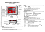
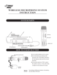
MC-12 Quick Reference 1.03.GB.00
General
Operation software version V1.03 production date 08-2006
Connect motor before switching on the controller
Part 1: Operation Reference
ALL changes
For more detailed information please consult the installation reference or User Manual
has to be entered
to acknowledge.
Start up
Input LED
The MC-12 software version is displayed shortly when the unit is switched on followed by the configuration mode (con).
Input LED is lighted when
input signal is made.
Configuration
Type of Production
Input signal
1
Injection Molding
Timer
2
Extrusion
Relay
is deactivated.
When the MC-12 is set to configuration 2, the time function key
When a deactivated keys is pushed the unit will give a beeping signal.
For changing the unit configuration please consult the complete manual
Increase / Decrease value
Alarm LED
Speed
and Timer
Speed and dosing time can be altered (time only in case of injection molding)
Enter value
Speed
= rotation of dosing system in RPM, 0,1 to 200 RPM)
Timer
= time dosing system will rotate after start impulse, at input cable (0,1 to 999,9 sec)
Activate by pressing
or
, set the desired speed or time using
press enter
to acknowledge
Set dosing speed [RPM]
Test
Run test
(Material output), can only be used when unit is stopped
Test procedure to determine output of dosing system:
Place dosing unit at water level surface. Î Set the speed (and or) time (see settings) Î Press
dosed during test Î Adjust speed or time and
Set dosing time [sec.]
Note:
(Configuration 1):
(Configuration 2):
repeat
for Test Î Weigh the material
Test if necessary.
The unit will dose with the set speed and time.
The unit will dose for 30 seconds at the set speed
Production (Motor On/Off)
Press
to start production. The function active LED will start blinking when the unit is waiting for an input signal.
The unit is dosing if the Start LED is lighted continuously.
- Start LED blinking:
Motor Standby / waiting on start signal.
Start unit
Stop unit
Alarms/ Warnings
Err0 :
- Start LED lighted continuously:
Motor is running.
Motor connection failure.
Make sure the motor is connected
Check cable and connectors
Press
Mains power switch On/Off
Input cable
Motor cable
Mains power cable
to stop the alarm.
MC-12 F.A.Q and Trouble shooting
Part 2: Installation Reference
General
The following variables may influence the accuracy and repeatability of the system:
For more detailed information please consult the User Manual
General information
1.
Use the equipment only for what it is designed for. The metering of dry additives!
2.
Before switching on the unit for the first time, ensure that the main power voltage being applied is set on the voltage selector at the
main power entry. (see: Electrical Installation)
3.
Always switch off the Movacolor control cabinet and disconnect from electrical power before performing maintenance.
4.
5.
symbol certifies that the machine conforms to the European Union regulations on minimum safety standards.
The
Make sure all parts are securely fixed to your extruder or injection molding machine.
To make the configuration available, keep
2.
The configuration number will be displayed, press
acknowledge. The software version will be displayed.
Configuration
and
pressed while switching on the main power.
to switch between the possible configuration and press
Type of Production
Input signal mode
1
Injection Molding
Timer
2
Extrusion
Relay
to
Timer
Timer mode is used for injection molding with a relay input signal. When the relay contact is made, the unit will start dosing according the
number of seconds that has been set with the time function.
Relay
A relay signal can be used incase working in extruder mode. With the relay input the unit will start dosing when the relay contact is made and
will stop when the relay is interrupted.
Electrical Installation
1.
Ensure right voltage is applied, the operation voltage can be manually selected inside the control cabinet, the controller has a voltage
sticker indicating the voltage setting.
2.
Input signal to the MC-12 can be made in the following 2 ways:
Potential free contact
9
10
+
IN
Potential contact
[min 18VDC to max 24VDC]
10
8
8
= Yellow
9
= Brown
10 = White
-
+
Mechanical installation
1.
2.
3.
All mechanical parts are pre-assembled, making installation quick and simple.
Install the neckpiece directly on top of the entrance of the production machine.
a.
Make sure that the complete unit is mounted horizontally leveled (water level) and fixed securely.
b.
Assure proper grounding to control cabinet, neckpiece and dosing unit
Connect the unit to the neckpiece by closing curled knob clockwise.
Mount the unit
in a 90-degree
angle to the
machine
barrel.
2.
3.
4.
Material properties. Easy flowing, non-sticky and non-static material that comes in the form of small regular shaped granules or
powder can be dosed very accurate and regular.
Periodical cleaning of the dosing cylinder and seals is necessary for proper operation.
Extreme vibrations and shocks can have negative influence on system performance.
Vacuum or overpressure in the neckpiece caused by driers or hopper loaders.
With injection moulding the shot to shot accuracy depends, besides the variables mentioned so far, on the shot time in combination with
granule size and weight. If relatively big and heavy granules have to be dosed in a very short time, it will influence the shot accuracy and
repeatability, because if only a few granules are dosed during the shot, one granule more or less makes a big difference on the total shot
weight.
Configuration
1.
1.
Neckpiece
As showen in
the picture.
Horizontally leveled
(Water level)
System is NOT starting up when switched ON by mains power switch
1.
Mains fuse inside the controller can be blown
Color variations
1.
Unstable relay signal.
2.
Bridging or rat holing of the material inside the hopper can happen if the material is not free flowing.
3.
Bridging or rat holing of the material inside the hopper can happen if the material is extremely static.
4.
Extremely static material can contaminate the dosing cylinder.
5.
In case of water cooled neckpiece, check if there is material build up around the dosing cylinder and the water cooled pipe. Check also
the water supply to the neckpiece.