1
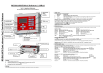
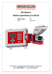
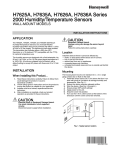
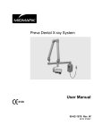
MC-12
User Manual 1.05.UK.01
Software version
Manual revision
Date
:
:
:
V1.05
01
September 2009
Movacolor B.V • Koperslagersstraat 31• 8601 WL Sneek • The Netherlands
Internet: www.movacolor.com • Email: [email protected]
+ 31 (0) 515 570020
+ 31 (0) 515 570021
1
INDEX
INDEX _____________________________________________________________________________________________________ 2
1. Introduction ______________________________________________________________________________________________ 3
Symbols: _________________________________________________________________________________________________ 3
Terms: ___________________________________________________________________________________________________ 3
2. General information________________________________________________________________________________________ 4
2.1 Safety ________________________________________________________________________________________________ 4
2.2 Certification ____________________________________________________________________________________________ 4
2.3 Operating environmental conditions _________________________________________________________________________ 4
3. Overview Dosing unit ______________________________________________________________________________________ 5
3.1 MC-12 Components overview. _____________________________________________________________________________ 5
3.2 Motor and dosing system. _________________________________________________________________________________ 5
3.3 Neckpiece_____________________________________________________________________________________________ 6
4. Metering principle _________________________________________________________________________________________ 7
5. Dosing systems / Capacities ________________________________________________________________________________ 8
6. Installation ______________________________________________________________________________________________ 10
6.1 Transport _____________________________________________________________________________________________ 10
6.2 Receipt ______________________________________________________________________________________________ 10
6.3 Mechanical Installation __________________________________________________________________________________ 10
6.4 Changing from Dosing cylinder to Feed screw ________________________________________________________________ 11
6.5 Electrical Connections___________________________________________________________________________________ 12
7. Operation _______________________________________________________________________________________________ 13
7.1 The Interface __________________________________________________________________________________________ 13
7.2 General ______________________________________________________________________________________________ 13
7.3 Start up ______________________________________________________________________________________________ 14
7.4 Configuration __________________________________________________________________________________________ 14
7.5 Speed
and Timer
_________________________________________________________________________________ 14
7.6 Production (Motor On/Off)
7.7 Test
__________________________________________________________________________ 15
(Material output), can only be used when unit is stopped
______________________________________________ 15
7.8 Alarms / Warnings ______________________________________________________________________________________ 15
7.9 Keyboard lock _________________________________________________________________________________________ 15
8. System performance ______________________________________________________________________________________ 16
APPENDIX A:
MC-12 Wiring Diagram _______________________________________________________________________ 17
APPENDIX B:
MC-12 Technical Specifications _______________________________________________________________ 18
APPENDIX C:
MC-12 General dimensions ___________________________________________________________________ 19
APPENDIX D:
MC-12 Declaration of Conformity ______________________________________________________________ 20
2
1. Introduction
Thank you for purchasing a Movacolor metering device. This manual is addressed to operators
and qualified technicians taking care of the metering of dry additives to ensure correct use of the
Movacolor dosing unit.
IMPORTANT NOTE: THIS MANUAL MUST BE READ BEFORE INSTALLING THE DOSING
UNIT. KEEP THIS MANUAL IN A PLACE ACCESSIBLE TO ALL OPERATORS.
Symbols:
Important note
Attention; safety regulations for the operator
Terms:
Operator:
A person charged to operate, adjust, maintain and clean the machine.
Qualified Technician:
A specialized, suitable trained person authorized to execute the
installation, non-routine maintenance, or repairs requiring special
knowledge of the machine and how it operates.
3
2. General information
2.1 Safety
The equipment is only designed and may only be used, for the dosing of dry additives.
Any use that does not conform to the instructions is considered improper and as such
releases the manufacturer from any liability in regard to damage to things and/or persons.
Always switch off the Movacolor control cabinet and disconnect from electrical power
before performing maintenance.
Ensure that all parts are securely fixed to the extruder or injection molding machine.
Dangerous voltages are present inside the control cabinet for up to 2 minutes after it has
been switched off.
2.2 Certification
•
•
•
•
•
The Movacolor dosing unit is designed and produced conform the following European
regulations:
standards for machinery (health, safety, environment)
EMC (electromagnetic compatibility)
VEM (safety electric material)
98/37/EC, Annex 1(See the declaration of conformity, Appendix C)
2.3 Operating environmental conditions
•
•
The unit must be protected against weather conditions
Operating temperature -20 to +70 degr. C.
4
3. Overview Dosing unit
3.1 MC-12 Components overview.
Hopper 6ltr
Standard NST40 Neckpiece
Dosing system (Dosing cylinder)
Stepper Motor
Slide valve (closed)
Slide valve (open)
MC-12 Controller
3.2 Motor and dosing system.
There are mainly two dosing systems, the dosing cylinder and the feed screw.
(for more information see chapter 5)
The serial number of the motor can be found on the
backside of the motor.
Motor axle:
The motor shaft is equipped with one flat side which
fits exact in shaft of the dosing cylinder.
To connect the dosing cylinder just put it on the
motor axle while turning it to find the flat side, than
press the dosing cylinder completely backwards.
5
3.3 Neckpiece
The NST40-Neckpiece is the standard neckpiece for the MC-12 . The window of the NST40
neckpiece can be dismounted for easy cleaning. Together with the window the insert is taken out.
Easy cleaning
Dismount only these 4 bolts.
Take out the window in a 45° angle.
6
4. Metering principle
The Dosing Cylinder® of Movacolor combined with a very precise adjustable stepping motor
ensures that the additive output is accurate and regular. For every particular application Movacolor
provides different neckpieces but the most common mounting of the neckpiece is between the
production machine and the hopper. In the figure below a cut through of the NST40 neckpiece can
be seen.
During operation, the virgin material runs from the
machine hopper through the neckpiece (1) into the
machine. Inside the neckpiece the virgin material flow (4)
is divided into two streams by the cover plate(3). In the
space below the cover plate, the rotating cylinder (2) is
dosing additive.
Additive is added directly into the center of the virgin
material flow, just before it enters the production
machine (5). This is a great advantage over metering devices
that use batch pre-mixing because pre-mixing can
actually cause material separation. Separation of
materials results in an irregular additive flow into the
production machine.
Fig. 3
1. Neckpiece 2. Dosing cylinder 3. Cover plate
4. Virgin material 5. To production machine
7
5. Dosing systems / Capacities
Depending on the application a different dosing system might be needed.
Use the following table to determine roughly the best system for the application. For more detailed
information please contact your agent or Movacolor.
Dosing system
GLX
GX
HX
A-20
Feed screw
Note *
Note **
Granular
materials
YES
YES
NO
YES
Powder
Materials
YES
YES
YES
YES
Accuracy
++
+
++
+/-
Dosing capacity
Gram/sec.
0,02 to 1,6*
0,2 to 5,0*
0,01 to 1,6**
0,5 to 20*
Dosing capacity
Kg/hour
0,07 to 5,8*
0,72 to 18,0*
0,04 to 5,8**
1,8 to 72*
measured with normal granular masterbatch 0,8 kg/dm3.
measured with free flowing powder 0,65 kg/dm3.
Front side view
GLX
GX
HX
A20LT
Back side view
Which type of dosing system do I need with which neckpiece?
TYPE
CODE FOR STANDARD NECKPIECE
CODE FOR WATERCOOLED NECKPIECE
GLX
GLX
GLXC
GX
GX
GXC
HX
HX
HXC
A20LT A20
A20C
8
To determine the kind of material in your application use the description below.
Material types
Normal Granules:
(NG)
ø
L
Ø<
Micro / Mini Granules:
(MG)
4 mm
L < 4 mm *
ø
L
The term Micro/Mini Granules also
includes free flowing powder.
Ø < ø2,5 mm L < 3 mm *
* For other sizes contact Movacolor.
The actual capacity of the dosing system depends on:
• The volume weight of the material (bulk density)
• The specific weight of the material (specific density)
• The granular shape of the material
• The granule size
• The surface structure of the material
Granular material can be normal or micro. The granular material and powder material has to be
free flowing, non-static and not sticky.
9
6. Installation
6.1 Transport
To protect the Movacolor unit against damage during transport, the unit is packed in a cardboard
box filled with polyurethane foam. In the event of damage to the unit, please contact your local
agent or Movacolor immediately. Delivery terms are Ex-Works Sneek, The Netherlands. Buyer is
responsible for the transport. Movacolor cannot be hold liable for any damage during transport.
6.2 Receipt
Check the unit thoroughly upon receipt. Pass any remarks to the local agent or Movacolor within 8
days upon receipt of goods.
6.3 Mechanical Installation
1. All mechanical parts are pre-assembled, making installation quick and simple.
2. Install the neckpiece directly on top of the entrance of the production machine.
a. Make sure that the complete unit is mounted horizontally leveled and fixed securely.
b. Assure proper grounding to control cabinet, neckpiece and dosing unit
3. Connect the unit to the neckpiece by closing curled knob clockwise.
Neckpiece
Horizontally leveled
(Water level)
Mount the unit in a 90-degree
angle to the machine barrel.
As shown in the picture.
10
6.4 Changing from Dosing cylinder to Feed screw
In relation to the maximum capacity of the dosing cylinder it might be necessary to change from
dosing cylinder to feed screw. As distinction from the dosing cylinder the feed screw system is
consisting of a rotating screw in a non-rotating tube.
3
1
2
4
To install the feed screw perform to following steps:
1. Detach the motor quick release clamps and take out the motor from the hopper.
2. Dismount the neckpiece connection flange (1) by removing 4 socket-head screws.
3. For use with a dosing cylinder the neckpiece connection flange (1) is equipped with a ball
bearing. When using a feed screw system the ball bearing must be taken out. The metal ring
(2) which is fixed on the feed screw tube fits directly on the neckpiece connection flange.
4. Dismount the dosing cylinder (3) and mount the screw (4) with the M5 bolt.
5. Place back the motor + screw by closing the motor quick release clamps.
For cleaning the motor + screw can be easily be taken out.
POSSIBLE COMBINATIONS
A20
GX / GLX / HX
Art.nr:H000002
Art.nr:H000014
Included ball bearing
G / GL / H
Art.nr:H000010
Included seal
BALL BEARING
For cleaning of the ball bearing use a dry piece of textile or a smooth dry toothbrush to remove the dust
or moisture and foreign particles that stick.
Following points have effect on the lifetime of the ball bearing:
o Abrasive materials / Temperature / Dusty / fine powder materials
11
6.5 Electrical Connections
The MC-12 needs an input signal from the production machine in order to operate.
Two different input signals can be used to control the MC-12.
1. A potential free relay contact.
Use the white and brown wire for the potential free contact.
2. A relay signal up to 24 Volt DC.
Relay signals can be used for an extruder that has not a tacho signal. In case of a powered
relay signal connect the white wire to +24 VDC and the yellow wire to - side.
See APPENDIX A for the wiring diagram.
12
7. Operation
7.1 The Interface
Input LED
Input LED is lighted
when input signal is
made.
Increase / Decrease
value
Alarm LED
Set dosing speed
[RPM]
Enter value
Run test
Set dosing time
[sec.]
- Start LED blinking:
Motor Standby / waiting on start signal.
Start unit
Stop unit
- Start LED lighted continuously:
Motor is running.
7.2 General
•
•
•
•
•
•
•
Connect motor before switching on the controller
ALL changes
has to be entered
to acknowledge.
A blinking value means the changed data is not entered.
To cancel a changed value, press the specific function button ( or ) again.
Most functions have a designated key and LED on the interface. When a function is
activated the LED of that key/function will light up.
All functions except the test function can be activated if the unit is started,
(dependent on the chosen configuration.)
Only one of the following functions , , can be active at the same time. This means no
other function can be activated before the active function is deactivated
The unit can be set to different configurations, see paragraph 7.4
13
7.3 Start up
The MC-12 software version is displayed shortly when the unit is switched on followed by the
configuration mode (con).
Configuration Type of Production
1
Injection Molding
2
Extrusion
Input signal
Timer
Relay
When the MC-12 is set to configuration 2, the time function key is deactivated.
When a deactivated keys is pushed the unit will give a beeping signal.
For changing the unit configuration see paragraph 7.4.
7.4 Configuration
To make the configuration available,
pressed while switching on the main power.
keep speed and enter
The configuration number will be displayed, press
to switch between the possible
configuration and press to acknowledge. The software version will be displayed.
Timer
Timer mode is used for injection molding with a relay input signal. When the relay contact is made,
the unit will start dosing according the number of seconds that has been set with the time function.
Relay
A relay signal can be used incase working in extruder mode. With the relay input the unit will start
dosing when the relay contact is made and will stop when the relay is interrupted.
7.5 Speed
and Timer
Speed and dosing time can be altered (time only in case of injection molding)
Speed
Timer
= rotation of dosing system in RPM, (0,1 to 200 RPM)
= time dosing system will rotate after start impulse, at input cable ( 0,1 to 999,9 sec)
Activate by pressing
acknowledge
or
, set the desired speed or time using
14
press enter
to
7.6 Production (Motor On/Off)
Press to start production. The function active LED will start blinking when the unit is waiting for
an input signal. The unit is dosing if the Start LED is lighted continuously.
7.7 Test
(Material output), can only be used when unit is stopped
Test procedure to determine output of dosing system:
Place dosing unit horizontally leveled (water level surface).
Set the speed (and or) time (see settings)
Press for Test
Weigh the material dosed during test
Adjust speed or time and repeat Test if necessary.
Note:
(Configuration 1):
(Configuration 2):
The unit will dose with the set speed and time.
The unit will dose for 30 seconds at the set speed
Emergency stop.
If the test is activated press stop
to cancel a test.
7.8 Alarms / Warnings
Err0 : Motor connection failure.
Make sure the motor is connected
Check cable and connectors
Press to stop the alarm.
7.9 Keyboard lock
+
+
= Lock / Unlock,
Display shows : L.ON / L.OFF
15
8. System performance
The following variables may influence the accuracy and repeatability of the system:
1. Material properties. Easy flowing, non-sticky and non-static material that comes in the form of
small regular shaped granules or powder can be dosed very accurate and regular.
2. Periodical cleaning of the dosing cylinder and seals is necessary for proper operation.
3. Extreme vibrations and shocks can have negative influence on system performance.
4. An unstable relay signal has a negative influence on the repeatability.
5. With injection molding the shot to shot accuracy depends, besides the variables mentioned so
far, on the shot time in combination with granule size and weight. If relatively big and heavy
granules have to be dosed in a very short time, it will influence the shot accuracy and
repeatability, because if only a few granules are dosed during the shot, one granule more or
less makes a big difference on the total shot weight.
6. Vacuum or overpressure in the neckpiece caused by driers or hopper loaders.
7. Bridging or rat holing of the material inside the hopper can happen if the material is not free
flowing.
8. Bridging or rat holing of the material inside the hopper can happen if the material is extremely
static.
9. Extremely static material can contaminate the dosing cylinder.
10. In case of water cooled neckpiece, check if there is material build up around the dosing
cylinder and the water cooled pipe. Check also the water supply to the neckpiece.
16
APPENDIX A: MC-12 Wiring Diagram
Input (start) signal
= White
Potential contact
[Min 18VDC to Max.24VDC]
White (4)
10
Green (3)
= Brown
Yellow (2)
Potential free contact
+
9
Brown (1)
-
= Yellow
7
6
5
4
Coil 1
Coil 2
Brown (L)
Black (L)
Black (N)
Internal wires
Main power switch
Blue (N)
IN
8
X5
X4
X2
X3
Power Supply
To open the control cabinet
Western Europe
use the 4 bolts on the top and
bottom side, not the 6 bolts at
the front side.
WARNING
Do not make any adaptation to
the main board/components
ore warranty will lapse.
17
PE
N
L
3
2
1
Brown
+
10
8
Blue
10
Green/Yellow
9
Motor
USA,Canada,Mexico,
Mid America,Japan,Taiwan
1 = Black
2 = White
3 = Green
APPENDIX B: MC-12 Technical Specifications
Controls:
Speed:
Time:
Manual setting from 0,1 to 200 RPM max, in increments of 0.1 RPM.
Manual settings from 0,1 to 999,9 sec in increments of 0,1 sec.
Monitoring/System Information/External communication
4-piece 7 segments LED at front display.
Man/Machine interface:
keypad
External Communication:
none
Alarm:
LED Indication + Internal beeper.
Specifications/Standards & Directives/ Technical data:
Power supply:
Operating power from 80 VAC to 260 VAC, 50 and 60 Hz
by integrated automatic voltage selector
Power consumption:
80 Watt maximum
Stepper motor:
(1,8degr/step) max 2 Amp at 40 Volt.
Operating Temperature:
-20 to +70 degr. C.
Input signal(s):
Injection molding:
Extrusion:
Start/Stop trigger input, potential free or 18-24VDC*
Start/Stop trigger input, potential free or 18-24VDC*
* Note potential contact
Guaranteed OFF: 0-8VDC
Guaranteed ON: 18-30VDC
Output(s):
Stepper motor max. output 2A (40VDC)
Standard Directives:
Protection class: IP-50
According to CE standards:
EN50081-2 (HF radiation industry)
EN50082-2 (HF immunity industry)
Safety
•
•
In case of overload due to short-circuit or in correct connection, the power supply automatically shuts down.
Opto insulated start input for connection to production machine.
Machine connection flange:
Standard flange NST40 neckpiece with cleaning opening.
Inlet/outlet ø50mm/ 40mm, steel epoxy coated
Optional parts
•
12 liter hopper stainless steel.
•
Flange type NST90 with cleaning opening and inlet/outlet Ø50mm/ 90mm, steel epoxy coated.
•
Water-cooled flange BH(A) inlet/outlet 50mm/50mm stainless steel ANSI 304.
•
Water-cooled flange PHA inlet/outlet 100mm/100mm
(See next page for technical drawing.)
18
APPENDIX C: MC-12 General dimensions
General dimensions MC-12 + NST40 neckpiece
19
APPENDIX D: MC-12 Declaration of Conformity
DECLARATION OF CONFORMITY
(According to 98/37/EC, Annex 1)
Manufacturer’s name
:
MOVACOLOR BV
Address
:
P.O. Box 3016
8600 DA Sneek
The Netherlands
Declare under our sole responsibility that the product:
Name
:
Movacolor
Model
:
MC-12
Year
:
200…..
Serial nr.
:
……………….
-
Complies with the definition of the Machine Directive (98/37/EC), and
complies with the national legislation to enforcement of this directive;
-
complies with the requirements of:
Low Voltage Directive
EMC Directive
-
(73/23/EEC)
(89/336/EEC)
complies with the following standards or other normative documents:
NEN-EN 292-1/2
Safety of machinery part 1 + 2
(Signature)
Place: Sneek the Netherlands
Managing Director
Date: September 29, 2009
20