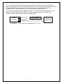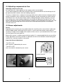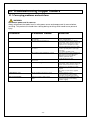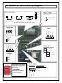
1
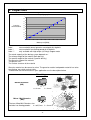
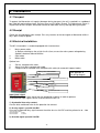
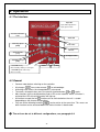
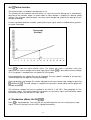
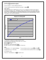
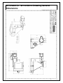
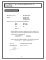
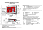
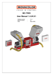
MC18-Micro
User manual 1.08.UK.00
Software Version
Manual Revision
Datum
:
:
:
V1.08 µ1.00
00
June 2011
Movacolor B.V • Koperslagersstraat 31• 8601 WL Sneek • The Netherlands
Internet: www.movacolor.com • Email: [email protected]
+ 31 (0) 515 570020
+ 31 (0) 515 570021
INDEX
INDEX _____________________________________________________________________________________________________ 3
1. Introduction ______________________________________________________________________________________________ 2
2. General information ________________________________________________________________________________________ 3
2.1 Safety ________________________________________________________________________________________________ 3
2.2 Certification ____________________________________________________________________________________________ 3
2.3 Operating environmental conditions _________________________________________________________________________ 3
3. Capacities ________________________________________________________________________________________________ 4
4. Installation _______________________________________________________________________________________________ 5
4.1 Transport ______________________________________________________________________________________________ 5
4.2 Receipt _______________________________________________________________________________________________ 5
5. Installation hopper loader (optional) __________________________________________________________________________ 7
5.1 Mechanical installation ___________________________________________________________________________________ 7
5.2 Compressed air installation ________________________________________________________________________________ 7
5.3 Connecting material line __________________________________________________________________________________ 7
5.4 Adjusting compressed air flow______________________________________________________________________________ 8
5.5 Sensor adjustments ______________________________________________________________________________________ 8
6. Operation ________________________________________________________________________________________________ 9
6.1 The Interface ___________________________________________________________________________________________ 9
6.2 General _______________________________________________________________________________________________ 9
6.3 Start up ______________________________________________________________________________________________ 10
6.4 Configuration __________________________________________________________________________________________ 10
6.5 Speed
6.6
and timer
Tacho function _____________________________________________________________________________________ 11
6.7 Production (Motor On/Off)
6.8 Test
6.9
________________________________________________________________________________ 10
________________________________________________________________________ 11
(material output) ________________________________________________________________________________ 12
Automatic hopper loaders (optional) ____________________________________________________________________ 13
6.10 Keyboard lock _______________________________________________________________________________________ 14
7. Alarms __________________________________________________________________________________________________ 15
7.1 General ______________________________________________________________________________________________ 15
7.2 Filling alarm [FILA] (optional) _____________________________________________________________________________ 15
7.3 Motor connection failure [Err0] ____________________________________________________________________________ 15
8. System performance ______________________________________________________________________________________ 16
9. Maintenance (hopper loaders) ______________________________________________________________________________ 17
9.1 Preventative maintenance schedule ________________________________________________________________________ 17
10. Troubleshooting hopper loaders ___________________________________________________________________________ 18
10.1 Conveying problems and solutions. _______________________________________________________________________ 18
APPENDIX A:
MC-18 Wiring Diagram _______________________________________________________________________ 19
APPENDIX B:
MC18-Micro Technical Specifications __________________________________________________________ 20
APPENDIX C:
MC18-Micro Technical Specifications Hopper loaders_____________________________________________ 21
APPENDIX D:
MC18-Micro Drawing General Dimensions ______________________________________________________ 22
APPENDIX E:
MC18-Micro Declaration of Conformity _________________________________________________________ 23
1. Introduction
Thank you for purchasing a Movacolor metering device. This manual is addressed to operators
and qualified technicians taking care of the metering of dry additives to ensure correct use of the
Movacolor dosing unit.
IMPORTANT NOTE: THIS MANUAL MUST BE READ BEFORE INSTALLING THE DOSING
UNIT. KEEP THIS MANUAL IN A PLACE ACCESSIBLE FOR ALL OPERATORS.
1.1 Symbols
Important note
Attention; safety regulations for the operator
1.2 Terms
Operator:
A person charged to operate, adjust, maintain and clean the machine.
Qualified Technician:
A specialized, suitable trained person authorized to execute the
installation, non-routine maintenance, or repairs requiring special
knowledge of the machine and how it operates.
-2-
2. General information
2.1 Safety
The equipment is only designed and may only be used for the dosing of dry additives.
Any use that does not conform to the instructions is considered improper and as such
releases the manufacturer from any liability in regard to damage to things and/or persons.
Before switching on the unit for the first time, ensure that the mains power voltage
applied is between 80 and 260Vac.
Always switch off the Movacolor control cabinet and disconnect the mains power plug from
electrical power before performing maintenance.
Ensure that all parts are securely fixed to the extruder or injection molding machine.
Dangerous voltages are present inside the control cabinet for up to 2 minutes after it has
been switched off.
2.2 Certification
The Movacolor dosing unit is designed and produced in conformity with the following European
regulations:
•
standards for machinery (health, safety, environment)
• EMC (electromagnetic compatibility)
• VEM (safety electric material)
• 98/37/EC, Annex 1(See the declaration of conformity, Appendix E)
2.3 Operating environmental conditions
•
•
•
The unit must be protected against weather conditions
Operating temperature -20 to +70 degr. C.
Protection class: IP-50
-3-
3. Capacities
Capacity graph
1
0,9
0,8
0,7
Capacity
Gram/Second
0,6
0,5
0,4
0,3
0,2
0,1
0
0
20
40
60
80
100
120
140
160
180
200
Motorspeed [RPM]
Note *
Note **
Note ***
measured with normal granular masterbatch 0,8 kg/dm3.
measured with free flowing powder 0,65 kg/dm3.
only available with high torque (4,5 Amp) stepper motor
The actual capacity of the dosing system depends on:
The volume weight of the material (bulk density)
The specific weight of the material (specific density)
The granular shape of the material
The granule size
The surface structure of the material
Granular material can be normal or micro. The granular material and powder material has to be
free flowing, non-static and not sticky.
To determine the kind of material in your application use the description below.
Material types
Normal Granules:
(NG)
ø
L
Ø<
Micro / Mini Granules:
(MG)
4 mm
L < 4 mm *
ø
L
The term Micro/Mini Granules also
includes free flowing powder.
Ø < ø2,5 mm L < 3 mm *
-4-
4. Installation
4.1 Transport
To protect the Movacolor unit against damage during transport, the unit is packed in a cardboard
box filled with polyurethane foam. Delivery terms are Ex-Works Sneek, The Netherlands. Buyer is
responsible for the transport. Movacolor cannot be hold liable for any damage during transport.
4.2 Receipt
Check the unit thoroughly upon receipt. Pass any remarks to the local agent or Movacolor within 8
days upon receipt of goods.
4.3 Electrical installation.
The MC-18 controller is standard equipped with 3 connections:
1.
2.
3.
Mains power cable,
Before switching on the unit for the first time, ensure the mains power voltage being
applied is between 80 and 260Vac.
Input cable
Motor cable
Optional are:
4.
5.
6.
Sensor, complete with cable
Alarm flash light, complete with cable
Compressed air solenoid valve complete with cable (for automatic hopper loader)
Mains power switch On/Off
6.) Output 24VDC (hopper loader)
See appendix A
for wiring diagram
5.) External Alarm output 24VDC
4.) Sensor input 24VDC
3.) Motor cable
2.) Input (see installation)
1.) Mains power cable
Input (start) signal
The MC-18 needs an input signal from the production machine in order to operate.
Three different input signals can be used to control the MC-18.
1.) A potential free relay contact.
Use the white and brown wire for the potential free contact.
2.) A relay signal up to 24 Volt DC*.
In case of a powered relay signal connect the white wire to +24 VDC and the yellow wire to - side.
* Note potential contact
Guaranteed OFF:
0-8VDC
Guaranteed ON:
18-30VDC
3.) A tacho signal up to 30 Volt DC.
-5-
This is used when the MC-18 needs to be connected to an extruder that has a generator that
produces a voltage linear to the extruder speed. When using a Tacho generator signal, connect the
white and brown wire, connect green to + VDC and yellow to - side of the generator. See
Paragraph 6.6 for information about the configuration of the tacho parameters.
The maximum voltage that can be applied to the MC-18 is 30 VDC. The tacho voltage has to be
reduced to 30 VDC if the tacho generator has a higher voltage output than 30 VDC at the
maximum extruder output capacity. See the diagram below.
Input
connection
Green wire +
Resistor (Rx)
kOhm
17
8
Yellow wire -
Rx (kilo-Ohm) = (2,684 x (Max. tacho output VDC – 5)) – 66
-6-
Tacho
generator
EXTRUDER
5. Installation hopper loader (optional)
5.1 Mechanical installation
The Hopper loader lid fits directly on the hopper of the dosing unit.
To fix the ME hopper lid the quick release clamps on the dosing hopper are used.
5.2 Compressed air installation
The ME-loader uses compressed air to move material. The inlet for your compressed
air supply line is on the solenoid valve. The air connection diagram can be found on the valve’s
body.
1. Connect the compressed air to the ø8x6 compressed air connection on the solenoid valve
The compressed air source must deliver a maximum of 4-8 bar of clean, dry (non-lubricated), air
pressure.
2 . Make connections from the solenoid and the ejector pipe with the provided compressed air
tubing. Quick disconnect fittings are provided for these connections. The tubing should be cut to
length for maximum efficiency of the system. Use straight cuts to assure a good square tubing end.
Confirm a good connection.
CAUTION:
Be sure to provide hazard-free routing of the tubing, to keep it away from hot or
moving surfaces and out of the way of personnel.
5.3 Connecting material line
The flexible hose need to be attached over the inlet pipe of the ME-hopper lid and ejector pipe.
Secure the hose with a hose clamp.
Reduce flex hose down to the shortest possible length, to avoid wasting compressed air energy.
IMPORTANT: The material line should be as straight as possible.
Avoid loops and S-curves in flexible hose This can hurt conveying
performance.
-7-
5.4 Adjusting compressed air flow
Adjusting compressed air flow
It is advised to use a flow regulator for the compressed air (not included).
The air flow will determine how much material will be transferred and how fast the dosing unit will
be replenished with material, with each loading sequence.
The best is to adjust the air setting to its lowest possible level in order to conserve compressed air
energy. Parameters such as distance, material line bends, the flow characteristics of the material
and vertical rises in the flex hose all play a part in finding the proper setting. Ultimately, trial and
error settings over several loading sequences will work best to determine the right air level. Too
low of a setting may not move material effectively enough to satisfy demands cycle after cycle. Too
much air will waste energy and cause the filter on the lid to prematurely blind in an attempt to
evacuate excess air.
5.5 Sensor adjustments
Sensor
Depending on the material you may need to adjust the sensitivity of the sensor which is delivered
with the hopper loader. At the back of the sensor is a small screw that can be used to adjust its
sensitivity. To adjust, fill the hopper with material until the sensor is just covered and turn the screw
until the light on the sensor goes on.
Because the sensor is in direct contact with the material, it is recommended that the sensor will be
initially adjusted for sensitivity and then re-adjusted, once the sensor becomes coated with typical
material fines, common to plastics conveying.
Capacitive Sensor Adjustment
-The LED is ON
when material is detected by the sensor.
-The LED is OFF
when no material is detected by the sensor.
Sensitivity adjustment
LED
More sensitive
Less sensitive
-8-
6. Operation
6.1 The Interface
Input LED
Input LED is lighted when
input signal is made.
Increase / Decrease
value
Alarm LED
Set dosing speed
[RPM]
Enter value
Run test
Set dosing time
[sec.]
Set hopper loader
Set Tacho voltage
[VDC]
- Start LED blinking:
Motor Standby / waiting on start signal.
Start unit
Stop unit
- Start LED lighted continuously:
Motor is running.
6.2 General
•
Connect motor before switching on the controller
•
•
All changes
have to be entered
to acknowledge.
A blinking value means the changed data is not entered.
•
•
To cancel a changed value, press the specific function button (
or
) again.
Most functions have a designated key and a LED on the interface. When a function is
activated the LED of that key/function will light up.
All functions except the test
function can be activated when the unit is started.
(depending on the chosen configuration.)
•
•
Only one of the following functions
, , can be active at the same time. This means no
other function can be activated before the active function is deactivated
The unit can be set to different configurations, see paragraph 6.4
-9-
6.3 Start up
The MC-18 software version is displayed shortly when the unit is switched on, followed by the
selected motor type Lo=Low Torque and HI=High Torque motor. After that the configuration mode
(CON) will be shown.
Configuration
1
2
3
4
5
6
Type of Production
Injection Molding
Injection Molding
Extrusion
Extrusion
Extrusion
Extrusion
Input signal
Timer
Timer
Relay
Tacho
Relay
Tacho
Hopper loader
none or ME (when connected)
none or MV (when connected)
none or ME (when connected)
none or ME (when connected)
none or MV (when connected)
none or MV (when connected)
When the MC-18 is set to configuration 3 to 6, the time function key
When a deactivated key is pushed the unit will give a beeping signal.
is deactivated.
6.4 Configuration
For changing the unit configuration,
and enter
pressed while switching on the main power.
keep speed
The configuration number will be displayed, press
to switch between the possible
configurations and press
to acknowledge. The software version will be displayed.
Configuration data is normally entered once and it remains the same for subsequent operation.
The data entered during configuration is saved in memory and remains in the memory even when
the unit is shut off or unplugged.
Timer
Timer mode is used for injection molding with a relay input signal. When the relay contact is made,
the unit will start dosing according the number of seconds that has been set with the time function.
Relay
A relay signal can be used when working in extruder mode. With the relay input the unit will start
dosing when the relay contact is made and will stop when the relay contact is interrupted.
6.5 Speed
and timer
Speed and dosing time can be altered (time only in case of injection molding)
Speed
Timer
= rotation of dosing system in RPM, (0,1 to 200 RPM)
= time dosing system will rotate after start impulse, at input cable ( 0,1 to 999,9 sec)
Activate by pressing
acknowledge
or
, set the desired speed or time using
- 10 -
press enter
to
6.6
Tacho function
The tacho function is available in configuration 4 & 6.
This function can be used with extrusion when it is necessary that the dosing rate is automatically
adjusted to the extruder speed. In tacho mode an input voltage is coupled to a dosing speed
setting. If the extruder speed changes, the tacho input voltage and speed of the dosing unit will
change accordingly.
A linear correlation between extruder speed (tacho input signal) and the needed dosing speed is
assumed. See graph.
Speed (RPM)
Tacho graph
(Example)
Tacho input voltage (VDC)
Press
to make the tacho function active. The display will show a numerical value that
represents the current voltage of the tacho input signal. When
(P1 in the graph) is coupled to the set speed (P2 in the graph).
is pressed the current voltage
During production, the speed (P2) can be changed. The new speed is coupled to the previous
stored voltage and the graph will change accordingly.
During production, the voltage (P1) can be adjusted to the current tacho input voltage by pressing
followed by
. The new voltage is coupled to the previous stored speed and the graph will
change accordingly.
The maximum voltage that can be applied to the MC-18 is 30 VDC. See paragraph 6.4 for
information about the correct electrical connections of the tacho signal and information about
connecting a higher then 30 Volt DC input signal.
6.7 Production (Motor On/Off)
Press
to start production. The start LED will start blinking when the unit is waiting for an input
signal. The unit is dosing if the start LED is lighted continuously.
- 11 -
6.8 Test
(material output)
The test function is used to calibrate the MC-18
The test function can only be used when the motor is stopped
.
How it works
Determine the dosing unit RPM entirely manual. This can be done by drawing up the dosing
characteristic manually, or by recording the relation of the RPM versus the system output in a
chart. With this multipoint chart, it is possible to determine the rpm that corresponds to the dose
amount. This must be repeated for every dosing setting because the dosing conditions and the
used materials are usually very different.
Manual made dosing graph
made at 3 sec dosing time
7
grams per shot
6
Output in gram
5
4
3
2
1
0
0
10
30
60
90
120
150
180
200
RPM
Test procedure to determine output of dosing system:
Place dosing unit horizontally leveled (water level surface).
Set the speed (and or) time
for Test
Press
Weigh the material dosed during test
Adjust speed or time and repeat
Test if necessary.
Note:
(Configuration 1 & 2 / Injection Molding):
(Configuration 3 to 6 / Extrusion):
Emergency stop.
If the test is activated press stop
The unit will dose at the set speed
and time
.
The unit will dose for 30 seconds at the set speed
to cancel a test.
- 12 -
6.9
Automatic hopper loaders (optional)
Hopper loader settings
This part of the manual describes how to make the hopper loader settings. For further technical
information about the hopper loader consult the specific hopper loader manual.
General
The hopper loader is only activated when the motor is On
Emergency stop.
To stop the hopper loader during production press
press
to acknowledge.
.
, select “Off” by pressing
or
and
Input signal (sensor)
Depending on the material you may need to adjust the sensitivity of the sensor which is delivered
with the hopper loader. At the back of the sensor is a small screw that can be used to adjust its
sensitivity. To adjust, fill the hopper with material and turn the screw until the light on the sensor
goes on.
Output signals
During fill time [FILt] there will be a 24VDC signal between connection 20 and 21 on the main
board to activate the pneumatic solenoid valve (See appendix A)
The hopper loader LED on the front of the controller indicates the status of the valve output.
When the Fill Alarm [FILA] is active there will be a 24VDC signal between connection 18 and 19 on
the main board to activate the flash light. (See appendix A).
The controller itself gives a beeping signal and the alarm LED will lighten up.
ME settings
Configuration 1, 3 and 4 (see paragraph 6.3 & 6.4)
Press
to change ME hopper loader settings,
the display will show in following order:
On / Off:
Press
to switch the ME-hopper loader On or Off and press
acknowledge.
FILt:
Fill time [sec.], during this time the system blows material into the hopper of the
dosing unit.
Press
to change the time and press
to acknowledge.
Recommended basic setting: 15 sec
FILA:
Fill Alarm [sec.], if sensor is NOT covered within this time, the alarm starts.
Press
to change the time and press
to acknowledge.
Recommended basic setting: 30 sec
- 13 -
to
6.10 Keyboard lock
+
+
= Lock / Unlock,
Display shows : L.ON / L.OFF
- 14 -
7. Alarms
7.1 General
To cancel an alarm press enter
.
When an alarm is active there will be a 24VDC signal between connection 18 and 19 on the main
board to activate the flash light. (See appendix A).
The controller itself gives a beeping signal and the alarm LED will lighten up.
7.2 Filling alarm [FILA] (optional)
The MC-18 is able to give an alarm when there is not sufficient material inside the hopper.
Alarm settings when using a automatic hopper loader.
See paragraph 6.9
Alarm settings manual hopper filling (without automatic hopper loader)
In case of manual filling of the hopper, the hopper loader control of the MC-18 is used to generate
the filling alarm. A sensor and an alarm output is needed.
Use the settings below.
ME:
ME hopper loader = ON
FILt
FILA
= 0,1
= 0,2
The Filling alarm is self eliminating,
this means that the alarm will stop automatically when the sensor is covered with material.
If an alarm is canceled by pressing enter
the next alarm will come (if the sensor is still not
covered) with a delay of 60 seconds. This gives the operator the time to manual fill the hopper
without having the alarm on.
7.3 Motor connection failure [Err0]
Err0 : Motor connection failure.
Make sure the motor is connected
Check cable and connectors for damage.
Press enter
to stop the alarm.
When the MC-Micro unit is supplied excluding dosing unit (only hopperloader, no dosing motor)
[Err0] is disabled (Jumper 1 “JP1” on the Mainboard is placed in the “OFF” position.)
This jumper is located on at the upper right side of the Mainboard. To activate the motor alarm
[Err0], jumper 1 must be placed in the ON position.
- 15 -
8. System performance
The following variables may influence the accuracy and repeatability of the system:
1. Material properties. Easy flowing, non-sticky and non-static material that comes in the form of
small regular shaped granules or powder can be dosed very accurate and regular.
2. Periodical cleaning of the dosing cylinder and seals is necessary for proper operation.
3. Extreme vibrations and shocks can have negative influence on system performance.
4. An unstable relay signal has a negative influence on the repeatability.
5. With injection molding the shot to shot accuracy depends, besides the variables mentioned so
far, on the shot time in combination with granule size and weight. If relatively big and heavy
granules have to be dosed in a very short time, it will influence the shot accuracy and
repeatability, because if only a few granules are dosed during the shot, one granule more or
less makes a big difference on the total shot weight.
6. Vacuum or overpressure in the neckpiece caused by driers or hopper loaders.
7. Bridging or rat holing of the material inside the hopper can happen if the material is not free
flowing.
8. Bridging or rat holing of the material inside the hopper can happen if the material is extremely
static.
9. Extremely static material can contaminate the dosing cylinder.
10. In case of water cooled neckpiece, check if there is material build up around the dosing
cylinder and the water cooled pipe. Check also the water supply to the neckpiece.
- 16 -
9. Maintenance (hopper loaders)
9.1 Preventative maintenance schedule
• Daily
Clean the conveying filter.
If you are running a dusty material or regrind you may need to check and
clean the filter more often. The filter should be cleaned whenever you
change materials.
- 17 -
10. Troubleshooting hopper loaders
10.1 Conveying problems and solutions.
WARNING:
Disconnect power and air sources.
Always disconnect the loader from its main power source and compressed air course before
servicing. This prevents the loader from starting during servicing, which could cause personal
injury.
Problem
Possible cause
Solution
Low or no material flow.
Does the filter need to
be cleaned?
Are there kinks in the flex hose?
Check the filter, if it is clogged with dust
or fines, clean the filter.
Check the material flex hose line for
loops and “S” curves. Remove any loops
and “S” curves in the flex hose. Try to
keep the hose as straight as possible.
Check the material line for holes, cracks
Check the material line hose connections
for leaks especially at the ejector pipe
connection.
Hose clamps should be used.
Check the compressed air adjustment to
make sure it is properly adjusted for
optimum flow. Too much air will
prematurely blind the filter;
too little air will create clogs.
Replace/refill the material container
Are hose connections
too loose?
Are compressed air adjustments correct?
Do you have enough material at
the source?
Has material plugged the flexible hose?
Is the compressed air tubing connected?
Loader will not cycle.
Are all electrical connections correct?
Filter clogs frequently.
Is there too much compressed air
flow?
- 18 -
Check the material flex hose line for
loops and “S” curves. Remove any loops
and “S” curves in the flex hose. Try to
keep the hose as straight as possible.
Assure that the ejector pipe (s) are
supplied
with compressed air via the supplied
tubing.
Check to make the sensor
is connected to the control and the
solenoid is connected to the control.
Adjust the air flow to minimum possible
level to prevent excessive dusting
and filter clogging.
APPENDIX A: MC-18 Wiring Diagram
Input (start) signal
9
10
+
IN
10
8
8
9
10
-
17
8
= Yellow
Jumper settings
9
= Brown
To switch from stepper motor 2A to
stepper motor 4,5A
10 = White
+
ON
Stepper motor 4,5A
17 = Green
-
+
Stepper motor 2 A
OFF
Potential free contact
JP2
Tacho
Potential contact
[Min 18VDC to Max.24VDC] [Min 0VDC to Max. 30VDC]
Sensor input
(24VDC) INP2
12
= Blue
= Brown
13
= White
7
6
5
4
Alarm (+)
Valve (-)
Valve (+)
Coil 1
Alarm (-)
11
White (4)
Capacity
sensor
Green (3)
13
Yellow (2)
12
+24VDC Inp.2
Brown (1)
11
Gnd
Motor
18
19
20
21
Output
1
Internal wires
main power switch
X5
Blue (N)
X4
Brown (L)
Output
2
Outputs
[ 24 VDC]
= White
21
= Brown
To open the control cabinet
use the 4 bolds on the top and
bottom side, not the 6 bolds at
the front side.
WARNING
Do not make any changes to
the main board/components
ore warranty will lapse.
Power Supply
Western Europe
PE
N
L
3
2
1
Brown
= Brown
20
Blue
= White
19
Green/Yellow
18
Coil 2
- 19 -
USA,Canada,Mexico,
Mid America,Japan,Taiwan
1 = Black
2 = White
3 = Green
X3
Black (N)
X2
Black (L)
APPENDIX B: MC18-Micro Technical
Specifications
Controls:
Speed:
Time:
Manual setting from 0,1 to 200 RPM max, in increments of 0,1 RPM.
Manual settings from 0,1 to 999,9 sec in increments of 0,1 sec.
Voltage settings of tacho-voltage: auto-detect
Integrated hopper loader controller
Monitoring/System Information/External communication
4-piece 7 segments LED at front display.
Man/Machine interface:
keypad
External Communication:
none
Alarm:
LED Indication + Internal beeper, 1x external alarm output.
Specifications/Standards & Directives/ Technical data:
Power supply:
Operating power from 80 VAC to 260 VAC, 50 and 60 Hz
by integrated automatic voltage selector
Power consumption:
80 Watt maximum
Stepper motor:
(1,8degr/step) max 2 Amp at 40 Volt.
Operating Temperature:
-20 to +70 degr. C.
Input signal(s):
Injection molding:
Extrusion:
Start/Stop trigger input, potential free or 18-24VDC*
Input for level sensor.
Start/Stop trigger input, potential free or 18-24VDC*
Tacho input 0..30VDC
Input for level sensor.
* Note potential contact
Guaranteed OFF: 0-8VDC
Guaranteed ON: 18-30VDC
Output(s):
-Stepper motor max. output 2A (40VDC)
-Solid state 24VDC/0.5 A output for valve hopper loader
-Solid state 24VDC/0.5 A output for external alarm
-Maximum total output power: 12 Watt (Valve output + alarm output)
Standard Directives:
Protection class: IP-50
According to CE standards:
EN50081-2 (HF radiation industry)
EN50082-2 (HF immunity industry)
Safety
•
•
In case of overload due to short-circuit or in correct connection, the power supply automatically shuts down.
Opto insulated start input for connection to production machine.
Optional parts
•
External Alarm Flash light.
•
External Alarm Siren.
- 20 -
APPENDIX C: MC18-Micro Technical
Specifications Hopper loaders
Loader model
Maximum capacity* with 1,8 ltr hopper
Maximum Capacity* (value mentioned only for reference)
Standard conveying distance
Material hose
Compressed air hose
Compressed air requirements
Consumption
Filter type
Additional Filter Cloth for fine dust.
ME25 (For normal granules and small regrind)
15 kg/h ( based on 10 seconds ON time and 3 minutes OFF time)
175 kg/h (at continuous working)
3 mtr
Ø25mm (inside diameter)
PVC hose with antistatic wire.
Maximum temperature 60°C
Ø6x1mm, outside ø8mm
4 to 8bar
0,25 to 0,45 m3/min.
Stainless steel Perforated plate, hole size ø2mm.
Filter cloth 120x120x12mm, EN779 classification G4
* The capacities are measured with normal granules with a bulk density of ~0,8 kg/dm3. Granule size 3-4 mm.
De mentioned capacities are orientation values because capacity depends on material properties.
- 21 -
APPENDIX D: MC18-Micro Drawing General
Dimensions
- 22 -
APPENDIX E: MC18-Micro Declaration of
Conformity
DECLARATION OF CONFORMITY
(According to 98/37/EC, Annex 1)
Manufacturer’s name
:
MOVACOLOR BV
Address
:
P.O. Box 3016
8600 DA Sneek
The Netherlands
Declare under our sole responsibility that the product:
Name
:
Movacolor
Model
:
MC-18-Micro
Year
:
20…..
Serial nr.
:
……………….
-
Complies with the definition of the Machine Directive (98/37/EC), and
complies with the national legislation to enforcement of this directive;
-
complies with the requirements of:
Low Voltage Directive
EMC Directive
-
(73/23/EEC)
(89/336/EEC)
complies with the following standards or other normative documents:
NEN-EN 292-1/2
Safety of machinery part 1 + 2
(Signature)
Place: Sneek the Netherlands
Managing Director
Date: June 16, 2011
- 23 -
- 24 -