1
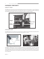
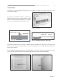
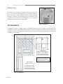
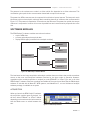
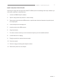
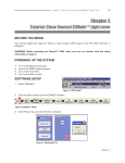
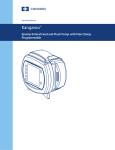
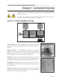
Chapter 1 • Instrument Overview
1
Chapter 1 • Instrument Overview
WARNING: Before operating the Nano-R™ AFM, make sure you are familiar with the safety
information on page iv.
CAUTION: To prevent damage to your instrument, probe, and sample, observe all the caution
statements in the tutorial chapters (Chapter 2 and Chapter 3).
NANO-R™ AFM INSTRUMENT SYSTEM
Video
Microscope
Monitor
Computer
Monitor
Master
Computer
Controller
(AFM Control
Electronics)
Trackball
Nano-R™
Stage
AFM Scaner
& Probe
Sample
Figure 1.1: Block Diagram of Nano-R Instrument System
Nano-R™ Stage - Includes the AFM scanner, probe, sample puck,
video optical microscope, and the AFM scanner’s real-time calibration
sensors.
Master Computer - The IBM PC-type computer is the virtual
interface to the Nano-R™ AFM stage. Pacific Nanotechnology
software programs resident on the computer’s hard disk are used
for measuring, visualization, and analysis of AFM images.
Controller - Contains most of the electronics required for operating
the Nano-R™ stage. It is connected to the Master Computer by a
standard Ethernet cable, and to the Nano-R™ stage by five cables.
Figure 1.2: Nano-R™ Stage
Video Monitor - Displays the optical microscope image of the probesample area. In some cases, the computer monitor may be used as
the video monitor.
Track ball - Provides an optional way to activate many of the motorized
features of the Nano-R™ stage, including the X-Y stage positioning
and the video microscope zoom and focus.
Figure 1.3: Controller
Revision 1.1
2
Nano-R™ AFM User Manual
HARDWARE COMPONENTS
NANO-R™ STAGE
The AFM scanner head rests on three motorized posts, which are used to perform a coarse Z approach
of the probe tip to the sample surface. The sample puck rests on a motorized X-Y stage for positioning
the sample under the probe. The puck can be easily removed for mounting a sample.
AFM Scanner
Head
Z Approach Motor
Motorized
X-Y Positioning
Sample Puck
Figure 1.4: Stage Components
AFM Scanner Head
The AFM Scanner Head contains the components that: 1: Measure the force between the probe and the
sample, and 2: Control the precise positioning of the probe in X, Y, and Z.
Detector Adjust Knobs
Laser Adjust Knobs
Laser
Photodetector
Cantilever
Figure 1.5: Light Lever Sensing System
Figure 1.6: Adjustment Knobs for Laser and Detector
The Nano-R™ AFM scanner uses both a light lever design and a crystal design. A red laser is focused
on the back of the cantilever and then projected onto a quad photodiode (photodetector). Two pairs of
manual adjustment knobs on the scanner head are used to align the sensing system. One pair controls
the position of the laser light on the backside of the cantilever; the other pair moves the photodetector
into the light path.
Revision 1.1
3
Chapter 1 • Instrument Overview
AFM PROBES
CAUTION: Use care when handling AFM probes, as they can break very easily. Always handle with tweezers, and
never touch the cantilever.
The Light Lever Nano-R™ AFM is shipped with
probes for the two basic imaging modes: contact
and close contact (vibrating cantilever). The probes
come in two marked boxes, 10 probes to a box.
Figure 1.7: AFM Probes
Cantilever & Probe
Cantilever Chip
Cantilever Chip
Cantilever
Metal Substrate
Metal Substrate
Figure 1.9: PNI AFM Probe (Side View -- Not to Scale)
Figure 1.8: PNI AFM Probe (Top View -- Not to Scale)
The probe tip extends from the end of a cantilever which is mounted to a chip (Figure 1.8). The metal
substrate that holds the cantilever chip is mounted in the AFM scanner; it is magnetically coupled to the
bottom of the scanner.
The two types of probes appear identical to the naked eye, but under the instrument’s optical microscope,
you can see that contact cantilevers are significantly longer than close contact cantilevers.
Figure 1.10: Contact Cantilever
Figure 1.11: Close-Contact Cantilever
Revision 1.1
4
Nano-R™ AFM User Manual
SAMPLE PUCK
The sample to be imaged is mounted on the sample puck. The
puck is composed of removable layers so the height of the puck
can be adjusted to accommodate different sample sizes (see
page 85 for details). The protruding piece on the bottom of the
puck fits into the groove on the X-Y stage so it can be safely and
easily guided into position under the probe.
Figure 1.12: Sample Puck
PNI REFERENCE
The Nano-R™ system is supplied with the PNI AFM reference, which is helpful for establishing the
performance of your instrument’s AFM scanners as well as the optical microscope. The reference also
serves as a useful test sample when learning how to use your instrument (the tutorials in this manual
are based on this sample).
14 mm
1 mm
10 mm
A
B
1 mm
C
D
AFM Reference
A: 1 micron square/2 micron pitch
B: 2.5 micron square/5 micron pitch
C: 5 micron square/10 micron pitch
D: 10 micron square/20 micron pitch
Notes:
- Feature height: nominal 75 nm
- Feature width: within +/- 0.3 microns
Optical Reference
(15 lines in each: a, b, c, d)
a b
c
d
Figure 1.13: PNI Reference
Revision 1.1
a: 1 micron line/2 micron pitch
b: 2.5 micron line/5 micron pitch
c: 5 micron line/10 micron pitch
d: 10 micron line/20 micron pitch
Chapter 1 • Instrument Overview
5
The patterns in the reference are made in a silicon nitride film deposited on a silicon substrate. This
combination gives optimal color contrast when viewed with an optical microscope.
The pattern for AFM measurements is composed of four blocks of square features. The features in each
block have uniform size and pitch, with each block containing features of a different size, as illustrated in
Figure 1.13. This pattern is repeated at 15 locations on the reference. The pattern for optical microscope
reference is composed of a series of four sets of parallel lines and a second series perpendicular to the
first.
SOFTWARE MODULES
The SPM Cockpit™ software modules serve three functions:
• acquire AFM data
• process and analyze the acquired data
• display AFM images (contained in the analysis modules)
EZMode™
Acquisition
X’Pert™
SPM Cockpit
PNI Analysis
Analysis
NanoRule+™
Figure 1.14: SPM Cockpit™ Software Modules
The interfaces for the image acquisition and analysis modules feature tool bars that provide convenient
access to the most commonly-used software functions for the given mode of operation. However,
regardless of the module (acquisition or analysis) or mode (EZMode™ or X’Pert™) you are in, all of the
SPM Cockpit™ software functions are always accessible via the menu items. Note that the PNI Analysis
software is included with all Nano-R™ AFM systems, and NanoRule+™, a more full-featured analysis
software package, is available as an option.
ACQUISITION
When you launch the SPM Cockpit™ software,
the acquisition module opens by default. You
will be in either EZMode™ or X’Pert™ Mode,
depending on the mode used in the last session.
Use the Mode menu to switch between the
two.
Figure 1.15: SPM Cockpit Software
Revision 1.1
6
Nano-R™ AFM User Manual
Figure 1.16: Acquisition Module Main Screen -- EZMode™
EZMode™ is intended for new and occasional AFM users. A set of short-cut buttons forms an easy-tofollow flow chart that takes you through the basic steps for taking an AFM image. Each button opens a
dialog offering the choices necessary for accomplishing that step.
Figure 1.17: EZMode™ Short Cut Buttons
X’Pert™ Mode is oriented toward advanced AFM users who want to take advantage of a wider range of
choices and features for acquiring an image. The X’Pert™ Mode short-cut buttons access the functions
for accomplishing the same required steps in EZMode™, as well as other functions, but the buttons are
not necessarily organized into sequential steps.
Figure 1.18: X’pert™ Mode Short Cut Buttons
ANALYSIS
From the acquisition module, you can switch to the PNI Analysis module by clicking . A series of short-cut
buttons is displayed for easy access to the most commonly used image processing and analysis tools.
Figure 1.19: Analysis Module Short Cut Buttons
Revision 1.1
7
Chapter 1 • Instrument Overview
BASIC IMAGING PROCEDURE
Acquiring an image with the Light Lever Nano-R™ AFM requires the following basic steps, whether you
are a new, occasional, or advanced user:
1.
Launch the SPM Cockpit™ software
2.
Open a configuration file (contact or close-contact).
3.
Retract the tip and raise the AFM scanner to provide safe clearance between the probe tip and
the sample puck.
4.
Load a sample on the sample puck.
5.
Install a probe on the AFM scanner.
6.
Align the detector.
7.
For close contact mode only, set the resonance frequency for the installed cantilever.
8.
Locate features for imaging.
9.
Bring the probe into contact with the sample.
10. Scan the sample.
11. Perform image processing and analysis routines.
12. Retract the probe from the sample.
Revision 1.1