1
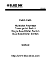
SEPTEMBER 2004
LHB4540A
LHB4541A
LHB4545A
LHB4546A
LHB4550A
LHB4551A
LHB4555A
LHB4556A
User Manual for
Plug & Play Fibre-to-the-Office Switch
(LHB454xA)
&
Intelligent Fibre-to-the-Office Switch
(LHB455xA)
Black Box Network Services
User Manual for the FTTO Switch including Management Option
Table of Contents
Introduction ..................................................................................................... 3
Characteristics ................................................................................................ 3
System Elements / Mounting Accessories...................................................... 4
Examples for mounting ................................................................................... 5
Installation....................................................................................................... 6
Switch Management (Intelligent versions only)............................................... 9
Device Manager.................................................................................... 9
Data prioritisation................................................................................ 10
VLANs................................................................................................. 11
Dimensions ................................................................................................... 12
Application .................................................................................................... 13
Order Information.......................................................................................... 14
Technical Specifications ............................................................................... 15
Black Box Contact Information ..................................................................... 16
Black Box Network Services
Page 2/16
User Manual for the FTTO Switch including Management Option
Page 3/16
Introduction
This FTTO-switch is the ideal switch to integrate into Fibre-to-the-Office applications. In this type of installations, fibre
cabling is installed starting from the patch panel and running through the cable ducts or sub floor systems. The fibre is then
terminated and connected to the Installation Switch, hence creating an active outlet of (4) 10/100 Switched Ethernet Copper
ports.
Apart from a Plug and Play version of the switch, there is also an "intelligent" version offering a variety of management &
configuration features.
All switches feature (4) STP ports and (1) Fibre port. The switches are physically different in terms of Fibre connector type
(SC or ST), and Fibre Mode (Multimode or Single Mode).
Special versions of the FTTO-switch exist, but are not explained in full detail. E.g. FTTO-switches for vertical mounting into
cable race ways or in prefab walls. Please contact our Tech Support to discuss your application.
Characteristics
All versions
l Fanless Fast Ethernet 10/100 Mbit/s installation switch.
l Extreme compact size and tool-less mounting with snap-in technology.
l Management via Device Manager and Web.
l 3,5 VA maximum power consumption.
l Five ports: 1x Optical Fiber uplink 100 Mbit/s; 4x RJ-45 10/100 Mbit/s.
l Twisted pair ports with full autonegotiation for 10/100 Mbit/s, half- or full-duplex operation.
l Layer 2 non-blocking switch, store-and-forward, 1024 MAC addresses, 1 Mbit RAM, HDX/FDX.
l Remotely configurable half- or full-duplex 100Base-FX-Port.
l Auto crossing functionality for all twisted pair ports.
Intelligent versions only (LHB455xA)
l Per port configuration via PC-based management-tool: 10/100 Mbit/s, half- or full-duplex operation
and autonegotiation (on/off).
l Management via an Integrated SNMP agent or TELNET-Interface is possible with the optional Extended Firmware
Package (LHB8200-FW11).
l Data prioritisation (Class of Service), port-based prioritisation (configurable via management-tool) and
packet-based prioritisation according to IEEE802.1q (VLAN-Tag), IPTOS-Field (DiffServ).
Black Box Network Services
User Manual for the FTTO Switch including Management Option
Page 4/16
System Elements
The installation switch is shown in fig. 1. The switch - including its installation socket - is mounted in the cable channel
(please refer to the paragraph “Installation” as well).
LED Indicators
Integrated Optical
Fiber Uplink
100Base-FX
RJ-45 Socket and
10/100Base-TX
Power Supply
(pluggable terminal block)
DIN Rail Bracket
(LHB4500-DIN)
Fig. 1: Installation Switch Elements
Mounting Accessories
The Installation-Switch supports with its tool-less snap-in mounting all cable-channel designs which conform to an
international standard. Two principal chassis options are available:
1.
2.
Standard Horizontal chassis (LHB45xxA): for installation in horizontal cable channels or wall mounting
Special Vertical chassis (Call tech Support): for installation in vertical locations as distribution columns or
sub floor mounting
The following mounting accessories are available:
a) Accessories for installation in standard Cable Raceways and DIN installation boxes
LHB4511, 2-part set
Cover frame
b)
Adapter plate
Accessories for installation in Ackermann-sub floor-tanks with 2-fold boxes
LHB4521, 3-part set:
Box
Frame
Blind cover
Black Box Network Services
User Manual for the FTTO Switch including Management Option
c)
Accessories for installation in Ackermann-sub floor-tanks with 3-fold boxes
LHB4522, 4-part set:
Box
d)
Page 5/16
Frame
Blind cover
Accessories for wall mounting
LHB4501, 2-part Set white:
Box
Frame
Examples for Mounting
Legrand Box
Adapter plate
Cover frame
FTTO-Switch
Fig. 2: horizontal mounting in cable
trunk (LHB4551A + LHB4511)
Fig. 3: vertical mounting in sub
floor box floor box (LHB4521)
Fig. 4: vertical mounting in
cable trunk (LHB4511)
Black Box Network Services
Fig. 5: wall mounting
(LHB4551A + LHB4501)
User Manual for the FTTO Switch including Management Option
Page 6/16
Installation
Fig. 6: Power connection
Safety Notes
L1
N
PE
DANGER!
Optical components can emit invisible laser radiation.
ATTENTION: Infrared light as it is used for data transmission on
optical fibers is not visible to the human eye, but nevertheless may
cause severe damage.
In order to prevent any eye damage:
Fig. 7: Installation in cover plate
• Never look into the output of optical fibers or components - risk of
severe eye damage!
• Apply protective caps to all unused optical ports.
• Do not start system operation prior to completing all wiring.
Active laser components employed in this system comply with laser
safety class 1.
Preparation of the Installation
Duplex FO cable has to be installed until the location of installation
FO connectors (according to the switch version) have to be
assembled.
Fig. 8: Snap in of blind plate
Preparation of the Power Connection
Outer coating of the power cable has to be removed appr. 45 mm
from the ends. Wires must be stripped and for strand wires end
sleeves have to be used.
Sub floor Mounting (Floor Tank)
To put holes at the relevant locations of the device holder (e. g. GB
E3 from Ackermann) for the injection of the wires. To bring the
FTTO Switch into the cover plate (GB3 from Ackermann) and snap
it in. (see fig. 7). Snap in the blind place cover (LP45 from
Ackermann) into the cover plate (GB3 from Ackermann) (see fig. 8).
Cord fastener hook to be snapped in into the relevant holes of the
cover plate and to thread the connections (power cable, FO cable).
Press the cord fastener hook together.
Fig. 9: Adapter plate in an E2 box
Cable Channel Mounting
The installation of the FTTO Switch into a cable channel results
under the use of the E2 Installation Box. This Installation Box is
specific and does not belong to the delivery of the switch.
Most of the used Installation systems do not support the 45x45
design. In order to be compatible to the most used systems special
designed adapters are available.
The 45x45 adapter has to be mounted on top of the standard
screwing of the E2 device holder (see fig. 9). The installation resp.
deinstallation of the switch has to be realized as described above by
snapping in into the considered locking of the 45x45 system (see
fig. 10). Finally the switch has to be fixed with the correct coloured
plastic cover (see fig. 11)
The adapter plate and the relevant plastic cover do not belong to the
standard delivery of the FTTO switch. It can be ordered under the
the art. No. LHB 4511.
For further information please contact the relevant support location.
Fig. 10: Snap in of the FTTO switch
Fig. 11: Fixing under use of the cover frame
Connections
Put in the FO connectors into the sockets of the FO connection of the
switch and lock it. It is very important, that the connection is done
according to the relevant marking on the FO cables. The FO cable
which comes from the transmitter must be connected with the
receiver and vice versa (crossing)
For the power connection special clamb connectors have to be used
and to be connected with the socket of the switch.
Black Box Network Services
User Manual for the FTTO Switch including Management Option
Page 7/16
Putting into Operation
Putting into operation can be realized without the (optional) Networkmanagement.
The switch is ready for operation with the factory adjustments.
For the configuration of the managed version the use of the Networkmanagement (Device Manager) is necessary. The
configuration of the unmanaged switches is possible by using the DIP switch on the bottom of the unit
Networkmanagement (optional)
The switch can be ordered with the integrated Networkmanagement as an option.
Putting into operation and configuration of the agent is possible with the help of powerfull Software Tool, which is not
delivered with the switch. The Manual of this “Device Manager” please find on the enclosed CD ROM
DIP-switches (optional)
The unmanaged version of the installation switch offers a manual
configuration via DIP-switches (see fig. 12). The functions are as
follow:
on
off
S1
1
Port4
10
2
Port3
10
3
Port2
10
4
Port1
10
S2
1
Port4
HDX
2
Port3
HDX
3
Port2
HDX
4
Port1
HDX
5
Uplink
HDX
6
Auto
neg
1-4
on
7
-
8
-
Port4
100
Port3
100
Port2
100
Port1
100
Port4
FDX
Port3
FDX
Port2
FDX
Port1
FDX
Uplink
FDX
Auto
neg
1-4
off
-
-
RESET push-button
The installation switch has two push-buttons to reset the switch. They
are located inside of the first two RJ-45 ports (see fig. 13). The buttons
are having the following functions:
Fig. 12: Configuration switches (unmanaged version):
Reset Switch: The button in RJ-45 port no. 2 is to set back the switch.
A short push of the button and the memory is cleared and all
connections are initialized. The configuration of the device (switch and
management) are unaffected by this reset.
IP Request (in combination with the management): For the first
assignment of the IP-address to the agent of the network management
(NMS) this IP request is necessary. To start this request the button in
port no. 2 has to be pushed for a longer time (approx. 5 s). To utilize
this request the Device manager software must be started and the
computer must be in the same physical and logical segment as the
switch. Additional information about this is on the CD-ROM of the
Device Manager Software.
Reset Switch-Configuration: With simultaneous pushing of the two
reset buttons, the configuration of the switch is set back to factory
default. This feature offers the possibility to get access to the
management in case of wrong configuration of e.g. the VLAN settings.
The configuration of the management agent is unchanged (e.g. IPaddress).
Configuration
switches
Switch
bottom side
on
off
1 2 3 4
1 2 3 4 5 6 7 8
S1
S2
Fig. 13: Reset Push-Button:
Important: All three functions are resetting the switch, that means the
memory is cleared and all connections are initialized.
Connections
Reset Push Button under the RJ-45 socket
The twisted pair ports do not need any differentiation between crossover
patch cables and 1:1 patch cables. The Auto Crossover feature allows
the installation switch to identify the connection type and to adjust the
interface automatically. In this way cascaded units as well as terminating
units can be connected effortless.
Using the switch management the Auto Crossover feature can be
disabled with individual ports being adjustable to either 1:1 or crossover
operation.
Black Box Network Services
User Manual for the FTTO Switch including Management Option
Page 8/16
The configuration of the fiber port is done manual, an automatic
configuration is not possible. As factory default the full duplex mode is
activated.
Attention: Distances of more than 412 m can be realized only in full
duplex mode. Please remind, that the opposite side of the switch must
support full duplex too, otherwise a faultless operation cannot be
guaranteed. A sign that full duplex is not supported is the increased
appearance of collisions during data transmission.
Now the switch is ready for operation.
LED displays
There are several LEDs for diagnostics available (see fig. 14). The
functions of these LEDs are described in fig. 15.
The LED FD indicated the full duplex operation mode of the related
port (constant on). In half duplex mode a blinking LED indicates
collisions on the related port.
Fig. 14: LED-Displays:
Fig. 15: Functions of the LED-displays:
ON Power, ready for operation
FD Fiber port configured for full duplex mode (on);
collision in half duplex mode (flashing) – according to
the configuration
L5 Fiber connection correct (on); Data transmission
on fiber port (flashing)
L1-L4 Twisted Pair connections correct (on);
Data received on this port (flashing)
L0 Without function
Black Box Network Services
User Manual for the FTTO Switch including Management Option
Page 9/16
Switch Management (Intelligent versions only)
Device Manager
The PC-based management tool allows for the manual configuration of the individual installation switch interfaces (please
refer to figure 17: Black Box Device Manager).
The initial TCP-IP parameters (IP-address, gateway etc.) are set via the same tool. Later on these parameters can be modified
by means of the TCP/IP protocol.
All management information is provided within the network (Inband Management). With no special interface being required
for this all four twisted pair ports are available to the user.
Fig. 16: Black Box Device Manager
With the Autonegotiation function being deactivated the twisted pair interfaces need to be configured manually. Relevant
parameters are transmission speed (10/100 Mbit/s) and way of operation (Half or Full Duplex). Using the same management
screen dedicated TP-ports can be activated or deactivated.
Fig. 17: Interface Configuration
Black Box Network Services
User Manual for the FTTO Switch including Management Option
Page 10/16
Switch Management (Intelligent versions only)
Data Prioritisation
In order to allow for a prioritisation of the various data streams individual data packets are marked with a tag. This tag is
recognized by each network element within the data path and therefore transmitted with a defined priority. Three different
prioritisation methods are supported by the 45x45 installation switch:
• Based on layer 1:
This option is available through the integrated management port configuration tool (IntServ). The user can activate a
generic prioritisation of one port over the other ports of the installation switch. The configuration is carried out via the
menu “Standard Settings” (please refer to figure 18).
• Based on layer 2:
Layer 2 based prioritisation is possible by setting a 3 bit VLAN tag according to IEEE 802.1p, which equates to eight
prioritisation levels. Using the IEEE 802.1q configuration (please refer to figure 19) each level can be allocated to the Hi
or Low queue.
• Based on layer 3:
The third method of prioritisation is based on layer 3 Differentiated Service (DiffServ) feature. 6 bits of the Type of
Service (ToS) field of the IP header - equivalent to 64 different classes of prioritisation - are utilised for this method. The
allocation of the various classes of prioritisation to the Hi or Low queue is carried out via the DiffServ settings.
Fig. 18: Layer 2 / Layer 3 Prioritisation
Two data queues are used for the data prioritisation process. Based on the configuration setting the switch will allocate the
data to either of the two queues. In addition to this the user can set the service ratio between these queues (please refer to
figure 18).
Black Box Network Services
User Manual for the FTTO Switch including Management Option
Page 11/16
Switch Management (Intelligent versions only)
VLANs
By creating VLANs the user can segment local area networks independent of the physical topology.
The individual data packets and their allocation to a specific VLAN need to be identified. For doing so a 4 byte VLAN-tag
containing a Virtual ID (VID) according to IEEE 802.3q has been defined. The VLAN-tag is attached to each data packet.
The installation switch analyses the VID. In case non-VLAN-tag capable data equipment is connected to the installation
switch, the said VLAN-tag can be created. For doing so two different methods might be applied:
• Tagging:
A VLAN-tag with configurable content (VID and layer 2 prioritisation) is attached to each data packet. If incoming data
exhibit an already attached VLAN-tag the installation switch analyses this particular VLAN-tag, but will not overwrite it.
• Trunking:
In this case data packets are filtered and not manipulated (no change of the VID), even if the VLAN-tag is absent. The
data filtering is taking place on the basis of the allocated and approved VLANs. The installation switch can handle up to
16 out of the 4096 possible VLANs.
Abb. 19: VLAN-Settings
An individual VLAN might be allocated to the internal installation switch management port, thus adding further security to
the system and allowing only the administrator of this particular VLAN to configure the installation switch. However, there is
a risk to be taken into account: the access to the installation switch management agent is blocked if the VLAN configuration
is set incorrectly, therefore - by activating the Reset push button - enforcing a complete installation switch configuration
reset.
Black Box Network Services
User Manual for the FTTO Switch including Management Option
Dimensions
Installation Depth:
• maximum 33 mm for the cable channel
Black Box Network Services
Page 12/16
User Manual for the FTTO Switch including Management Option
Application
Fig. 20: Typical FTTO-Application
Black Box Network Services
Page 13/16
User Manual for the FTTO Switch including Management Option
Order Information
Plug & Play FTTO Switch
Art.-No.
LHB4540A
Description
Ethernet Installations-Switch 45x45
1300nm Multimode ST, horizontal
Connectors
4x RJ45
2x ST
10/100Base-TX
100Base-FX
LHB4541A
Ethernet Installations-Switch 45x45
1300m Multimode SC, horizontal
4x RJ45
2x SC
10/100Base-TX
100Base-FX
LHB4545A
Ethernet Installations-Switch 45x45
1300m Single mode ST, horizontal
4x RJ45
2x ST
10/100Base-TX
100Base-FX
LHB4546A
Ethernet Installations-Switch 45x45
1300m Single mode SC, horizontal
4x RJ45
2x SC
10/100Base-TX
100Base-FX
Intelligent FTTO Switch
Art.-No.
LHB4550A
Description
Ethernet Installations-Switch 45x45
1300nm Multimode ST, horizontal
Connectors
4x RJ45
2x ST
10/100Base-TX
100Base-FX
LHB4551A
Ethernet Installations-Switch 45x45
1300m Multimode SC, horizontal
4x RJ45
2x SC
10/100Base-TX
100Base-FX
LHB4555A
Ethernet Installations-Switch 45x45
1300m Single mode ST, horizontal
4x RJ45
2x ST
10/100Base-TX
100Base-FX
LHB4556A
Ethernet Installations-Switch 45x45
1300m Single mode SC, horizontal
4x RJ45
2x SC
10/100Base-TX
100Base-FX
LHB8200-FW11
Extended Firmware Package
(SNMP & Telnet support) for
Intelligent FTTO Switch only
Accessories
Art.-No.
LHB4501
LHB4511
LHB4521
LHB4522
LHB4500-DIN
Description
Installation box for wall mounting, white
Mounting kit for cable raceway DIN installation boxes
Mounting kit for Ackermann GB2 (sub-floor box)
Mounting kit for Ackermann GB3 (sub-floor box)
DIN-rail mounting bracket for FTTO-switch
Black Box Network Services
Page 14/16
User Manual for the FTTO Switch including Management Option
Page 15/16
Technical Specifications
Type
Fast Ethernet Installations Switch 45x45
4 Port 10/100Base-TX + 1 Port 100Base-FX
According to IEEE 802.3u for installation in cable channels
and sub floor boxes
Cable Type
Twisted Pair Cable, Category 5 or higher
with RJ45 Plug
Optical Fibre Type
Multimode models accept 50 or 62,5/125 µm fibre, duplex
Single Mode models accept 9/125 µm fibre, duplex
Fibre Connectors
Duplex ST- or SC-Connectors
Data Transmission Rate
TP: 10/100 Mbps (Autonegotiation)
FX: 100 Mbps (configurable Full Duplex Operation)
Fibre Optic Wavelength
1300 nm (Multimode/Single mode)
Optical Output Power
-19 dBm (1300 nm Multimode)
-15 dBm (1300 nm Single mode)
Receiver Sensitivity
-30 dBm (1300 nm Multimode)
-31 dBm (1300 nm Single mode)
Max. Transmission
Distance
LED Indicators
Multimode, Full Duplex: 2-km
Single mode, Full Duplex: 15-km
Single mode, Full Duplex (special Long-Haul version): 40-km
ON
Power, ready for operation
FD
Fiber port configured for full duplex mode (on);
collision in half duplex mode (flashing) – according to the configuration
L5
Fiber connection correct (on); Data transmission on fiber port (flashing)
L1-L4 Twisted Pair connections correct (on); Data received on this port (flashing)
L0
Without function
Power
230VAC / 3.5VA Internal Power Supply
Operating Temperature
0°C to 50°C
Storage Temperature
-20°C to 85°C
Relative Humidity
5% to 80%, non condensing
Management
(Intelligent versions only)
- Status Information via Web-based Management http-Server
- Configuration via PC-based Management Tool
- Configuration via Telnet with Extended Firmware Package (LHB8200-FW11)
- Monitoring/Configuration via SNMPv1
with Extended Firmware Package (LHB8200-FW11)
Black Box reserves the right to make any changes without further notice to any product to improve reliability, function or design. Black Box does not assume any
liability arising out of the application or use of any product. 09/04
Black Box Network Services
User Manual for the FTTO Switch including Management Option
Page 16/16
Black Box Contact Information
Country
Web
E-mail Sales
E-mail Tech
Telephone
Austria
Belgium
Denmark
Finland
France
Germany
Italy
Norway
Spain
Sweden
Switzerland
The Netherlands
United Kingdom
www.black-box.at
www.blackbox.be
www.blackbox.dk
www.blackbox.fi
www.blackbox.fr
www.black-box.de
www.blackbox.it
www.blackboxnorge.no
www.blackbox.es
www.blackboxab.se
www.black-box.ch
www.blackbox.nl
www.blackbox.co.uk
[email protected]
[email protected]
[email protected]
[email protected]
[email protected]
[email protected]
[email protected]
[email protected]
[email protected]
[email protected]
[email protected]
[email protected]
[email protected]
[email protected]
[email protected]
[email protected]
[email protected]
[email protected]
[email protected]
[email protected]
[email protected]
[email protected]
[email protected]
[email protected]
[email protected]
[email protected]
+43 (0)1 256 98 56
+32 (0)2 725 85 50
+45 56 63 30 10
+358 (0)201 888 888
+33 (0)1 45 60 67 00
+49 (0)811 5541-210
+39 (0)2-27.404.311
+47 55 300 700
+34 916590191
+46 8 44 55 870
+41 (0)55 451 70 70
+31 (0)30-2417788
+44 (0)118 965 5100
Black Box Network Services