1
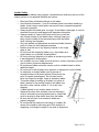
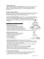
EVANSTON UTILITIES DEPARTMENT
Study / Training Guide for
Water Production Water Worker I
General Description of Water Treatment Plant
The water from Lake Michigan, which is the source of water for the Evanston
Treatment Facility, must first be treated for use as a potable drinking water
supply. The steps in this treatment process are as follows and please refer to the
drawing titled Figure 1 at the end of this section as well:
1. INTAKE SYSTEM
Water is drawn from Lake Michigan through three large intake pipes at a depth of
approximately 28 feet. Chlorine is also fed into the head of the intakes for the
control of zebra and quagga mussels, small mollusks that can plug intake
structures.
2. SUCTION WELLS
Lake water flows by gravity through the intake pipes into three suction wells.
Activated carbon is added when needed in the suction wells for longer contact
with the water to remove taste and odor.
3. LOW LIFT PUMPS
Six electric centrifugal pumps are provided to lift the water from the lake to a level
that it can flow by gravity through the treatment plant at a total pumping capacity
of 135 million gallons per day. Four of the units have auxiliary natural gas engine
drives for emergency operation in case of a power failure, providing 75 million
gallons per day (MGD) of emergency capacity.
4. FLASH MIX BASIN
This is a concrete tank with a vertical mixing paddle and is the point where
treatment begins as liquid aluminum sulfate, polymer, chlorine and fluoride are
added to the raw water and mixed. The chlorine is for disinfection and oxidation
of organic materials. The aluminum sulfate and polymer are added to form a
precipitate or floc in the water which causes the suspended solids to settle out as
sludge. Fluoride is added to help reduce the incidence of dental decay.
5. CHEMICAL FEEDERS
The chemical feeders supply accurately measured amounts of liquid chemicals
based on raw water quality and pumpage rates to be sure the proper amounts of
chemicals are fed into the water.
6. SLOW MIX BASIN
The water next flows to the slow mix basins which are large chambers containing
slow moving horizontal paddles. It is here that the chemicals are mixed and the
floc increases in size before entering the settling basins.
Page 1 of 19
7. SETTLING BASINS
Upon leaving the slow mix basins, the water enters the four large settling basins
which have a total capacity of 14,330,000 gallons. It takes from 4 to 8 hours for
the water to flow through the settling basins. In this process over 90% of all
suspended impurities are removed.
8. BASIN SLUDGE DRAIN
The sludge is cleaned from the settling basins twice per year and is pumped
through an 8" force main into a large interceptor sewer to be treated by the
Metropolitan Water Reclamation District of Greater Chicago at their local
facilities.
9. FILTERS
The water next flows to the rapid sand filters where the last traces of turbidity and
bacteria are removed. There are 24 filters operating in parallel for a total rated
capacity of 108 million gallons per day. The filters are constructed in shallow
concrete tanks with an under-drain system at the bottom, followed by filter sand
and then topped off with anthracite coal. When clogged, the filters are
backwashed by reversing the flow for about 8 minutes.
10. DETENTION BASIN
The detention basin was designed to collect all of the filter wash water and stop it
from going back into Lake Michigan. The wash water is recycled back into the
incoming raw water at approximately 10% of total raw water intake. A 700 gpm
pump discharges the sludge to the basin sludge drain described in Step 8.
11. CLEAR WELLS AND UNDERGROUND STORAGE
Clear well reservoirs beneath the filters and an underground storage tank provide
9,500,000 gallons of reserve storage from which the distribution system is
supplied. Before entering the reservoirs, a final post chemical treatment of
chlorine is added when needed along with a blended phosphate corrosion control
compound.
12. HIGH LIFT PUMPS
Eight centrifugal pumps, with a total capacity of 147 MGD, supply water pressure
at 50 to 65 pounds per square inch to the distribution system. Five of the units
are equipped with auxiliary natural gas engine drives for emergency operation in
the event of a power failure, providing 87 MGD emergency capacity.
13. ELEVATED STORAGE AND REMOTE BOOSTER STATIONS
The Evanston distribution system contains two standpipes with remote booster
pumps. The southwest standpipe can store up to 5.0 million gallons and the
northwest standpipe up to 7.5 million gallons. A 5.0 million gallon standpipe and
a 5.0 million gallon surface reservoir, both with remote booster pumps, are
located in Skokie. The standpipes float on the system and tend to level out peak
loads, pressure fluctuations, and provide a reservoir for emergencies.
Page 2 of 19
SAFETY
The work performed by the Water Production Water Worker I requires some
knowledge of working safely. The following information is a broad outline of
these procedures.
Confined Space
A confined space has limited openings for entry or exit, is large enough for
entering and working, and is not designed for continuous worker occupancy.
Confined spaces include underground vaults, tanks, storage bins, manholes, pits,
underground utility vaults and pipelines. See 29 CFR 1910.146.
Confined spaces are categorized as non-permit required or permit required.
Non-Permit-required confined spaces are confined spaces that have none
hazards listed below in the Permit required confined spaces.
Permit-required confined spaces are confined spaces that:
May contain a hazardous or potentially hazardous atmosphere.
May contain a material which can engulf an entrant.
May contain walls that converge inward or floors that slope downward and
taper into a smaller area which could trap or asphyxiate an entrant.
May contain other serious physical hazards such as unguarded machines
or exposed live wires.
Must be identified by the employer who must inform exposed employees
of the existence and location of such spaces and their hazards.
What to Do
Do not enter permit-required confined spaces without being trained and
without having a permit to enter.
Review, understand and follow City of Evanston procedures before
entering permit-required confined spaces. Know how and when to exit.
Before entry, identify any physical hazards.
Before and during entry, test and monitor for oxygen content, flammability,
toxicity or explosive hazards as necessary.
Use fall protection, rescue, air-monitoring, ventilation, lighting and
communication equipment according to entry procedures.
Maintain contact at all times with a trained attendant either visually, via
phone, or by two-way radio. This monitoring system enables the attendant
and entry supervisor to order you to evacuate and to alert appropriately
trained rescue personnel to rescue entrants when needed.
Page 3 of 19
Ladder Safety
Falls from portable ladders (step, straight, combination and extension) are one of the
leading causes of occupational fatalities and injuries.
Read and follow all labels/markings on the ladder.
Avoid electrical hazards! – Look for overhead power lines before handling a
ladder. Avoid using a metal ladder near power lines or exposed energized
electrical equipment.
Always inspect the ladder prior to using it. If the ladder is damaged, it must be
removed from service and tagged until repaired or discarded.
Always maintain a 3-point (two hands and a foot, or two feet
and a hand) contact on the ladder when climbing. Keep your
body near the middle of the step and always face the ladder
while climbing (see diagram).
Only use ladders and appropriate accessories (ladder levelers,
jacks or hooks) for their designed purposes.
Ladders must be free of any slippery material on the rungs,
steps or feet.
Do not use a self-supporting ladder (e.g., step ladder) as a
single ladder or in a partially closed position.
Do not use the top step/rung of a ladder as a step/rung unless
it was designed for that purpose.
Use a ladder only on a stable and level surface, unless it has been secured
(top or bottom) to prevent displacement.
Do not place a ladder on boxes, barrels or other unstable bases to obtain
additional height.
Do not move or shift a ladder while a person or equipment is on the ladder.
An extension or straight ladder used to access an
elevated surface must extend at least 3 feet above the
point of support (see diagram). Do not stand on the
three top rungs of a straight, single or extension ladder.
The proper angle for setting up a ladder is to place its
base a quarter of the working length of the ladder from
the wall or other vertical surface, a 1 to 4 ratio (see
diagram).
A ladder placed in any location where it can be
displaced by other work activities (such as doorways)
must be secured to prevent displacement or a barricade
must be erected to keep traffic away from the ladder.
Be sure that all locks on an extension ladder are
properly engaged.
Do not exceed the maximum load rating of a ladder. Be
aware of the ladder’s load rating and of the weight it is
supporting, including the weight of any tools or equipment.
Page 4 of 19
Fall Protection
Fall Protection in General Industry
Falls are among the most common causes of serious work-related injuries and
deaths. Employers must take measures in their workplaces to prevent employees
from falling off overhead platforms, elevated work stations or into holes in the
floor and walls.
To prevent employees from being injured from falls, employers must:
Guard every floor hole into which a worker can accidentally walk by use of
a railing and toe board or a floor hole cover.
Provide a guardrail and toe board around every open-sided platform, floor
or runway that is 4 feet or higher off the ground or next level.
Regardless of height, if a worker can fall into or onto dangerous machines
or equipment (such as a vat of acid or a conveyor belt), employers must
provide guardrails and toe boards to prevent workers from falling and
getting injured.
Other means of fall protection that may be required on certain jobs include
safety harness and line, safety nets, stair railings and handrails.
OSHA requires employers to:
Provide working conditions that are free of known dangers.
Keep floors in work areas in a clean and sanitary condition.
Select and provide required personal protective equipment at no cost to
workers.
Train workers about job hazards in a language that they can understand.
Page 5 of 19
Respirators
Protect Yourself
Respiratory protection must be worn whenever you are working in a hazardous
atmosphere. The appropriate respirator will depend on the contaminant(s) to
which you are exposed and the protection factor (PF) required. Required
respirators must be NIOSH-approved and medical evaluation and training must
be provided before use.
Single-strap dust masks are usually not NIOSH-approved. They must not be
used to protect from hazardous atmospheres. However, they may be useful in
providing comfort from pollen or other allergens.
Approved filtering face-pieces (dust masks) can be used for dust, mists,
welding fumes, etc. They do not provide protection from gases or vapors. DO
NOT USE FOR ASBESTOS OR LEAD; instead, select from the respirators
below.
Half-face respirators can be used for protection against most vapors, acid
gases, dust or welding fumes. Cartridges/filters must match contaminant(s) and
be changed periodically.
Full-face respirators are more protective than half-face respirators. They can
also be used for protection against most vapors, acid gases, dust or welding
fumes. The face-shield protects face and eyes from irritants and contaminants.
Cartridges/filters must match contaminant(s) and be changed periodically.
Loose-fitting powered-air-purifying respirators (PAPR) offer breathing
comfort from a battery- powered fan which pulls air through filters and circulates
air throughout helmet/hood. They can be worn by most workers who have
beards. Cartridges/filters must match contaminant(s) and be changed
periodically.
A Self-Contained Breathing Apparatus (SCBA) is used for entry and escape
from atmospheres that are considered immediately dangerous to life and health
(IDLH) or oxygen deficient. It has its own air tank.
Page 6 of 19
Electrical Safety
Electrical hazards can cause burns, shocks and electrocution (death).
• Assume that all overhead wires are energized at lethal voltages. Never assume
that a wire is safe to touch even if it is down or appears to be insulated.
• Stay at least 10 feet (3 meters) away from overhead wires during cleanup and
other activities. If working at heights or handling long objects, survey the area
before starting work for the presence of overhead wires.
• Never operate electrical equipment while you are standing in water.
• Never repair electrical cords or equipment unless qualified and authorized.
• Have qualified personnel inspect electrical equipment that has gotten wet
before energizing it.
• If working in damp locations, inspect electric cords and equipment to ensure
that they are in good condition and free of defects, and use a ground-fault circuit
interrupter (GFCI).
• Always use caution when working near electricity.
• Extension Cords
Normal wear on cords can loosen or expose wires. Cords that are not 3-wire
type, not designed for hard-usage, or that have been modified, increase your risk
of contacting electrical current.
• Use only equipment that is approved to meet OSHA standards.
• Do not modify cords or use them incorrectly.
• Use factory-assembled cord sets and only extension cords that are 3-wire type.
• Use only cords, connection devices, and fittings that are equipped with strain
relief.
• Remove cords from receptacles by pulling on the plugs, not the cords
Page 7 of 19
Personal Protective Equipment (PPE)
Eye and Face Protection
• Safety glasses or face shields are worn any time work operations can cause
foreign objects to get in the eye. Eye and or face protection is required during
welding, cutting, grinding, nailing or when working with concrete, chemicals or
exposed to flying particles. The type of eye and or face protection should be
selected based on anticipated hazards.
Foot Protection
• Work boots or shoes with slip-resistant, puncture-resistant, rubber insulated
soles.
• Safety-toed footwear is worn to prevent crushed toes when working around
heavy equipment or falling objects. Safety toed shoes are required by the City
and are to be worn at all times.
Hand Protection
• Gloves should fit snugly, but not feel restrictive.
• The right gloves for the job should be worn by workers (examples: leather
palm work gloves for general protection, rubber gloves for solvents, oils or
chemical or concrete work; welding gloves for welding; insulated gloves for cold
weather work).
Head Protection
• Wear hard hats where there is a potential for objects falling from above, bumps
to the head from fixed objects, or of accidental head contact with electrical
hazards.
• Hard hats – routinely inspect them for dents, cracks or deterioration; replace
after a heavy blow or electrical shock; maintain in good condition. Replace after
reaching the expiration date.
Hearing Protection
• Use earplugs/earmuffs in high noise work areas, and clean or replace them
regularly. Hearing protection is required at levels greater than 85 decibels.
Rules of Thumb. Hearing protection may be needed if:
• You have to raise your voice significantly to be heard by someone three feet
away.
• After leaving a noisy area, your ears feel plugged or you hear a mild ringing or
whooshing noise that goes away after an hour or two.
Eye Protection against Radiant Energy during Welding and Cutting
• Electromagnetic energy given off by an arc or flame can injure workers’ eyes
and is commonly referred to as radiant energy or light radiation. For protection
workers must use safety glasses, goggles, welding helmets, or welding face
shields. This equipment has filter lenses with a numbered shade that provides
appropriate protection. The higher the lens shade number the darker the filter
and the less light radiation that will pass through the lens. This requirement
applies to the employees performing the work and to personnel observing
Page 8 of 19
the operation. The tables posted in the shop welding area list the minimum
protective lens shade numbers for commonly used welding and cutting
processes. If you are not sure, ask the supervisor.
Lockout – Tagout
“Lockout/tagout” refers to specific practices and procedures to safeguard
employees from the unexpected energization or startup of machinery and
equipment, or the release of hazardous energy during service or maintenance
activities.
Lockout devices hold energy-isolation devices in a safe or “off” position. They
provide protection by preventing machines or equipment from becoming
energized because they are positive restraints that no one can remove without a
key, or through extraordinary means, such as bolt cutters.
Tagout devices, by contrast, are prominent warning devices that an authorized
employee fastens to energy-isolating devices to warn employees not to
reenergize the machine while he or she services or maintains it. Tagout devices
are easier to remove and, by themselves, provide employees with less protection
than do lockout devices.
Before beginning service or maintenance, the following steps must be
accomplished in sequence and according to the city’s energy-control procedure:
(1) Prepare for shutdown;
(2) Shut down the machine;
(3) Disconnect or isolate the machine from the energy source(s);
(4) Apply the lockout or tagout device(s) to the energy-isolating device(s);
(5) Release, restrain, or otherwise render safe all potential hazardous stored or
residual energy. If a possibility exists for re-accumulation of hazardous energy,
regularly verify that such energy has not re-accumulated; and
(6) Verify the isolation and de-energization of the machine.
Before removing lockout or tagout devices, the employee(s) must take the
following steps in accordance with the energy-control procedure:
• Inspect machines or their components to assure that they are operationally
intact and that nonessential items are removed from the area; and
• Check to assure that everyone is positioned safely and away from machines.
After removing the lockout or tagout devices but before reenergizing the
machine, make sure that all employees who operate or work with the machine,
as well as those in the area know that the devices have been removed and that
the machine is capable of being reenergized.
Employees who work on de-energized machinery may be seriously injured or
killed if someone removes lockout/tagout devices and reenergizes machinery
without their knowledge. Thus, it is extremely important that all employees
respect lockout and tagout devices and that only the person(s) who applied these
devices remove them.
Page 9 of 19
In the rare situation in which the employee who placed the lockout/tagout device
is unable to remove that device, another person may remove it under the
direction of the Division Chief.
HAZ COM - SDS
The Hazard Communication Standard (HCS) requires chemical manufacturers,
distributors, or importers to provide Safety Data Sheets (SDSs) (formerly known
as Material Safety Data Sheets or MSDSs) to communicate the hazards of
hazardous chemical products. As of June 1, 2015, the HCS will require new
SDSs to be in a uniform format, and include the section numbers, the headings,
and associated information under the headings below:
Section 1, Identification includes product identifier; manufacturer or distributor
name, address, phone number; emergency phone number; recommended use;
restrictions on use.
Section 2, Hazard(s) identification includes all hazards regarding the chemical;
required label elements.
Section 3, Composition/information on ingredients
includes information on chemical ingredients; trade secret claims.
Section 4, First-aid measures includes important symptoms/effects, acute,
delayed; required treatment.
Section 5, Fire-fighting measures lists suitable extinguishing techniques,
equipment; chemical hazards from fire.
Section 6, Accidental release measures lists emergency procedures;
protective equipment; proper methods of containment and cleanup.
Section 7, Handling and storage lists precautions for safe handling and
storage, including incompatibilities.
Section 8, Exposure controls/personal protection lists OSHA’s Permissible
Exposure Limits (PELs); Threshold Limit Values (TLVs); appropriate engineering
controls; personal protective equipment (PPE).
Section 9, Physical and chemical properties lists the chemical’s
characteristics.
Section 10, Stability and reactivity lists chemical stability and possibility of
hazardous reactions.
Section 11, Toxicological information includes routes of exposure; related
symptoms, acute and chronic effects; numerical measures of toxicity.
Section 12, Ecological information*
Section 13, Disposal considerations*
Section 14, Transport information*
Section 15, Regulatory information*
Section 16, Other information, includes the date of preparation or last revision.
Page 10 of 19
Tool Safety
Hand tools are tools that are powered manually. Hand tools include anything
from axes to wrenches. The greatest hazards posed by hand tools result from
misuse and improper maintenance.
Some examples of misuse or improper maintenance include the following:
• If a screwdriver is used as a chisel, the tip of the screwdriver may break and fly
off, hitting the user or other employees.
• If a wooden handle on a tool, such as a hammer or an axe, is loose, splintered,
or cracked, the head of the tool may fly off and strike the user or other
employees.
• If the jaws of a wrench are worn, the wrench might slip.
• If impact tools such as chisels, wedges, or drift pins have mushroomed heads,
the heads might shatter on impact, sending sharp fragments flying toward the
user or other employees.
The Utilities Department does not permit the use of unsafe hand tools.
Employees are trained in the proper use and handling of tools and equipment.
When using saw blades, knives, or other tools, employees should direct the tools
away from aisle areas and away from other employees working in close
proximity. Knives and scissors must be sharp; dull tools can cause more hazards
than sharp ones.
Power tools must be fitted with guards and safety switches because they
are extremely hazardous when used improperly. The types of power tools are
determined by their power source: electric, pneumatic, liquid fuel, hydraulic, and
powder-actuated.
To prevent hazards associated with the use of power tools, workers should
observe the following general precautions:
• Never carry a tool by the cord or hose.
• Never yank the cord or the hose to disconnect it from the receptacle.
• Keep cords and hoses away from heat, oil, and sharp edges.
• Disconnect tools when not using them, before servicing and cleaning them, and
when changing accessories such as blades, bits, and cutters.
Page 11 of 19
• Keep all people not involved with the work at a safe distance from the work
area.
• Secure work with clamps or a vise, freeing both hands to operate the tool.
• Avoid accidental starting. Do not hold fingers on the switch button while carrying
a plugged-in tool.
• Maintain tools with care; keep them sharp and clean for best performance.
• Follow instructions in the user’s manual for lubricating and changing
accessories.
• Be sure to keep good footing and maintain good balance when operating power
tools.
• Wear proper apparel for the task. Loose clothing, ties, or jewelry can become
caught in moving parts.
• Remove all damaged portable electric tools from use and tag them: “Do Not
Use.”
Lawn Mowing and Trimming Equipment
Safety glasses, ear and foot protection must be worn at all times when operating
equipment.
To prevent accidents with mowers and trimmers, read and follow directions in the
equipment operator’s manual. Pay attention to safety instructions in the manual
and to warning labels you see on the equipment. If you have questions, stop and
ask your supervisor before you continue.
Pre-Start Inspection
Safety starts before the engine. A thorough visual inspection of the mower or
trimmer is important before beginning work each day. Alert your supervisor if you
find anything wrong during your daily pre-start inspection.
Missing or Damaged Guards
Guards and shields protect you from moving parts make sure they are in good
order.
Tires
Check tire pressure and look for signs of damage. Make sure lug bolts are tight.
Fluid Leaks
Fluid leaks can be a fire hazard as well as cause break-downs or slip hazard.
Belts
Check for loose or damaged belts. Tighten loose belts and replace belts if any
ply separation or cracks are visible.
Blade
Make sure the blade is secure, balanced and covered to prevent injury. Report
bent cracked or worn blades to your supervisor. Protect your hands with heavyduty gloves when inspecting blades.
Accumulated Grass or Grease
Check the mower deck and chute for accumulations of grass clippings, leaves,
grease and other debris.
Page 12 of 19
Prepare Mowing Area
Walk the area to be mowed. Pick up debris such as rocks, sticks, bottles, cans,
wires, etc. Debris picked up by a mower or trimmer can be thrown from the
machine at speeds as high as 200 m.p.h. or cause the equipment to jam or
malfunction.
Be Aware of Surroundings
Be aware at all times of the location of coworkers. Keep all others out of the area
while you are mowing or trimming. Make sure that the chute of the mower is
pointed away from people, animals, buildings and traffic.
Concentrate on Working Safely. Sometimes you may be tempted to take risky
shortcuts. Remember, an accident can leave you permanently injured or cut your
life short. For your safety and the safety of those around you, do not take
unnecessary risks. No deadline is so pressing you can’t take the time to do your
work safely.
Lawn Mowing and Trimming Equipment
Start Up Safety Procedures
1. Make sure all attachments are disengaged.
2. Shift into neutral before starting the engine.
• Start riding equipment from the operator’s seat only.
• Always start string/brush trimmers on the ground.
• Keep hands and feet away from the blade area when starting walk behind mowers.
Safe Shut Down Procedures
1. Disengage the blade and other attachments.
2. Lower the attachments to the ground.
3. Shift the controls into neutral.
4. Set the parking brake.
5. Turn off the engine.
6. Dismount the equipment.
Safe Refueling Procedures to help reduce the risk of fuel ignition.
• Always shut off engine, wait at least 5 minutes for engine to cool before refueling.
• Use approved fuel containers in a ventilated area, store away from direct sunlight.
• Never smoke or have an open flame near fuel
• Touch the fuel nozzle to the machine before removing the fuel cap to prevent a
static spark from igniting the fuel.
• Use a funnel or a non-spill nozzle when fueling to reduce spillage.
• Keep the nozzle or funnel in contact with the fuel tank while filling.
• Wipe up all spills immediately, before starting the engine.
• Never clean your hands with gasoline. Use a nonflammable solvent instead.
To Properly Fill Fuel Containers:
1. Set the container on the ground; do not fill containers in the bed of a pickup.
2. Touch the nozzle to the container before removing the container lid.
3. Keep the nozzle in contact with the container while filling.
Page 13 of 19
4. Don’t fill to the brim. Leave room for expansion. Portable containers and gas tanks
should be filled 3/4 full.
Additional Precautions
• Be cautious on wet grass. Slips on wet grass can cause you to fall into the
equipment’s moving parts. Also, wet grass can cause riding mowers to slide or skid.
• Do not stand in the road to trim grass or brush. Stand away from the road and
watch for traffic.
Avoid Heat Related Illnesses
• Drink water often throughout the day; don’t wait until you’re thirsty to get a drink.
• Stay away from soda, coffee, tea and drinks that dehydrate the body.
• Avoid large meals before working in the heat.
• Plan to do the heaviest work at the coolest part of the day.
• Some prescriptions can make you more susceptible to heat illnesses. Check with
your doctor to see if any medicine you are taking could affect you working in the
heat.
WATER DISTRIBUTION SYSTEM
The Evanston Water Distribution System is comprised of 157 miles of water
main, approximately 2,050 distribution valves, approximately 1,400 fire hydrants
and approximately 14,350 water services, two water storage facilities and the
pumping station at the treatment facility. The water mains convey treated water
that is pumped under pressure from the Evanston water treatment facility to the
approximate 14,350 retail customers in Evanston and the City’s two wholesale
water customers, the Village of Skokie and the Northwest Water Commission
(Arlington Heights, Buffalo Grove, Palatine, and Wheeling).
The main purposes of the distribution system are: 1)to deliver adequate
quantities of water at sufficient pressures at all times and 2) protect the quality of
the water by maintaining continuous positive water pressure in the distribution
system to assure that the potable water is not contaminated by ground water.
Generally, water should be delivered at a minimum pressure of 35 pounds per
square inch (psi), and 20 psi is the absolute lowest acceptable pressure needed
to assure that the potable water is not contaminated by ground water. Water
leaving the high lift pump station is typically at a pressure of 50-53 psi.
WATER MAINS
Water mains are pipelines that supply water from the water plant pumping station
to the water services that serve individual buildings. Water mains in Evanston
vary in size from 3-inch diameter to 48-inch diameter.
VALVES
Distribution valves are installed in the water main system in order to shut down
and isolate a section of water main for repair or maintenance. Distribution valves
are generally located at street intersections and are installed in valve vaults or
valve boxes. Valve vaults are generally 48-inch diameter structures, constructed
of brick, concrete block or concrete sections that are placed over the valve and
Page 14 of 19
allow access to the valve for maintenance purposes through a 22-inch diameter
frame and solid cover at the street level. Valve boxes are 6-inch diameter
sections of pipe set vertically over the valve operating nut to the street level.
Valve boxes allow operation of the valve using a valve key. Valves are
strategically placed to limit the number of water services that will be impacted
when a section of water main is isolated. Sections of water main are isolated to
allow for the repair of a leaking water main, the installation of a new fire hydrant
or new large-diameter water service. Valves are also used throughout the water
treatment plant both internally and near Lincoln Street.
Gate valves are generally used in the distribution system because when the
valve is fully open there is no obstruction in the flow path of the water. The gate
or wedge portion of the valve slides into the bonnet portion of the valve getting
completely out of the path of the fluid. As such, there is no loss of flow through a
gate valve. Gate valves placed on larger diameter water mains usually require
the valve to be placed on their side, meaning that the bonnet is next to rather
than above the water main. Gate valves placed on their side can become difficult
to operate over time because the bottom track that the gate slides on gets filled
with debris.
Evanston has also used butterfly valves in the distribution system on some of the
larger diameter water mains. This type of valve is less expensive, but even in the
open position, the disk of the valve is in the path of water causing resistance.
Butterfly valves operate very quickly from the open to close position.
FIRE HYDRANTS
The primary purpose of a fire hydrant is to provide water to the fire department in
the event of a fire. Fire hydrants should be placed so that no more than 200 feet
of fire hose is needed between the fire hydrant and the fire. As such, fire
hydrants are generally spaced every three hundred feet on a water main. Fire
hydrants are also used to flush or clean debris and sediment from the water
main.
WATER SERVICES
Water services are the pipes that convey the treated water under pressure from
the water main in the street to the building. Most single family residential homes
have water services that range in size from ¾” to 2“. Older water services are
constructed of lead pipe but there are also a few water services that are made
from galvanized steel pipe. Neither of these pipe materials are allowed to be
installed per current regulations. Any new water services 2” or less are
constructed of copper tubing. Larger diameter water services are constructed of
cast or ductile iron pipe, and only ductile iron pipe is currently used for new
construction.
WATER METERS
Once inside the building a water meter must be installed to measure and display
the amount of water passing through it for billing purposes. Meters are classified
Page 15 of 19
as small-flow meters, large-flow meters, and combination large/small-flow
meters.
Since the majority of water customers in Evanston are single family homes,
small-flow meters are typically used. Evanston uses a displacement-type meter
called a nutating-disc meter, for this application. A displacement meter
measures the flow by registering the number of times the meter chamber is filled
and emptied. Nutating means nodding, and each time the meter chamber fills
and empties the disc inside the meter nods and registers the known volume of
water inside the chamber passed through the meter. Displacement meters can
measure wide variations of flow rate and are accurate in registering low flows.
Large-flow meters are generally used on large water mains. In Evanston, largeflow meters are used to measure the amount of water leaving the water
treatment facility and to measure the amount of water being delivered to its
wholesale water customers. These types of meters are called velocity type
meters. Venturi, turbine and propeller meters are examples of these types of
large-flow, velocity meters.
A combination meter is frequently called a compound meter. This type of meter
is used for larger buildings that have both high water flows and low water flows.
The compound meter might include the use of a positive displacement meter to
capture low flows working in conjunction with a turbine meter that captures the
high flows.
ACRONYMS / COMMON ABBREVIATIONS
AWWA – American Water Works Association
CFM – Cubic Feet per Minute
CL2-Chlorine
CO2-Carbon dioxide
CPVC – Chlorinated Polyvinyl Chloride Plastic
EPA – Environmental Protection Agency
FIP – Female Iron Pipe Thread
FPS – Feet per Second
GPM-Gallons per minute
H2O –water
HFS-Hydrofluosilicic Acid
HTH-Calcium hypochlorite-granular chlorine compound
LOH-Loss of head
MGD-Million gallons per day
Mg/l-milligrams per liter (same as ppm or parts per million)
MIP – Male Iron Pipe Thread
OSHA-Occupational Safety and Health Administration
PPM-Parts per million (same as mg/l)
PSI-Pounds per square inch used to measure pressure
PVC-polyvinyl chloride-plastic pipe
ROF-Rate of flow
RPM-Revolutions per minute
Page 16 of 19
RPZ-Reduced pressure zone back flow prevention device
SAR – Supplied Air Respirator
SCBA-Self-contained breathing apparatus
TPI – Teeth per Inch (sawblade teeth)
VOM-volt ohm meter
GLOSSARY
BACKFLOW: A reverse flow of water within a water supply system due to
different pressures in the piping system enabling pressures to force the flow of
water backward.
BEARINGS, A device that supports, guides, and reduces the friction of motion
between fixed and moving machine parts, firmly leaving no way for the rotating
part to move around. Common motions permitted by bearings are: axial rotation
e.g. shaft rotation; linear motion e.g. drawer; spherical rotation e.g. ball and
socket joint; hinge motion e.g. door, elbow, knee.
CALIBRATE, to check, adjust, or determine by comparison with a known
standard. Calibration may be called for: a new instrument, after an instrument
has been repaired or modified, after a specified time period, before and/or after a
critical measurement, after an instrument has had a shock or vibration.
CLEVIS, a U-shaped metal yoke with holes in each end through which a pin or
bolt is run, typically used as a pipe hanger or a fastening or mounting device at
the end of a chain or rod for rigging and lifting.
COTTER PIN: A metal fastener with two tines that are bent during installation
used to fasten metal together, also known as a split pin.
DIAMETER is the distance across a circle through its center point.
DISINFECTION: A process to kill or destroy harmful bacteria, viruses, and
pathogens in the water that can cause sickness, disease and even death.
Chlorine (CL2) is the most common and effective disinfectant and is used by the
Evanston Water Utility.
ENGINE: A machine that turns energy into mechanical force or motion.
EPOXY COATING, Epoxies are polymer materials that begin as liquids and are
chemically changed into a solid. Epoxies consist of a ‘base’ of resins and a
‘curing’ hardener agent. The two components are mixed in a certain ratio. A
chemical reaction occurs between the two parts generating heat (exothermal)
and hardening the mixture into an inert, hard ‘plastic’.
FERROUS METALS are those containing iron such as steel and cast iron itself,
ferrous metals are often magnetic but this is not a defining characteristic. Nonferrous metals include metals such as aluminum, tin, copper, nickel and zinc.
GALVANIC CORROSION, refers to corrosion damage induced when two
dissimilar materials are placed against each other in an assembly in a corrosive
electrolyte (eg water).
GAUGE, an instrument or device for measuring, indicating, or comparing a
physical characteristic, such as pressure or volume.
HYDRANT WRENCH, a tool used to remove fire hydrant caps and open the
valve of the hydrant. They are usually adjustable so as to fit different sized
hydrant nuts.
Page 17 of 19
HYDRAULIC, involving, moved by, or operated by a fluid, especially water, under
pressure. Hydraulic Cement, (water plug) is capable of hardening under water.
LEVEL, An instrument used to check the horizontal or vertical line.
POTABLE WATER, is water that is safe for consumption.
PNEUMATIC, mechanisms activated, controlled, powered or operated by air or
gas under pressure.
RADIUS, is the distance from the center point of a circle to its perimeter, half the
diameter.
T-BOLT, a type of bolt with a T shaped head used on water main connections, in
machining a bolt head made to fit into a T-shaped slot in the bed of a machine as
part of a locking mechanism.
TORQUE, is a measure of the turning force applied to an object such as a bolt or
a flywheel.
TRANSFORMER, An electrical device used to “transform” voltage from one level
to another, usually from a higher voltage to a lower voltage.
VALVE, A device for controlling the flow of a fluid. Valves commonly used in the
water industry include: gate, globe, ball, butterfly, and check valves.
VOLTMETER, is an instrument for measuring electric potential in volts. A
voltmeter is usually part of a multi-meter, an instrument that can work as
an ammeter, voltmeter, and ohmmeter. Digital multi-meters are sometimes
called DMM’s.
WELDING, A process of joining metals by melting and fusing the base metals.
WATER TREATMENT GLOSSARY
ALUM, aluminum sulfate is a coagulant added to raw water. It causes
microscopic impurities to clump together into larger and larger particles. These
clumps of impurities will then settle out.
BACKWASH, when solids accumulate within a filter bed, they create a
resistance to flow. This resistance is measured as loss of head (pressure
increase) for the filter bed. The filter is backwashed with finished water in a
reverse direction to remove the accumulated particles.
BREAKTHROUGH, as the filter accumulates contaminants the effective zone of
removal passes deeper and deeper into the filter. Eventually, clean bed depth is
no longer available and breakthrough occurs, carrying solids out in the underflow
causing a rapid rise of turbidity in the effluent of the filter.
CAVITATION, The formation and subsequent collapse of vapor bubbles formed
in the low pressure area of the pump, usually the eye of the impeller. Cavitation
causes pinging or rattling noise, vibration and decreased efficiency and possible
damage to the pump. Cavitation is usually the result of insufficient Net Positive
Suction Head (NPSH).
COAGULANT, see Alum
COAGULATION, the process of adding a chemical, such as alum, that combines
with the natural particles in the water so that the particles combine becoming
larger and heavier.
DECANT, decanting is a process of removing the clearer liquid at the top without
disturbing the sediment below.
Page 18 of 19
DETENTION TIME, the time required for an amount of water to pass through the
treatment process at a given flow rate.
EFFLUENT, is the water leaving or flowing out of a water treatment device or
process.
FINISHED WATER, Water that has been treated and is ready to be delivered to
consumers. Also known as potable water.
FLASH/RAPID MIXING, the process where water is quickly and aggressively
mixed after adding coagulant chemicals so the coagulant is uniformly distributed
in the water.
FLOCCULATION, the development of a "floc" after treatment with a coagulant by
gentle stirring or mixing.
FLUORIDE, a chemical added to the water to reduce the incidence of tooth
decay.
HARDNESS, is the amount of dissolved minerals, such as Calcium and
Magnesium in the water. Hard water can inhibit the foaming ability of detergents
and soaps. Hardness can also cause spotting of fixtures, tiles, dishes, or
glassware.
HEAD, A measure of the pressure expressed in pounds per square inch (psi) or
the height of a column of water.
HEAD LOSS, is the pressure drop across the filter. A large head loss means
that a filter needs to be cleaned.
INFLUENT, is the water entering or flowing into a water treatment device or
process.
ROTAMETER, a device for visually monitoring and measuring the flow of a fluid
consisting of a float in a tube.
SEDIMENTATION, the process of allowing heavy sediment to settle to the
bottom of a vessel or tank.
SLUDGE, a fluid with a concentrated amount of solids.
TURBIDITY, the level of suspended particles in water, sometimes referred to as
cloudiness .
WEIR, a barrier or structure that causes water to flow over the top (not unlike
a dam), weirs are commonly used to measure or regulate flow.
Page 19 of 19