1
H0407-1030 Model 407K_44640-01RevA 5-5x7-5.qxd 8/23/10 1:59 PM Page 1
Model 407A
CW Laser Power Meter
User’s Manual
H0407-1030 Model 407K_44640-01RevA 5-5x7-5.qxd 8/23/10 1:59 PM Page i
Model 407A
CW Laser Power Meter
H0407-1030 Model 407K_44640-01RevA 5-5x7-5.qxd 8/23/10 1:59 PM Page ii
EU Declaration of Conformity
We declare that the accompanying product, identified with the
mark, com-
plies with requirements of the Electromagnetic Compatibility Directive,
2004/108/EC and the Low Voltage Directive 2006/95/EC.
Model Number: 407A
Year
mark affixed: 1995
Type of Equipment: Electrical equipment for measurement, control and laboratory
use in industrial locations.
Manufacturer:
Newport Corporation
1791 Deere Avenue
Irvine, CA 92606
Standards Applied:
Compliance was demonstrated to the following standards to the extent applicable:
EN 50081-2:1993 Emissions:
EN 55011 Class A Radiated
EN 55011 Class A Conducted
EN 50082-1:1992 Immunity:
IEC801-2 Electrostatic Discharge
IEC 801-3 RF Radiated
IEC 801-4 Fast Transient
Manny Del Valle
Senior Manager, Product Development
1791 Deere Avenue
Irvine, CA USA
Dominique Devidal
Quality Director
Zone Industrielle
45340 Beaune-la-Rolande, France
ii
H0407-1030 Model 407K_44640-01RevA 5-5x7-5.qxd 8/23/10 1:59 PM Page iii
Warranty
Newport Corporation warrants that this product will be free from defects in material
and workmanship and will comply with Newport’s published specifications at the
time of sale for a period of one year from date of shipment. If found to be defective
during the warranty period, the product will either be repaired or replaced at
Newport's option.
To exercise this warranty, write or call your local Newport office or representative,
or contact Newport headquarters in Irvine, California. You will be given prompt
assistance and return instructions. Send the product, freight prepaid, to the indicated
service facility. Repairs will be made and the instrument returned freight prepaid.
Repaired products are warranted for the remainder of the original warranty period or
90 days, whichever first occurs.
Limitation of Warranty
The above warranties do not apply to products which have been repaired or modified
without Newport’s written approval, or products subjected to unusual physical,
thermal or electrical stress, improper installation, misuse, abuse, accident or negligence in use, storage, transportation or handling. This warranty also does not apply
to fuses, batteries, or damage from battery leakage.
THIS WARRANTY IS IN LIEU OF ALL OTHER WARRANTIES, EXPRESSED OR
IMPLIED, INCLUDING ANY IMPLIED WARRANTY OF MERCHANTABILITY
OR FITNESS FOR A PARTICULAR USE. NEWPORT CORPORATION SHALL
NOT BE LIABLE FOR ANY INDIRECT, SPECIAL, OR CONSEQUENTIAL
DAMAGES RESULTING FROM THE PURCHASE OR USE OF ITS PRODUCTS.
First printing 2006
© 2010 by Newport Corporation, Irvine, CA. All rights reserved. No part of this
manual may be reproduced or copied without the prior written approval of Newport
Corporation.
This manual has been provided for information only and product specifications are
subject to change without notice. Any change will be reflected in future printings.
Newport Corporation
1791 Deere Avenue
Irvine, CA, 92606, USA
Part No. H0407-1030, Rev. K
iii
H0407-1030 Model 407K_44640-01RevA 5-5x7-5.qxd 8/23/10 1:59 PM Page iv
Confidentiality & Proprietary Rights
Reservation of Title:
The Newport programs and all materials furnished or produced in connection with
them ("Related Materials") contain trade secrets of Newport and are for use only in
the manner expressly permitted. Newport claims and reserves all rights and benefits
afforded under law in the Programs provided by Newport Corporation.
Newport shall retain full ownership of Intellectual Property Rights in and to all
development, process, align or assembly technologies developed and other derivative
work that may be developed by Newport. Customer shall not challenge, or cause any
third party to challenge the rights of Newport.
Preservation of Secrecy and Confidentiality and Restrictions to Access:
Customer shall protect the Newport Programs and Related Materials as trade secrets
of Newport, and shall devote its best efforts to ensure that all its personnel protect the
Newport Programs as trade secrets of Newport Corporation. Customer shall not at
any time disclose Newport's trade secrets to any other person, firm, organization, or
employee that does not need (consistent with Customer's right of use hereunder) to
obtain access to the Newport Programs and Related Materials. These restrictions
shall not apply to information (1) generally known to the public or obtainable from
public sources; (2) readily apparent from the keyboard operations, visual display, or
output reports of the Programs; 3) previously in the possession of Customer or subsequently developed or acquired without reliance on the Newport Programs; or (4)
approved by Newport for release without restriction.
Service Information
This section contains information regarding factory service for the source. The user
should not attempt any maintenance or service of the system or optional equipment
beyond the procedures outlined in this manual. Any problem that cannot be resolved
should be referred to Newport Corporation.
iv
H0407-1030 Model 407K_44640-01RevA 5-5x7-5.qxd 8/23/10 1:59 PM Page 1
Table of Contents
1
SAFETY PRECAUTIONS
3
INTRODUCTION
8
Theory of Operation
8
Features of the Model 407A
Specifications
Physical Specifications
Outline Drawings
9
11
11
12
2
13
LASER SAFETY
Precautions for the safe operation of CLASS IV High Power Lasers
Sources of Laser Safety Standards
13
14
3
INSTALLATION
15
Unpacking the Power Meter
Assembly
15
15
4
11
OPERATION
Locations and Description of Controls
Side Panel Controls
Front Panel Controls
Rear Panel Controls
Operating Instructions
Turning on the Model 407A
Zeroing Procedure
Reading the Meter
Warning On Measuring Pulsed Lasers
Limitations On Use Of Thermal Detectors
16
16
17
18
19
19
19
20
20
21
5
22
CALIBRATION
1
H0407-1030 Model 407K_44640-01RevA 5-5x7-5.qxd 8/23/10 1:59 PM Page 2
Introduction
Equipment Required
Procedure
22
22
23
6
24
SERVICE AND REPAIR
Introduction
Replacement Items
Cleaning the Unit
Opening the Display Unit
Tools Required
Procedure
Reassembling the Display Unit
Replacting Meter Lamps
Replacting the Battery
24
24
25
25
25
25
27
29
29
7
32
CUSTOMER SERVICE
Introduction
Return Procedure
Service Form
32
33
34
2
H0407-1030 Model 407K_44640-01RevA 5-5x7-5.qxd 8/23/10 1:59 PM Page 3
Safety Precautions
Definitions and Symbols
The following terms and symbols are used in this documentation and
also appear on the Model 407A CW Laser Power Meter where safetyrelated issues occur.
General Warning or Caution
Figure 1 - General Warning or Caution Symbol
The Exclamation Symbol in the figure above appears on the product
and in Warning and Caution tables throughout this document. This
symbol designates that documentation needs to be consulted to determine the nature of a potential hazard, and any actions that have to be
taken.
Electric Shock
Figure 2 – Electrical Shock Symbol
The Electrical Shock Symbol in the figure above appears throughout
this manual. This symbol indicates a hazard arising from dangerous
voltage. Any mishandling could result in irreparable damage to the
equipment, and personal injury or death.
3
H0407-1030 Model 407K_44640-01RevA 5-5x7-5.qxd 8/23/10 1:59 PM Page 4
European Union CE Mark
Figure 3 – CE Mark
The presence of the CE Mark on Newport Corporation equipment
means that this instrument has been designed, tested and certified
compliant to all applicable European Union (CE) regulations and recommendations.
Alternating voltage symbol
~
Figure 4 – Alternating Voltage Symbol
This international symbol implies an alternating voltage or current.
Waste Electrical and Electronic Equipment (WEEE)
Figure – WEEE Directive Symbol
This symbol on the product or on its packaging indicates that this
product must not be disposed with regular waste. Instead, it is the user
responsibility to dispose of waste equipment according to the local
laws. The separate collection and recycling of the waste equipment at
4
H0407-1030 Model 407K_44640-01RevA 5-5x7-5.qxd 8/23/10 1:59 PM Page 5
the time of disposal will help to conserve natural resources and ensure
that it is recycled in a manner that protects human health and the environment. For information about where the user can drop off the waste
equipment for recycling, please contact your local Newport
Corporation representative.
Warnings and Cautions
The following are definitions of the Warnings, Cautions and Notes
that are used throughout this manual to call your attention to important information regarding your safety, the safety and preservation of
your equipment or an important tip.
WARNING
Situation has the potential to cause bodily harm or death.
CAUTION
Situation has the potential to cause damage to property or
equipment.
NOTE
Additional information the user or operator should consider.
General Warnings
•
Observe these general warnings when operating or servicing this
equipment:
•
Heed all warnings on the unit and in the operating instructions.
5
H0407-1030 Model 407K_44640-01RevA 5-5x7-5.qxd 8/23/10 1:59 PM Page 6
•
Do not use this equipment in or near water.
•
Route power cords and other cables so that they are not likely to
be damaged.
•
Disconnect power before cleaning the equipment. Do not use
liquid or aerosol cleaners; use only a damp lint-free cloth.
•
To avoid explosion, do not operate this equipment in an explosive atmosphere.
•
Qualified service personnel should perform safety checks after
any service.
General Cautions
•
Observe these cautions when operating this equipment:
•
If this equipment is used in a manner not specified in this manual, the protection provided by this equipment may be impaired.
•
Do not position this product in such a manner that would make it
difficult to disconnect the power cord.
•
Use only the specified replacement parts.
•
Follow precautions for static sensitive devices when handling
this equipment.
•
This product should only be powered as described in the manual.
•
Adhere to good laser safety practices when using this equipment.
Summary of Warnings and Cautions
The following general warning and cautions are applicable to this instrument:
WARNING
Before operating the Model 407A CS Laser Power Meter,
please read and understand all of Section 2.
6
H0407-1030 Model 407K_44640-01RevA 5-5x7-5.qxd 8/23/10 1:59 PM Page 7
WARNING
Do not attempt to operate this equipment if there is evidence of
shipping damage or you suspect the unit is damaged.
Damaged equipment may present additional hazards to you.
Contact Newport technical support for advice before attempting to plug in and operate damaged equipment.
CAUTION
The user is advised to save the packaging material in case the
unit has to be shipped to a different location. The packaging
material is specially designed to protect the unit during shipping.
WARNING
To avoid electric shock, and potential damage to the instrument, use only the detachable power supply provided with your
instrument. Do not substitute third-party power supplies.
WARNING
To avoid electric shock, and potential damage to the instrument, be sure the detachable power supply is appropriate for
use with the available MAINS power. If your instrument’s
power supply is marked for use with nominal 110 VAC power,
do not connect it to 220/240 VAC power.
7
H0407-1030 Model 407K_44640-01RevA 5-5x7-5.qxd 8/23/10 1:59 PM Page 8
1
Introduction
Theory of Operation
The detection and measurement of laser power can be classified under
two headings, photon detection and thermal detection. Photon detection such as silicon photocells directly converts the energy of individual photons into a voltage or a current, depending on internal construction. The present discussion will focus on thermal detectors
since the Model 407A uses one type of thermal detector.
Thermal detectors have the common property that they convert light into
heat and then convert the heat into a useable electric signal. Light id
converted to heat through absorption of the incident radiation at the front
surface of the detector. The degree to which the radiation is absorbed
will depend on the spectral absorptance of any coating applied.
A perfectly absorbing surface is one which absorbs 100% of incident
radiance for all wavelengths; this is known as a blackbody. Surfaces
which uniformly absorb radiation of all wavelengths, but which
absorb less than 100%, are known as “greybodies”. In reality surfaces
are generally “colored bodies” since they reflect some radiation, and
the fraction reflected is a function of wavelength. All thermal detectors have this feature. Good detector coatings maximize the absorptance and minimize the variation of absorptance with wavelength.
The type of thermal detector used in the Model 407A is known as a
thermopile. A thermopile is essentially an organized collection of
thermocouple junctions connected electrically in series. A thermocouple consists of a junction og two dissimilar metals. This dissimilar
metal junction has the property that a temperature-dependent electrical potential difference is deveolped across trhe junction due to the
difference in the electronic solid state properties of the component
metals. This is known as the Seebeck effect.
A useful detector is made by isolating a reference junction from temperature change, and then measuring the voltage difference between
the reference and the signal junctions as the signal junction temperature is varied, with the two junctions wired in series.
8
H0407-1030 Model 407K_44640-01RevA 5-5x7-5.qxd 8/23/10 1:59 PM Page 9
Features of the Model 407A
The Model 407A Power Meter features a redesigned thermopile detector that withstands 20 KW/cm2 average power density. The result is a
robust detector suitable for the high average power density generated
by modern ion lasers. The Model 407A detector is capable of measuring power from a few milliwatts up to >20 Watts. The cw detector
head has been tested at up to 30 W with no significant loss of linearity.
In the 20 to 30 W range, the primary limitation on performance is case
temperature. However, care should be taken not to focus high power
laser beams on the detector. For further discussion, see Chapter 4,
“Limitations on Use of Thermal Detectors.”
While the Model 407A is designed to measure cw laser power average
power output of some pulsed lasers can be measured. High peak powers can damage the detector, so care must be taken when considering
use of the Model 407A in this application. Refer to Chapter 4,
“Operation,” for more information.
The meter and head are quite compact and robust. Thus the Model
407A can be transported easily – it will even fit in a briefcase. And it
can fit into tight places.
The Analog meter is illuminated by two lamps whenever the charger
is plugged in, allowing you to work in dark conditions.
9
H0407-1030 Model 407K_44640-01RevA 5-5x7-5.qxd 8/23/10 1:59 PM Page 10
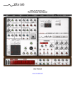
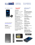
Figure 1-1
10
H0407-1030 Model 407K_44640-01RevA 5-5x7-5.qxd 8/23/10 2:00 PM Page 11
Model 407A Specifications
Physical Specifications
Specification
Wavelength Range
250 nm to 11µm
Power Range
Continuous
<5 mW to 20W
Intermittent
Up to 30 W
Max Power Density
20 KW/cm2
Detector Diameter
1.8 cm
Sensitivity Variation
400 - 100 um
±1%
250nm – 11 um
±3%
Calibration Accuracy
For 1 W @ 810 nm
±1%
Detector Spatial Sensitivity Variation
(using a 2mm beam)
±2.5%
Maximum pk-pk Noise & Zero Drift per Minute
1 W scale
<0.2% full scale
30 mW scale
<2% full scale
Meter Time Constant
1 W scale or higher
<0.5 sec
30 mW scale
< 1 sec
Meter Ranges
30 mW, 100 mW, 300mW, 1W, 3W, 10W, 30W
Battery Charge
60 hr (minimum)
Electrical Requirements
Model 407A-1
90-132 Vac, 50-60 Hz
Model 407A-2
198-264 Vac, 50 Hz
11
H0407-1030 Model 407K_44640-01RevA 5-5x7-5.qxd 8/23/10 2:00 PM Page 12
Physical Dimensions
Display
Detector Head
Width
17.5 cm (6.8 in.)
6.3 cm. Dia. (2.5 in.)
Height
9.5 cm ( 3.75 in.)
Adjustable from 8.9 to 21.1
cm (3.5 to 8.3 in.)
(to center of detector)
Length
5.8 cm (2.28 in.)
3.4 cm (1.3 in.)
Weight
0.6 kg (1.4 lbs.)
0.3 kg (0.7 lbs.)
Outline Drawings
Distance to Detector Surface (D)
Height (H)
Non-Pulsed
0.42
Post
Min
Max
Pulsed
0.37
Short
3.5
5.3
Medium
5
6.8
Tall
6.5
8.3
12
H0407-1030 Model 407K_44640-01RevA 5-5x7-5.qxd 8/23/10 2:00 PM Page 13
2
Laser Safety
CAUTION
While the Model 407A does not emit laser radiation, it is
designed to work with Class IV High Power Lasers, whose
beams are, by definition, safety and fire hazards. Take precautions to prevent accidental exposure to both direct and
reflected beams. Diffuse as well as spectacular reflections, can
cause severe eye or skin damage.
Precautions for the Safe Operation of Class IV
High Power Lasers
•
Keep the chassis housing and covers on the laser and the Model
407A at all times.
•
Avoid looking at the laser output beam; even diffuse reflections,
for example off the detector surface, are hazardous.
•
Use protective eyewear at all times; selection depends on the
wavelength, and the visual function required. Consult the ANSI,
ACGIH, or OSHA standards listed at the end of this section for
guidance on eye wear selection.
•
Reduce the laser output power while aligning the Model 407A to
the beam. Beware of reflections from the Model 407A heat sink.
•
Avoid blocking the laser output beam or its reflection with any
part of the body.
•
Establish a controlled access area for laser operation. Limit
access to those trained in the principles of laser safety.
•
Post prominent warning signs near the laser operation area.
•
Set up experiments so that the laser beam is not at eye level.
•
Provide enclosures for beam paths whenever possible.
•
Set up shields to prevent or block unnecessary specular reflections.
•
Set up an energy absorbing target to capture the laser beam,
preventing unnecessary reflections or scattering.
13
H0407-1030 Model 407K_44640-01RevA 5-5x7-5.qxd 8/23/10 2:00 PM Page 14
For information on regulations for laser safety, consult the United
States code of Federal Regulations: Title 21, Chapter 1, Subchapter J,
Parts and 1040.10 and 1040.11 as applicable. The Center for Devices
and Radiological Health (CDRH) is the governing regulatory agency.
Sources of Laser Safety Standards
“Safe Use of Lasers” (Z1236.1)
American National Standards Institute (ANSI)
1430 Broadway
New York, NY 10018
“A Guide for Control of Laser Hazards”
American Conference of Governmental and Industrial Hygienists
(ACGIH)
1014 Broadway
Cincinnati, OH 45202
Occupational Safety and Health Administration (OSHA)
U.S. Department of Labor
400 1st Street N. W.
Washington, C.C. 20001
14
H0407-1030 Model 407K_44640-01RevA 5-5x7-5.qxd 8/23/10 2:00 PM Page 15
3
Installation
Unpacking Your Power Meter
When ordered as a complete set, the Model 407A comes with the following components:
•
Readout Assembly
Readout
Cable, BNC, 5 foot length
Power Supply/Charger, 117 Vac or 220 Vac
•
Detector Head Assembly
Detector Head
Detector Base
Detector Posts, 1/4 - 20 tapped, 1/2 inch O.D., 2”, 4”, and 6”
•
Instruction Manual
•
Shipping and Storage Container
If readout assembly or head assembly is ordered separately, it will be
shipped in a standard shipping container.
Assembly
The Model 407A comes with a power supply in one of two standard
voltages. During use the power supply should be powered with
proper ac voltages and plugged into the Model 407A readout in order
to fully charge the rechargeable battery. Normal recharge time for the
battery is 14-16 hours. Once the battery charger/power supply is
plugged in, the Model 407A panel lights will be energized. The lights
will stay lit as long as the unit is plugged in. If the light must be off
or if portable operation is desired, the Model 407A can be operated
without its charger for up to 60 hours (on a fully charged and healthy
battery).
The Model 407A comes to you pre-calibrated at the factory. We use
an NIST-traceable standard detector at 810 nm, as a laboratory calibration reference from which all units are calibrated
Select the telescoping 1/2 inch diameter post which is appropriate for
your laser set up. Note that the rods are compatible with standard laboratory mounting rods and can be used in combination with any exist-
15
H0407-1030 Model 407K_44640-01RevA 5-5x7-5.qxd 8/23/10 2:00 PM Page 16
ing hardware. Observe that the rod can be threaded onto 1 of 2 different 1/4-20 UNC threaded studs located 180 degreed apart on the
detector head. This feature allows the user to conveniently work with
beams incident from either the left or right because the cable can be
routed to the front or rear as necessary.
If the telescoping rods are too long for a tight space, the head has
flats onto it which facilitate placing it directly on any flat surface.
The beam height above the flat to the detector centerline is 1.18
inches.
4
Operation
Location and Description of Controls
Side Panel Controls
REC OUT: A standard BNC type connector be can be attached in
order to display the output signal on a oscilloscope or a strip chart
recorder or can serve as an input to a computer’s A/D channel. The
output impedance is 10 KV. The range is 0-1 volts with 1 volt representing the full scale value on the analog meter.
CHARGE: A 15 volt direct current power supply is supplied standard
with all Model 407A power meters. Two variations are supplied—a
110 volt ac supply for U.S.A., Canada and Japan, and a 220 volt ac
for Europe (in U.K., contact your local Spectra Physics office for
availability of domestic power supplies). See Chapter 6 for ordering
information and part numbers. It is recommended that the supply is
left plugged in during normal operation. The Model 407A has been
designed to permit indefinite battery charging without damage to batteries or the charging circuit.
NOTE
If you desire NOT to have the meter illuminated you must
unplug the supply. A separate light switch was not supplied in
order to avoid inadvertent draining of the battery by using the
lights without the charger operating.
16
H0407-1030 Model 407K_44640-01RevA 5-5x7-5.qxd 8/23/10 2:00 PM Page 17
HEAD: The detector head uses a standard BNC type connector which
connects to the bottom jack labeled HEAD. Inadvertent cross connecting between the HEAD and RECOUT should be avoided, but
should cause no harm to the Model 407A.
ZERO: The zero knob is connected to a 10 turn potentiometer. The
zero adjust circuit has been carefully designed so that once the meter
has adjusted to read zero on the most sensitive scale, the readout will
be correctly zeroed for all other scales (the mechanical meter zero,
described below, must also be properly adjusted). Re-zeroing as
scales are changed is thus unnecessary. Note however, that on the
most sensitive scales some drift will occur if the detector is subjected
to thermal variations such as air drafts.
Front Panel Controls
BATT LOW: If the Model 407A is used without its charger, the BATT
LOW light will begin to blink (Approximately once every two seconds) when the battery has drained to the point that it must be
recharged. At this time you should plug the charger into a wall outlet
and connect the charger plug to the receptacle on the side of the 407A
display unit. The 407A may continue to be used while the battery is
charging. If the LED has been blinking some time before battery is
recharged, the LED may continue to blink for several minutes after the
charger is plugged in while battery voltage increases.
A full charge normally requires 14 hours with the 407A’s range selector switch in the OFF position, and 16 hours otherwise.
Although a blinking BATT LOW light indicates the need for a
recharge, you can safety operate your 407A an additional 20 minutes
before connecting the charger. Exceeding this time can have two
effects: Loss of accuracy (which will be most noticeable on the lowest
range setting) and possible shortening of battery life. Full discharge
of the battery should be avoided. Multi-cell nickel-cadmium batteries
such as the one provided with your Model 407A are prone to damage
from cell reversal, a phenomenon which occurs when such batteries
are taken into deep discharge while under load.
POWER RANGE SELECTOR SWITCH: The front panel knob has a
total of 8 positions, including an OFF position. The meter should
always be turned off when not in use in order to avoid battery drain.
17
H0407-1030 Model 407K_44640-01RevA 5-5x7-5.qxd 8/23/10 2:00 PM Page 18
During use always adjust the scale setting starting from higher value
scales in order to avoid unnecessary overdriving of the needle to
beyond full scale.
MECHANICAL METER ZERO: Directly below the meter is a screw
which allows the needle to be adjusted to read zero when the meter is
off. Normally the adjustment is not necessary but should be checked
when the 407A is first uncrated, and occasionally thereafter. This
adjustment I prerequisite to proper operation of the side panel zero
knob.
Rear Panel Controls
CALIB: A 1/8-inch wide screwdriver will permit adjustment of the
meter output. Adjustments should only be attempted in conjunction
with the instructions given in Chapter 5 of this manual.
SPEED: An access hole on the back panel allows the meter speed up
circuit to be adjusted to suit individual preference. The potentiometer
has been factory adjusted so that the response give maximum settling
time and will give needle overshoot of about 1 to 2 percent, when the
detector is suddenly exposed to an optical input.
The output signal from the head does not rise instantaneously when
the detector is exposed to a laser beam. Due to the mass of the
absorbing material to which the thermopile is attached, the output rise
in an exponential manner with a time constant (0-63 percent of final
value) of about 1 second. Several seconds are required for the output
to stabilize at its final value. Treating the output rise as purely exponential, an estimate of final value can be made very quickly by passing the signal through a compensating network in the display which is
adjusted to match the detector’s time constant. In this way, a final
value can be determined and displayed in about one second.
Two drawbacks occur to this speeding up of the output signal. Abrupt
changes in the signal applied to the compensating network, which
occurs when adjusting the ZERO control and when changing scales,
cause the meter response to exhibit overshoot. Also, noise in the circuit is accentuated over that seen without the compensating network.
18
H0407-1030 Model 407K_44640-01RevA 5-5x7-5.qxd 8/23/10 2:00 PM Page 19
Operating Instructions
The Model 407A was designed for ease of operation. During normal
operation only initial zeroing of the meter and power range selection is
required.
Turning on the Model 407A
The Model 407A will arrive with the battery in a partially or completely charged condition. The charging circuit is designed not to
damage the battery even during extended charging periods. Therefore
we recommend that the user normally leave the power supply plugged
into the Model 407A and into an ac power source.
Input signals not derived from the head may cause rapid but momentary needle motion due to the influence of the anticipation circuit.
Examples include scale changes and zeroing the meter. This behavior
is normal.
Zeroing Procedure
1.
While the meter selection knob is in the OFF position, verify that
the meter needle points to zero. If adjustment required, rotate the
screw on the front panel of the readout to zero the needle.
2.
Plug in the detector head to the readout jack marked HEAD using
the BNC cable provided. The head should ideally be placed in
the location where actual measurements will be made, but without any optical radiation applied.
3.
Rotate the power range knob to the 30mW setting. Adjust the
zero position as required using the zero adjust knob on the right
side panel. Once the most sensitive range has been adjusted, all
higher ranges will accurately read zero as well – provided that the
mechanical zero has been adjusted correctly with the display
turned OFF.
19
H0407-1030 Model 407K_44640-01RevA 5-5x7-5.qxd 8/23/10 2:00 PM Page 20
NOTE
If the 407A is to be used on the 30 mW or 100 mW scales, the
detector may be sensitive to temperature fluctuations caused
by air currents or air temperature change. Therefore, care
should be taken to ensure that the detector is not subject to
such fluctuations. If necessary re-zero the readout.
Reading the Meter
The Model 407A features a taut-band style analog meter for the
fastest and most sensitive response. An “anticipation” circuit is
included which speeds up the natural response time of the detector.
The circuit normally provides a small amount or overshoot. If the
needle response is too fast or too slow for your needs, the SPEED
control may be adjusted. See Chapter 5 for the adjustment procedure.
Warning on Measuring Pulsed Lasers
Your Model 407A CW head is not designed to monitor pulsed lasers.
Even though average output power may be low, the high energy, high
peak power pulses from some lasers (Q-switched lasers, for example) can
cause irreversible damage to the detector in the Model 407A due to
excessive instantaneous local heating of the detector surface. Pulsed laser
power is best measured using a detector designed for that application.
NOTE
Replacement of the detectors which have been damaged by
pulsed laser beams is not covered under warranty.
Use the following peak power density specifications to help you
decide if the Model 407A is suitable to use in your application.
Specification
Max Peak Energy Density
(50 nsec pulse)
Model 407A
0.3 J/cm2
The Model 407A is NOT recommended for use with low repetition
rate, high energy pulsed lasers. Consult Newport about your particular application before monitoring pulsed lasers.
20
H0407-1030 Model 407K_44640-01RevA 5-5x7-5.qxd 8/23/10 2:00 PM Page 21
Limitations on Use of Thermal Detectors
Thermal Detectors convert light into heat which in turn generates a
change in temperature. In case of thermopiles the change in temperature is relative to a second set of junctions held at a reference temperature. This is significant for two reasons. First, if the reference temperature itself changes then the output signal may contain a spurious
component. For instance, if the detector is subjected to high incident
power for a prolonged period the entire head – including the reference
junctions—will warm up. If the detector then is subjected to a weak
incident beam, the power reading may drift as the reference junction
adjusts to a cooler equilibrium state. This effect is temporary and may
only be noticeable with power changes of 1 to 2 orders of magnitude.
The second limitation to thermal detectors is that they respond to any
heat source – not only lasers. This effect can be noticed on the most
sensitive (30mW, 100mW) scales. Noise in the form of drift or slow
random motion can be caused by simply grasping the cooling fins
with a hand or by blowing on the detector (not recommended). A
more serious nuisance is drafts with the lowest scale take care to
shield the detector head from large drafts.
21
H0407-1030 Model 407K_44640-01RevA 5-5x7-5.qxd 8/23/10 2:00 PM Page 22
5
Calibration
Introduction
Your Model 407A is calibrated at the factory with 1 watt of laser
power at 810 nm. If re-calibration is ever required, the procedures
given in this chapter allow you to work on your own. Power is generally applied to the detector in form of laser radiation. Sensitivity is
adjusted with CALIB control and meter response rate is set with
SPEED control. Both controls are accessible through the rear cover
of the display unit.
Equipment Required
•
Laser operating at desired wavelength and power (good intensity
stability makes the job easier)
•
Laser goggles (as required)
•
Reference standard power meter calibrated at desired wavelength
and power
•
Screwdriver with 1/8’’ (3mm) wide blade
•
External laser beam block (for setting SPEED control)
CAUTION
Watch out for stray reflections!!
NOTE
Absorptance by the detector’s surface is a function of the laser
wavelength being measured (see Figure 1-1). This variation in
absorptance must be taken into account when making exacting
power measurements at wavelengths other than that at which
calibration is preformed.
22
H0407-1030 Model 407K_44640-01RevA 5-5x7-5.qxd 8/23/10 2:00 PM Page 23
Procedure
1.
Set up the laser to operate at the desired wavelength and power.
Verify power with a calibrated reference standard power meter.
2.
Set up your Model 407A so that the meter is easily readable and you
have easy access to the CALIB and SPEED controls in the back of the
display unit. A mirror can be used to view the meter while adjusting
the controls. The meter has a mirrored scale to prevent parallax error
during reading.
3.
Check the mechanical zero of the 407A’s meter while the unit is OFF.
4.
Rotate the 407A’s rotary switch to the 1 W setting (1 W calibration is
assumed in this procedure).
5.
Align the 407A’s meter pointer with “0” on the upper scale by adjusting the ZERO control.
6.
To adjust the meter, place the detector head in the path of the laser
beam and allow the meter reading to stabilize. Adjust the CALIB
control to give full upper scale deflection of the meter pointer (i.e.,
pointer aligned with “10”). The CALIB control is accessible through
the rear panel of the display unit with a 1/8’’ (3mm) wide blade screwdriver. Clockwise rotation of the control (when viewed from rear
cover) increases the meter reading.
7.
Block the laser beam and let the meter pointer return to “0”. Due to
cooling of the head you may have to wait a minute to allow the meter
reading to settle to its final value. Adjust the ZERO control if necessary.
8.
Remove the beam block once again and verify the meter reading for
laser power.
9.
Recheck the meter zero (block the beam).
10.
Meter response rate can be varied by adjusting the SPEED control.
This control is accessible through the rear cover to the display unit.
For heads and displays sold together as matched serial numbers, the
SPEED control is adjusted at the factory to give 1 to 2 percent overshoot in the meter’s response.
This amount of overshoot allows reasonable meter response rate with
minimum settling time and provides acceptable noise performance at
low power settings.
23
H0407-1030 Model 407K_44640-01RevA 5-5x7-5.qxd 8/23/10 2:00 PM Page 24
The SPEED control can be adjusted as follows:
11.
a.
Set the laser power to give meter pointer deflection of approximately 90 percent full scale (upper scale).
b.
Block the laser beam and let the meter reading return to zero.
c.
Unblock the beam and note the meter response. Overshoot can
be measured by counting the small divisions on the upper scale
between the maximum pointer excursion and the final resting
position. Each small division on the upper scale corresponds to
2 percent of the full scale. For example, 2 divisions of overshoot
corresponds to 4 percent overshoot.
d.
Adjust the SPEED control to give the desired meter response rate.
Clockwise rotation of the control (when viewed from the rear
cover) gives faster meter response to change in detector heating.
Check laser power again with the reference standard meter.
24
H0407-1030 Model 407K_44640-01RevA 5-5x7-5.qxd 8/23/10 2:00 PM Page 25
6
Service and Repair
Introduction
Your Model 407A requires no routine maintenance. Newport does not
recommend user repair of this product. If your unit needs repair, we
recommend that you return it to the nearest Newport Service Center.
However, we recognize that there may be times when return of the
unit to a repair facility might pose a hardship or inconvenience. For
this reason, we provide the following technical description for changing the meter lamps and the rechargeable battery (these components
are expected to have at least 5 to 10 year service life). No other components should ever require replacement in normal operation.
Note that if the detector disk becomes damaged, the power meter readout and head should be returned together to your local Newport
Service Center.
Replacement Items
The 5 foot (1.5 m) connecting cable between detector head and the
display unit has male BNC terminations and uses RG174/U cable.
Newport part number: 6015-0290.
Two types of battery chargers are sold with the Model 407A:
Voltage
Line Frequency
Spectra Physics
Part Number
90-132 Vac
50/60 Hz
90036748
198-264 Vac
50 Hz
4004-0602
25
H0407-1030 Model 407K_44640-01RevA 5-5x7-5.qxd 8/23/10 2:00 PM Page 26
Cleaning Your Unit
Should your power meter display unit need cleaning, please observe
the following precautions:
•
Clean the meter face with a mild detergent and a moist (not wet)
SOFT CLOTH to avoid scratching the plastic face; do not use
solvents.
•
Do not allow solvents to come in contact with the plastic knobs.
•
Do not attempt to clean the surface of the detector in the head.
CAUTION
Only experienced service professional should attempt the following procedures. For field replacement of the meter lamps
or battery, refer to the work to a qualified service professional,
experienced in repairing instruments of this type.
Opening the Display Unit
Should you need to replace the meter lamp or the battery, use the following procedure to open the unit and access the circuit board. Take
care not to scratch the plastic meter face.
Tools Required
•
•
•
•
1/4’’ nut driver (3/8’’OD socket), or a wide blade screwdriver
#1 Phillips screwdriver
1/16’’ hex driver
5/64 hex driver
Procedure
1.
Set the rotary switch to the OFF position.
2.
Pry the cap from the ZERP knob and use the 1/4” nut driver or a
flat blade screwdriver to loosen the collet nut. Remove the
ZERO knob.
3.
Remove the screws from the back cover. Corner screws are 3
mm Phillips head while those in the central area are #4-40 Button
head or Torx head, depending on the model and serial number.
26
H0407-1030 Model 407K_44640-01RevA 5-5x7-5.qxd 8/23/10 2:00 PM Page 27
4.
Remove the black flat head screw (36-32) and washer from the
bail on that side of the unit in which the BNC receptacles and the
charger jack are located.
5.
CAREFULLY tip the housing over just enough to allow one end
of the circuit board to swing out of the housing. Grasp the circuit
board by its edges and continue to swing the board until the
rotary knob clears the housing. Avoid touching the circuitry on
the board so as not to contaminate it with finger oils. Now,
slowly pull the board out of the housing, being careful not to
break the wire leads which connect the circuit board to the panel
meter. The metal nut bracket will fall loose at this time.
WATCH THAT YOU SO NOT DISTURB THE SETTINGS OF
THE POTENTIOMETERS LOCATED ON THE SOLDER
SIDE OF THE BOARD.
6.
Taking care not to damage the meter face, set the housing to one
side and position the board so that it rests on its standoffs on a
smooth non-conductive surface.
Should the wire leads between the circuit board and the meter break,
you may carefully solder them back in place. If you need to solder
one of the meter terminals, clamp the terminal with a hemostat below
the point at which you want to solder. The hemostat will act as a heat
sink and prevent softening of the meter case at the entry point of the
terminal. On the circuit board end, the red wire is connected at the
hole marked “M2+” and the black wire is connected at the hole
marked “M1-”. Do not apply excessive heat to the circuit board as this
may cause lifting of the pads and traces.
Reassembling the Display Unit
1.
Make sure that the rotary switched on the circuit board is in the
OFF position (fully counterclockwise).
2.
Pick up the circuit board by its edges and orient it so that the
component side faces the inside of the housing. WATCH THAT
YOU DO NOT DISTURB THE SETTINGS OF THE POTENTIOMETERS LOCATED ON THE SOLDER SIDE OF THE
BOARD. Take care not to break the wire leads which connect
the circuit board to the panel meter.
27
H0407-1030 Model 407K_44640-01RevA 5-5x7-5.qxd 8/23/10 2:00 PM Page 28
3.
Fit the metal nut bracket over the end of the board which contains the BNC receptacles and the charger jack; the bracket’s tab
rests in the shallow cutout at that end of the board. Make sure
that the piece of Kapton insulating tape is still on the underside
of the bracket, facing the solder side of the board.
4.
Keeping a finger on the nut bracket, slide the circuit board sown
into the housing at an angle. Insert the BNC receptacles and the
charger jack into the holes provided in the wall of the housing.
Continue to push the board until it stops against the wall of the
housing. At this point, check to see that the meter lights will
slide down between the panel meter and the housing. Also make
sure that the BATT LOW LED is straight in its socket. The rest
of the board now should be free to fall into place in the housing.
While swinging the board into place, make sure that the BATT
LOW LED fits into the hole provided for it in the front surface of
the housing.
NOTE
If for some reason, the LED is removed from its socket, it
needs to be reinstalled, the flat index mark on the LED should
face AWAY from the rotary switch.
5.
On the outside of the housing above the charger jack, insert the
black plastic washer between the bail and the housing. Then
insert the black flat head screw enough to engage it in the threads
of the nut but do not tighten it yet.
6.
Replace the back cover and loosely install the 4 button head
screws through the central holes and into the threaded standoffs
of the circuit board inside.
7.
Reinstall the ZERO control knob on the shaft letting 7/16’’ (11m)
of the knob’s end protrude from the outside wall of the housing.
Replace the knob cap at this time.
8.
Position the circuit board using the BNC receptacles and the
ZERO knob so that the ZERO and the rotary switch knobs are
able to rotate freely in their holes. Then tighten the 4 button head
screws.
28
H0407-1030 Model 407K_44640-01RevA 5-5x7-5.qxd 8/23/10 2:00 PM Page 29
9.
At the end of the housing which contains the metal nut bracket,
install 2 of the 3 mm Phillips head screws at the corners of the
back cover, engaging the nuts in the bracket inside. Tighten the
screws evenly in order to keep the bracket inside as level as possible.
10. Install the remaining 3mm Phillips head screws in the corners of
the cover.
11. Tighten the black flat head screw which retains the bail.
Replacing Meter Lamps
The meter is illuminated by two lamps when the charger is plugged
in. To change lamps, follow the procedures given above for removing
the circuit board from its housing. Then unplug the lamps from their
socket and replace with new ones. We recommend that you replace
both lamps at the same time. Reassemble the unit using the procedure above.
The meter lamps are General Electric equivalent #8099 Newport part
number: 3901-2040.
Replacing the Battery
When the battery no longer holds a charge, or when the BAT LOW
LED blinks continually even with the charger plugged in, the battery
should be replaced.
Not all “9 volt” Nickel-Cadmium rechargeable batteries are equivalent. Battery voltages of 8.4 and 7.2 volts are common. Due to differing internal cell construction, battery capacity and durability may
vary between battery types. The battery recommended by Newport is
not damaged when the charger is left plugged into the display unit for
long periods of time.
Newport recommends the following replacement battery for the
Model 407A:
Varta #V7/8R 8.4 volts, 100mAh
Newport part number: 4006-0290
In replacing the battery, follow the procedure given above for removing the circuit board from its housing and for reassembling the unit.
29
H0407-1030 Model 407K_44640-01RevA 5-5x7-5.qxd 8/23/10 2:00 PM Page 30
WARNINGS
DO NOT incinerate or mutilate batteries;
they will burst or release toxic materials.
DO NOT short circuit batteries; this may cause burns.
Old and new batteries may be partially charged.
Be cautious during battery replacement and disposal.
WARNING
Do not attempt to use a NiMH battery in your Model 407A
Instrument. The charging circurity only supports NiCd chemistry batteries and there is a severe risk of explosion or fire if a
NiMH-Chemistry battery is substituted
CAUTION
The use of shatterproof protective eyewear is recommended
for the following steps
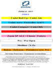
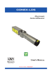
Figure 6-1
1.
Make sure that the rotary switch is in the OFF position (most
counterclockwise). Unplug the battery from its mounting
bracket terminals. The circuit board has a hole drilled in it
between the battery terminals. A suitable stiff insulated rod may
be inserted through the mounting bracket and anchored in the
hole. Then the rod can be pulled back as a lever to separate the
battery from the bracket’s terminals. A 3/32’’ flat blade screwdriver, with 3’’ long blade insulated with a piece of shrink tubing
works well as a rod.
30
H0407-1030 Model 407K_44640-01RevA 5-5x7-5.qxd 8/23/10 2:00 PM Page 31
2.
Remove the battery from the mounting bracket’s clip as shown in
Figure 6-1. Use a thumb or forefinger of one hand to pull back
one side of the clip and use the fingers of the other hand to rotate
the battery and pull it out of the clip. The clip is rather stiff so be
careful no to hurt your fingers or fingernails. Be careful not to
break the wire connections from the circuit board to the panel
meter. Avoid touching the circuitry on the board so as to not
contaminate it with finger oils.
3.
Cover the terminals of the old battery with nonconductive tape
(such as the vinyl tape used by electricians) and dispose of the
battery following local ordinances.
4.
Use a similar procedure as in Step 2 to install the new battery in
the mounting brackets clip. Use caution since the battery may be
charged.
5.
Reconnect the battery to the bracket’s terminals. Use one hand
to grasp the circuit board by the edges. Use the index and the
middle fingers of the other hand to restrain the battery mount’s
terminals while pushing on the end of the battery with the thumb
of that same hand.
6.
Reinstall the circuit board following the procedure given in the
section at the beginning of this chapter.
WARNING – Battery Disposal
DO NOT PLACE USED BATTERIES INTO THE
NORMAL WASTE DISPOSAL STREAM.
Cd
The Model 407A’s battery contains Cadmium, a
heavy metal that can have serious environmental
impacts if it is placed into the normal waste disposal stream. For this reason, used batteries must
be separated from normal trash and recycled.
Dispose of used batteries in accordance with local waste regulations. Within the European Union and other jurisdictions
with mandated “Take Back” regulations , contact your local
Newport sales office or representative for information on
where to send used batteries for proper disposal and recycling.
31
H0407-1030 Model 407K_44640-01RevA 5-5x7-5.qxd 8/23/10 2:00 PM Page 32
7
Customer Service
Introduction
To obtain information regarding factory service, contact Newport
Corporation’s Service Department or your Newport representative.
Please have the following information available:
•
Instrument model number (on the rear panel)
•
Instrument serial number (on rear panel)
•
Description of the problem
•
Your contact information
To help our Technical Support Representatives diagnose your problem, please note the following conditions:
•
Is the system used for manufacturing or research and development?
•
What was the state of the system right before the problem?
•
Have you seen this problem before? If so, how often?
•
Can the system continue to operate with this problem? Or is the
system non-operational?
•
Can you identify anything that was different than before this
problem occurred?
32
H0407-1030 Model 407K_44640-01RevA 5-5x7-5.qxd 8/23/10 2:00 PM Page 33
Technical Support Contacts
North America & Asia
Newport Corporation Service Dept.
1791 Deere Ave. Irvine, CA 92606
Telephone: (949) 253-1694
Telephone: (800) 222-6440
Europe
Newport/MICRO-CONTROLE S.A.
Zone Industrielle
45340 Beaune la Rolande, FRANCE
Telephone: (33) 02 38 40 51 56
Asia
253 Aidu Road, Bld #3, Flr 3, Sec C
Shanghai 200131, China
Telephone: +86-21-5046 2300
Fax: +86-21-5046 2323
Newport Corporation Calling Procedure
If there are any defects in material or workmanship or a failure to meet specifications, promptly notify Newport's Returns Department by calling
1-800-222-6440 or by visiting our website at www.newport.com/returns within the
warranty period to obtain a Return Material Authorization Number (RMA#). Return
the product to Newport Corporation, freight prepaid, clearly marked with the RMA#
and we will either repair or replace it at our discretion. Newport is not responsible
for damage occurring in transit and is not obligated to accept products returned without an RMA#.
E-mail: [email protected]
When calling Newport Corporation, please provide the customer care representativewith the following information:
• Your Contact Information
• Serial number or original order number
• Description of problem (i.e., hardware or software)
To help our Technical Support Representatives diagnose your problem, please note
the following conditions:
•
•
•
•
Is the system used for manufacturing or research and development?
What was the state of the system right before the problem?
Have you seen this problem before? If so, how often?
Can the system continue to operate with this problem?
Or is the system non-operational?
• Can you identify anything that was different before this problem occurred?
33
H0407-1030 Model 407K_44640-01RevA 5-5x7-5.qxd 8/23/10 2:00 PM Page 34
Service Form
Newport Corporation
USA Office 800-222-6440
FAX: 949-253-1479
Name ____________________________
Return Authorization # ____________________
(Please obtain RA# prior to return of item)
Company ____________________________________________________________________
Address __________________________________________Date ______________________
Country ________________________________Phone Number ________________________
P.O. Number______________________________Fax Number __________________________
Item(s) Being Returned:
Model # ________________________________Serial # ______________________________
Description __________________________________________________________________
Reason for return of goods (please list any specific problems):
____________________________________________________________________________
____________________________________________________________________________
____________________________________________________________________________
____________________________________________________________________________
____________________________________________________________________________
____________________________________________________________________________
____________________________________________________________________________
____________________________________________________________________________
____________________________________________________________________________
____________________________________________________________________________
____________________________________________________________________________
34
H0407-1030 Model 407K_44640-01RevA 5-5x7-5.qxd 8/23/10 2:00 PM Page 35
35
H0407-1030 Model 407K_44640-01RevA 5-5x7-5.qxd 8/23/10 2:00 PM Page 36
Newport Corporation
Worldwide Headquarters
1791 Deere Avenue
Irvine, CA 92606
(In U.S.): 800-222-6440
Tel: 949-863-3144
Fax: 949-253-1680
email: [email protected]
Visit Newport Online at: www.newport.com
Newport Corporation, Irvine, California, has been certified compliant with ISO 9001
by the British Standards Institution.