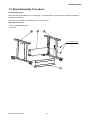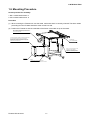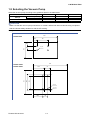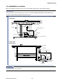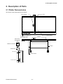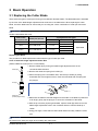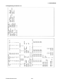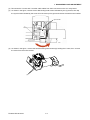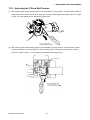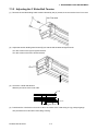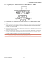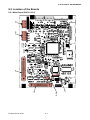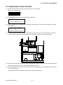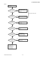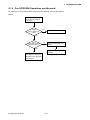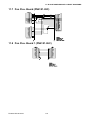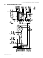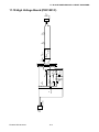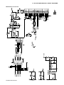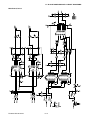
1
CUTTING MACHINE
FC2250
FC2250-UM-251-03-9370
SERVICE MANUAL
HISTORY OF REVISIONS
No. Date issued
Description of revision
1
07.10.10
First Printing
2
08.01.09 Parts number for the vacuum panels were corrected.
3
08.03.18 The dip switch setting for the Keyboard and Sensor Test
4
5
6
7
08.03.18
Mode was corrected.
Step (8) of figure was corrected.
FC2250-UM-251-9370
i
Page
All
10-1
8-4.8-17
Edition
01
02
03
8-17
03
CONTENTS
1. INTRODUCTION.............................................................1-1
1.1
1.2
1.3
1.4
1.5
1.6
1.7
1.8
1.9
Model Names and Basic Specifications .........................................................1-1
Standard Accessories ......................................................................................1-1
Main Specifications ..........................................................................................1-2
External Dimensions ........................................................................................1-3
Stand Assembly Procedure .............................................................................1-6
Mounting Procedure .........................................................................................1-7
Removing the Y Bar Retaining Brackets ........................................................1-8
Selecting the Vacuum Pump............................................................................1-9
Installation Location .......................................................................................1-10
2. Description of Parts ......................................................2-1
2.1
2.2
2.3
2.4
3
Plotter Nomenclature .......................................................................................2-1
Control Panel ....................................................................................................2-2
Types of Cutter Blades and Their Features....................................................2-4
Cutter Pen Nomenclature.................................................................................2-5
Basic Operation.............................................................3-1
3.1
3.2
3.3
3.4
3.5
3.6
3.7
3.8
3.9
3.10
3.11
Replacing the Cutter Blade ..............................................................................3-1
Adjusting the Blade Length .............................................................................3-4
Mounting the Cutter Pen ..................................................................................3-5
Adjusting the Pen Carriage Height .................................................................3-6
Turning On the Plotter and Initialization.........................................................3-7
Loading the Medium .........................................................................................3-8
PAUSE Menu Configuration.............................................................................3-9
Setting the Cutting Conditions ......................................................................3-10
Printing a Conditions List ..............................................................................3-12
Printing a Character Dump List .....................................................................3-14
Printing the Self-Test Pattern ........................................................................3-16
4. Daily Maintenance and Storage ...................................4-1
5. RECOMMENDED PARTS LIST .....................................5-1
FC2250-UM-251-9370
ii
6. LIST OF TOOLS .............................................................6-1
6.1
Tools ..................................................................................................................6-1
7. DISASSEMBLY AND ADJUSTMENT ............................7-1
7.1
7.1.1
7.1.2
7.1.3
7.1.4
7.1.5
7.2
7.2.1
7.2.2
7.2.3
7.3
7.3.1
7.3.2
7.4
7.5
7.6
7.7
7.8
7.9
7.9.1
7.9.2
7.9.3
Adjusting the X-Axis Drive...............................................................................7-1
Removing the X Motor Cover ................................................................................................................. 7-1
Adjusting the X Drive Belt Tension ........................................................................................................ 7-1
Adjusting the Belt Tension of the Front X Slider .................................................................................. 7-2
Adjusting the Belt Tension of the Rear X Slider ................................................................................... 7-2
Checking the Belt Tension of the Front and Rear X Sliders ................................................................ 7-3
Adjusting the Y-Axis Drive ...............................................................................7-4
Removing the Y Motor Cover ................................................................................................................. 7-4
Removing the Y Motor............................................................................................................................. 7-4
Adjusting the Y Drive Belt Tension ........................................................................................................ 7-6
Adjusting the Y Slider ......................................................................................7-7
Removing the Y Bar................................................................................................................................. 7-7
Adjusting the Y Slider Belt Tension ....................................................................................................... 7-8
Adjusting the Roller Pressure of the Front X Slider ......................................7-9
Adjusting the Roller Pressure of the Rear X Slider .....................................7-10
Adjusting the Roller Pressure of the Y Slider ..............................................7-12
Adjusting the Position of Sensor Dog Y.......................................................7-13
Mounting the Y Slider on the Y Flexible Printed Circuit Cable ...................7-14
Pen Block ........................................................................................................7-16
Removing the Pen Block Cover ........................................................................................................... 7-16
Removing the Pen Block ...................................................................................................................... 7-16
Adjusting the Pen Block ....................................................................................................................... 7-17
7.10 Using the Mechanical Adjustment Jigs ........................................................7-19
7.11 Replacing the Y Bar ........................................................................................7-19
7.11.1 Preparations........................................................................................................................................... 7-19
7.11.2 Replacing the Y Bar ............................................................................................................................... 7-20
7.11.3 Checking the Sliding of the Y Bar Frame (Manual Check)................................................................. 7-21
7.12 Adjusting the Perpendicularity Precision ....................................................7-22
7.12.1 Checking the Deviation in the Perpendicularity ................................................................................. 7-22
7.13 Replacing the Electrostatic Adhesion Plate .................................................7-24
7.13.1 Peeling Off the Electrostatic Adhesion Plate ...................................................................................... 7-24
7.13.2 Preliminary Preparations for Pasting On New Plate .......................................................................... 7-25
7.13.3 Attaching the Electrostatic Adhesion Plate ........................................................................................ 7-26
FC2250-UM-251-9370
iii
8. ELECTRICAL ADJUSTMENTS......................................8-1
8.1
8.2
8.3
8.4
8.5
8.6
8.7
8.8
8.9
8.10
8.11
8.12
8.13
8.14
8.15
8.16
9
Flowchart of the Adjustment Sequence ........................................................8-1
Location of the Boards.....................................................................................8-2
Explanation of the Values of the Main Board .................................................8-3
Setting the DIP Switches..................................................................................8-4
Updating the System Firmware .......................................................................8-5
Clearing the Non-Volatile RAM ........................................................................8-6
Adjusting the Home Position...........................................................................8-7
Adjusting the Pen Height .................................................................................8-8
Adjusting the Pen Force ..................................................................................8-9
Adjusting the Distance and the Perpendicularity Accuracy .......................8-11
Adjusting the Pen Interval .............................................................................8-14
Adjusting the Auto-Registration Mark Sensor Sensitivity ..........................8-16
Adjusting the Offset of the Auto-Registration Mark Sensor .......................8-17
Testing the Control Panel Keys and Home Sensors ...................................8-19
List of Items Requiring Readjustment ..........................................................8-21
About Start Up Mode ......................................................................................8-21
TROUBLESHOOTING....................................................9-1
9.1
9.1.1
9.1.2
9.1.3
9.1.4
9.1.5
9.1.6
9.2
9.3
9.4
9.5
9.6
Troubleshooting Flowcharts............................................................................9-1
Checking for Faulty Rotation of the Blade ............................................................................................ 9-1
The Cutting Media Cannot be Satisfactorily Cut .................................................................................. 9-2
Initialization is Abnormal ........................................................................................................................ 9-8
Pen UP/DOWN Operations are Abnormal.............................................................................................. 9-9
The X-axis Backlash is Excessive ........................................................................................................9-11
The Y-axis Backlash is Excessive ........................................................................................................ 9-12
The Plotter is Turned On But Doesn’t Operate ............................................9-13
Error Messages ...............................................................................................9-14
Error Messages in GP-GL Command Mode .................................................9-15
Error Messages in HP-GL Emulation Mode..................................................9-16
The Cutting Results are Unsatisfactory .......................................................9-18
FC2250-UM-251-9370
iv
10. PARTS LISTS ...............................................................10-1
10.1
10.2
10.3
10.4
10.5
10.6
10.7
Mainframe ........................................................................................................10-1
Stand ................................................................................................................10-3
Control Panel ..................................................................................................10-4
Control Unit .....................................................................................................10-5
X Drive Unit .....................................................................................................10-6
Y Drive Section ...............................................................................................10-9
Standard Accessories ..................................................................................10-12
11. BLOCK DIAGRAMS AND CIRCUIT DIAGRAMS ........ 11-1
11.1
11.2
11.3
11.4
11.5
11.6
11.7
11.8
11.9
11.10
11.11
11.12
11.13
Wiring Connection ..........................................................................................11-1
Key Relay Board (PR223281) .........................................................................11-2
Main Relay Board (PN6121-02B) ...................................................................11-3
X Relay Board (PN6121-11C) .........................................................................11-6
X Flex. Board (PN6121-03C)...........................................................................11-7
X-Y Relay Board (PN6121-04C)......................................................................11-8
Pen Flex. Board (PN6121-05C) ......................................................................11-9
Pen Flex. Board 1 (PN6121-06C) ...................................................................11-9
2-Pen Board (PN6121-08C) ..........................................................................11-10
High Voltage Board (PR31001C)..................................................................11-11
Main Board (PN6121-01C) ...........................................................................11-12
Power Relay Board (PN5042-04) .................................................................11-21
Miscellaneous ...............................................................................................11-22
FC2250-UM-251-9370
v
FC2250-UM-251-9370
vi
1. INTRODUCTION
1. INTRODUCTION
1.1 Model Names and Basic Specifications
Model
FC2250-60VC
FC2250-120MG
FC2250-120ES
FC2250-120VC
FC2250-180ES
FC2250-180VC
Media hold down method
Vacuum suction
Magnetic
Electrostatic adhesion
Vacuum suction
Electrostatic adhesion
Vacuum suction
Cutting area
610 (X) x 920 (Y) mm
1200 (X) x 920 (Y) mm
1740 (X) x 920 (Y) mm
1.2 Standard Accessories
Item
Power cable
Cutter pen set
Water based fiber-tip pen
Sheet holder plates
Hexagon wrench
Height adjustment plates
Durable flexible hose
Description
PPA31-CB15B, CB15U-2SP, CB15U-K30-5SP
KF552-BK
For MG models only (2 large, 2 medium, 4 small)
For M4 bolts
10 mm, 4 mm height
For VC models only, 1.5 m to 5 m (can expand/contract)
Connection bore diameter: Ø38mm (-60), Ø58mm (-120/180)
Hose band
For VC models only, Ø38mm (-60), Ø58mm (-120/180)
Vacuum pump installation base For VC models only
USB cable
CD-ROM
User’s manual, Driver, other software
Q’ty
1
1 set
1
1 set
1
1 of each
1
2
1
1
1
CAUTION
• The vacuum pump is an option. It is not provided with the VC models.
• Make sure that the vacuum pump used with a VC model is affixed with either a label showing compliance
with the relevant safety standard or with the CE marking.
FC2250-UM-251-9370
1-1
1. INTRODUCTION
1.3 Main Specifications
Configuration
Effective cutting area
Media hold-down method
FC2250-60VC
FC2250-120VC/MG/ES
FC2250-180VC/ES
Flatbed
610 x 920 mm
1200 x 920 mm
1740 x 920 mm
VC models: Vacuum suction, MG models: Magnetic,
Maximum cutting speed
Cutting force
ES models: Electrostatic adhesion
400 mm/sec (40-step range)
High force mode: 9.8 N (1 kgf) max : 40-step range 2 to 80
Minimum character size
Mechanical resolution
Programmable resolution
Distance accuracy
Perpendicularity
Repeatability
Number of pens/cutters
Cutter and pen types
Standard force mode: 4.9 N (500 gf) max : 40-step range 1 to 40
About 10 mm square (varies with the character font and cutting media)
0.0025 mm
GP-GL mode: 0.1/0.05/0.025/0.01 mm, HP-GLTM mode: 0.025 mm
Within 0.1% of the distance moved (plotter mode)
Within 0.5 mm/900 mm (plotter mode)
Within 0.1 mm (plotter mode)
2
Cutter blades: Supersteel
Cutting media
Pens: water-based fibertip, oil-based ballpoint, disposable ink pen*1
Marking film (vinyl, fluorescent, reflective), Stiff paper/card up to 0.5 mm
thick, Sandblast rubber sheets up to 1 mm thick, High-intensity reflective
Interfaces
Buffer memory
Command sets
LCD panel
Reg strat on mark reading
film. Polystyrene foam sheets
RS-232C, USB 2.0 (full speed); auto-switching
2 MB
GP-GL and HP-GLTM emulation
20 characters x 2 lines
Provided
function
Power supply
100-120 VAC, 50/60 Hz, 1.2 A max
Operating environment
Guaranteed precision
220-240 VAC, 50/60 Hz, 0.7 A max
10 to 35˚C, 35 to 75% RH (non-condensing)
16 to +32˚C, 35% to 70% RH (non-condensing)
operating environment
External dimensions
(H x W x D)
Horizontal 857 x 920 x 1285 mm 944 x 1568 x 1285 mm
Tilted
----*2
1687 x 1568 x 987 mm
Weight (including stand)
Approx. 58 kg
Approx. 69 kg
Option
Vacuum pump (Blower) [VC models only]
*1: Disposable ink pens cannot be used with the high-force pen (Pen 2 holder).
*2: The writing panel on VC models cannot be tilted.
FC2250-UM-251-9370
1-2
944 x 2068 x 1285 mm
1687 x 2068 x 987 mm
Approx. 74 kg
1. INTRODUCTION
1.4 External Dimensions
1285
FC2250-60VC
790
857
67
920
58
720
910
1040
Unit: mm
Dimensional accuracy: ±5 mm
FC2250-UM-251-9370
1-3
1. INTRODUCTION
FC2250-120
Unit: mm
162
72
1568
1100
Dimensional accuracy: ±5mm
1285
1687
944
877
67
1040
985
FC2250-120
101
526
FC2250-UM-251-9370
1-4
1. INTRODUCTION
FC2250-180
Unit: mm
162
72
2068
1600
Dimensional accuracy: ±5mm
1285
1687
944
877
67
FC2250-180
985
1040
101
526
FC2250-UM-251-9370
1-5
1. INTRODUCTION
1.5 Stand Assembly Procedure
Assembly Procedure
Attach the two center plates (3) to the stand leg (1), using the M6 x 15 bolts and the L wrench provided as
standard accessories.
Attach the center plates (3) to stand leg (2) in the same way.
Standard accessories
1. M6 x 15 hexagonal bolts: 8
2. L wrench
M6 x 15 hexagonal bolts
FC2250-UM-251-9370
1-6
1. INTRODUCTION
1.6 Mounting Procedure
Screws provided for assembly
1. M4 x 8 bind-head screws: 8
2. M3 x 8 bind-head screws: 6
Procedure
(1) When mounting the FC2250 unit onto the stand, make sure that it is correctly oriented. The three cables
protruding from the FC2250 should be at the control box side.
(2) Position the FC2250 so that the underside of the frame is mounted on top of the stand.
After the FC2250 unit has been mounted on the
stand, insert the cables protruding from the underside
into the control panel box.
The control panel box is affixed to the side of the stand with
four M3 x 8 screws at the top and two at the bottom.
To facilitate the mounting of the control box on the stand,
insert the screws into the stand side first, leaving a gap,
and then mount the control box.
FC2250 frame
Two L-shaped brackets
FC2250 frame
Two L-shaped brackets
Screw in the M4 x 8 screws into the
brackets from the underside.
There are two screws each at four
locations, for a total of eight screws.
Control box
Note:
The surface with the M3 tapping screws
is the surface on which the control box is mounted.
FC2250-UM-251-9370
1-7
1. INTRODUCTION
1.7 Removing the Y Bar Retaining Brackets
(1) Use the L wrench supplied as a standard accessory to loosen the M3 hexagonal bolts.
Front
Expanded view F
Turn the M3 bolts
counterclockwise
to loosen them
Turn the M3 bolts
counterclockwise
to loosen them
Retaining bracket FR
Retaining bracket FL
Turn the M3 bolts
counterclockwise
to loosen them
Expanded view F
Turn the M3 bolts
counterclockwise
to loosen them
(2) Loosen the M3 bolts as shown in the illustration above, and then move the FL and FR retaining brackets
to the front, in a horizontal direction. Next, pull the brackets out in an upward direction. Use the L wrench
supplied as a standard accessory.
Rear
Retaining bracket R
Expanded view R
Expanded view R
nuts
e plate
Move th edge.
ft
s.
le
e
M3 bolt
to th
the two
Tighten
Remove the M3 hexagonal bolts
Pull the bracket out in an upward direction.
The plate nuts are on the far side of the bolts.
Move the plate nuts as is to the left edge, and
then fasten in place with the M3 bolts that were
removed.
CAUTION (IMPORTANT)
Move the plate nuts inside the pressed aluminum
fitting to the left edge, and then tighten the M3 bolts.
(3) Loosen the two M3 hexagonal bolts as shown in the above diagram, and then pull bracket R out in an
upward direction.
FC2250-UM-251-9370
1-8
1. INTRODUCTION
1.8 Selecting the Vacuum Pump
Select the vacuum pump according to the guidelines listed in the table below.
Item
FC2250-60VC
FC2250-120VC
3
0.3
0.5
Airflow (m /min)
Ratings
Static pressure (kPa)
5.4
6.4
Hose connection bore
38 mm
50 mm
FC2250-180VC
0.5
6.4
50 mm
CAUTION
Make sure that the vacuum pump used with a VC model is affixed with either a label showing compliance
with the relevant safety standard or with the CE marking.
The figure below shows the dimensions of the vacuum pump installation base provided.
330
FC2250-60VC
42.5
40
190
196
76
4-�10
496
FC2250-120VC
FC2250-180VC
95
205
225
314
174.5
4-�12
4-�10
150.5
FC2250-UM-251-9370
83
1-9
1. INTRODUCTION
1.9 Installation Location
When connecting the vacuum pump to your cutting plotter, please refer to the following diagram.
CAUTION
The exhaust from the vacuum pump is hot, so do not place anything flammable near the exhaust port.
Failure to observe this precaution could cause a fire.
FC2250-60VC
CA2294-01
Hose band
Durable flexible hose
CA2294-03
Vacuum pump
Hose band
CA2294-02
Connect to the power outlet
FC2250-120VC
FC2250-180VC
CA2294-01
Hose band
Durable flexible hose
Vacuum pump
Hose band
Connect to the
power outlet
CA2294-02
CHECKPOINT
A vacuum pump is not provided.
FC2250-UM-251-9370
1-10
CA2294-03
2. Description of Parts
2. Description of Parts
2.1 Plotter Nomenclature
The names of the plotter parts are as follows.
Pen carriage
Y ber
Control panel
CHART HOLD key
(ES models only)
Writing panel
Tilt lever
Rear view of
the main box
Interface connector
Stand
Power inlet
USB interface
Power switch
RS-232C interface
FC2250-UM-251-9370
RS-232C
2-1
2. Description of Parts
2.2 Control Panel
Indicator Lamps
......................The POWER lamp remains lit (green) while the plotter is on.
...................The PROMPT lamp lights (red) when the plotter receives data that will cause
the pen carriage to move outside the effective cutting area or receives the
“Prompt Light” command (T) from the computer.
CHART HOLD
(ES [electrostatic adhesion] models only)
.............................................Press the [CHART HOLD] key to enable the electrostatic adhesion function
(the key’s lamp lights). Press it again to cancel the electrostatic adhesion
function (the lamp goes off).
Panel Keys
..................... Depending on the menu being displayed, these keys are used to:
• Load a group of cutting conditions retained in the plotter’s memory;
• Shift the cursor when setting a numeric value for a function;
• Select the desired submenu.
................. • All four keys are used to move the pen carriage when setting a function that
requires the specification of a coordinate position.
• The [
] and [
] keys are used to raise or lower the displayed numeric
setting of a function.
• The [
] and [
] keys are used to select the pen type when setting a group
of cutting conditions.
• Press the [
] key and the [ENTER] key concurrently to move the pen
carriage to the upper right position and facilitate loading of the cutting
medium.
......................... Used to repeat the cutting operation defined by the data in the plotter’s receive
buffer.
....................... Used to set the eight groups of cutting conditions retained in the plotter’s
internal memory or to select one group as the current cutting conditions.
......................... Used to select the desired menu screen for setting a function at the control
panel when the plotter is in PAUSE mode.
FC2250-UM-251-9370
2-2
2. Description of Parts
......................... Press the [PAUSE] key to select PAUSE mode (its green lamp lights).
Press it again to cancel PAUSE mode (the lamp goes off).
Depending on the menu being displayed, this key is used to:
• Temporarily suspend a cutting or plotting operation;
• Set functions at the control panel;
• Temporarily store data received from the computer in the plotter’s buffer.
......................... After setting a function at the display panel, press the [ENTER] key to register
your setting.
To reset the plotter, concurrently press the [ENTER] and [ORIGIN] keys.
......................... Runs a cutting test to check whether the currently selected cutting conditions
are compatible with the medium loaded.
......................... Used to move the origin point.
To reset the plotter, concurrently press the [ENTER] and [ORIGIN] keys.
FC2250-UM-251-9370
2-3
2. Description of Parts
2.3 Types of Cutter Blades and Their Features
CAUTION
• Handle cutter blades with care!
Supersteel blades
Blade type
Blade features
• Less expensive than other types of blades
CB15U (ø1.5)
• The maximum cutting distance is about 4000 m
(depending on the medium and cutting pressure
CB15U-K30 (ø1.5)
used).
• The spring ensures that the blade is lifted clear of
CB15U-SP (ø1.5)
the cutting medium when the pen is raised.
Note:
CB15U-K30-SP (ø1.5)
The CB15U-K30 and CB15U-K30-SP blades are
designed for use with thick media e.g. rubber for
CB09UA (ø0.9)
sandblasting.
CB30UC (ø3.0)
FC2250-UM-251-9370
2-4
2. Description of Parts
2.4 Cutter Pen Nomenclature
CAUTION
• Handle cutter blades with care!
Structure of the PHP31-CB09-HS Cutter Pen
(for cutter blades of 0.9 mm diameter)
Protective cap
Plunger
Holder A
Spring
Cutter blade*
Holder B
Plunger cap
Blade length adjustment knob (blue)
* The CB09UA supersteel blade is shown in the figure above.
Structure of the PHP31-CB15-HS Cutter Pen
(for cutter blades of 1.5 mm diameter)
Protective cap
Plunger
Holder A
Cutter blade* Holder B
Plunger cap
Blade length adjustment knob (red)
* The CB15U supersteel blade is shown in the figure above.
Structure of the PHP31-CB15B-HS Cutter Pen
(for cutter blades of 1.5 mm diameter)
Protective cap
Plunger
Holder A
Spring
Cutter blade*
Holder B
Plunger cap
Blade length adjustment knob (green)
* The CB15U-SP supersteel blade is shown in the figure above.
Structure of the PHP34-CB30-HS Cutter Pen
(for cutter blades of 3.0 mm diameter)
Cutter pen for 3.0-mm diameter blades fitted with a spring
Protective cap Spring
Cutter blade*
Plunger
* The CB30UC supersteel blade is shown in the figure above.
FC2250-UM-251-9370
2-5
Holder
Blade length adjustment knob (silver)
3. OPERATIONS
3 Basic Operation
3.1 Replacing the Cutter Blade
There are three types of cutter pen. Each type has different diameter blades. The blade diameter is indicated
by the color of the blade length adjustment knob as shown in the table below. When replacing the cutter
blade, check the table below to ensure that you are using the correct combination of cutter pen and cutter
blade.
CAUTION
Handle cutter blades with care!
Color of the
adjustment knob
Cutter pen part no.
Copmpatible blade types
Diameter
Blue
PHP31-CB09-HS
0.9 mm
Red
PHP31-CB15-HS
1.5 mm
Green
PHP31-CB15B-HS
1.5 mm
Silver
PHP34-CB30-HS
3.0 mm
Part no.
CB09UA
CB15U
CB15U-K30
CB15U-SP
CB15U-K30-SP
CB30UC
Material
Supersteel
Replacing the Blade
The procedure for blade replacement varies with the type of cutter pen used.
Color of the blade length adjustment knob: Blue
(PHP31-CB09-HS cutter pen for 0.9 mm blades)
1. Remove holder (B) by turning the blade length adjustment knob in the
Holder (B)
counterclockwise direction.
2. Remove the blade and spring from holder (A).
3. Attach the spring to the new blade. Next, with the tip of holder (A) facing
downward and at an angle as shown, insert the new blade with the spring into
the plunger.
Plunger
Holder (A)
(Inside plunger body)
4. Make sure the blade is inserted straight into the holder. If the blade is positioned
at an angle, gently tap the plunger to correct the orientation of the blade.
5. With the tip of holder (A) facing downward, replace holder (B) and then turn the
blade length adjustment knob in the clockwise direction until the blade tip is
visible.
6. Using your finger, check that the cutter blade rotates smoothly inside the cutter
pen.
CAUTION
Be careful not to stab your finger when handling the cutter blade.
FC2250-UM-251-9730
3-1
3. OPERATIONS
Color of the blade length adjustment knob: Red
(PHP31-CB15-HS cutter pen for 1.5 mm blades)
1. Remove holder (B) by turning the blade length adjustment knob in the
Holder (B)
counterclockwise direction.
2. Remove the blade from holder (A).
3. With the tip of holder (A) facing downward as shown, insert the new blade.
4. Make sure the blade is inserted straight into the holder. If the blade is positioned
at an angle, gently tap the plunger to correct the orientation of the blade.
Plunger
5. With the tip of holder (A) facing downward, attach the holder cap and then turn
the blade length adjustment knob in the clockwise direction until the blade tip is
visible.
6. Using your finger, check that the cutter blade rotates smoothly inside the cutter
Holder (A)
(Inside plunger body)
pen (be careful not to stab your finger at this time).
7. If the blade does not rotate smoothly or the blade falls off after attaching the
cutter pen to the pen carriage, the inside of the holder is insufficiently lubricated.
In this case, apply the grease provided to the three points indicated by arrows in
the figure.
CAUTION
Be careful not to stab your finger when handling the cutter blade.
Color of the blade length adjustment knob: Green
(PHP31-CB15B-HS cutter pen for 1.5 mm diameter blades fitted with a spring)
1. Remove holder (B) by turning the blade adjustment knob in the counterclockwise
Holder (B)
direction.
2. Remove the blade and the spring from holder (A).
3. With the plunger held at an angle, and with the plunger cap pointing upward,
insert the blade with its spring attached into the plunger. Take care that the spring
does not fall off the blade.
Plunger
Holder (A)
(Inside plunger body)
4. Make sure that the blade is inserted straight into the plunger. If the blade is
inserted at an angle, gently tap the plunger to correct the orientation of the blade.
5. With the plunger still in the upright position, insert the holder cap until you hear
it click into place. Turn the blade adjustment knob in the clockwise direction to
adjust the length of the blade.
CAUTION
Be careful not to stab your finger when handling the cutter blade.
FC2250-UM-251-9730
3-2
3. OPERATIONS
Color of the blade length adjustment knob: Silver
(PHP34-CB30-HS cutter pen for3.0 mm diameter blades fitted with a spring)
1. Turn the blade length adjustment knob to retract the cutter blade inside the
plunger.
Plunger
2. Remove the plunger by turning the plunger cap in the counterclockw seid rection.
3. Remove the cutter blade from the plunger.
Cutter blade
Spring
Plunger cap
4. Insert the replacement cutter blade with its spring attached inside the hole in the
plunger cap.
5. Attach the plunger to the plunger cap w th the cutter blade inserted into it by
lowering the plunger onto the plunger cap.
CAUTION
Be careful not to stab your finger when handling the cutter blade.
FC2250-UM-251-9730
3-3
3. OPERATIONS
3.2 Adjusting the Blade Length
CAUTION
Be sure to correctly adjust the blade length. If the blade length is too long for the thickness of the medium
being used, you may damage the writing panel and the blade.
Adjusting the Blade Length
(1) The blade length is adjusted by turning the blade adjustment knob (blue, red or
green).
• To extend the blade, turn the knob in the A direction.
• To retract the blade, turn the knob in the B direction.
Use the scale on the plunger cap to determine how far to move the blade.
• When the knob is turned the distance of one scale unit, the blade moves 0.1 mm.
• When it is given one full turn, the blade moves 0.5 mm.
B
A
(2) Align the blade tip with the tip of the cutter pen, and then extend the blade tip to suit
the thickness of the medium being used.
Obtaining the Correct Blade Length
(1) Assuming that the film thickness is “t”, the blade length should be equal to “l”. Make
sure that “l” is never greater than the combined thickness of the film and its backing
sheet.
Film
R t
Backing sheet
If the film thickness cannot be accurately determined, adjust the blade length by
gradually increasing it until only traces of the blade appear on the backing sheet
when a cutting test is executed.
FC2250-UM-251-9730
3-4
3. OPERATIONS
3.3 Mounting the Cutter Pen
When you are facing the pen carriage, the holder at the left is tool holder 1 and the holder at the right tool
holder 2.
Tool holder 2
Tool holder 1
Registration mark sensor
Example showing tools mounted
CHECKPOINT
Always mount the cutter pen in tool holder 2.
Even when mounting a cutter pen together with a different type of pen, always mount the cutter pen in
tool holder 2.
CAUTION
Push the pen all the way to the pen stopper section.
Take care not to touch the blade tip during the mounting operation.
(1) Loosen the pen holder screw and mount the pen.
(2) After mounting the pen, tighten the screw.
• Mount each of the pens in the same way as that used for 1-pen models.
• When facing the pens, the left pen is designated as No. 1 and the right pen is designated as No. 2.
FC2250-UM-251-9730
3-5
3. OPERATIONS
3.4 Adjusting the Pen Carriage Height
S Initial adjustment of the pen carriage height
Insert the plate up to the position
where this hole can still be seen
(1) Use the hexagon wrench to loosen the height adjustment bolt.
(2) When the pen carriage can be moved freely up and down, insert the height adjustment plate (thick)
under the pen carriage. Adjust the height of the pen carriage so that the pen carriage rests on top of the
plate.
(3) Use the hexagon wrench to tighten the height adjustment bolt. Make sure that the pen carriage is parallel
to the writing panel.
(4) When the adjustment is complete, remove the height adjustment plate (thick) from under the pen
carriage.
S Height adjustment during cutter pen installation
(1) Loosen the pen holder section screw and mount the pen.
(2) Insert the height adjustment plate (thin) under the pen and adjust the height.
(3) After mounting the pen, tighten the screw.
(4) When the adjustment is complete, remove the adjustment plate (thin) from under the pen.
CHECKPOINT
Always make sure that the writing panel is in a horizontal position before making this adjustment. When
cutting thick media, place the medium on the writing panel before making this adjustment.
FC2250-UM-251-9730
3-6
3. OPERATIONS
3.5 Turning On the Plotter and Initialization
CAUTION Do not put your hands on the writing panel while turning on the plotter.
The moment you turn the power on, the plotter’s Y bar and pen carriage will start to move.
Operations:
(1) Make sure that the “O” (OFF) side of the power switch is pressed down.
(2) Securely plug the connector end of the power cord into the plotter’s power inlet.
(3) Securely plug the other end of the power cord connector into an electrical outlet of the specified voltage.
(4) Press the “I” (ON) side of the power switch.
(5) The green power lamp on the control panel will light, and the Y bar and pen carriage will start to move as
shown in the figure below. These operations are part of the initialization process.
The figure below shows what the plotter does when the power is turned on.
The pen carriage returns to the origin point for plotting, and then moves back and forth twice at a 45˚
angle from the origin to determine the friction coefficient of the plotter mechanisms.
Pen carriage
Y bar
1
2
6
3
4
5
7
Control panel
Writing panel
(6) When the initialization process is complete, the plotter is ready to begin plotting or cutting.
FC2250-UM-251-9730
3-7
3. OPERATIONS
3.6 Loading the Medium
CHECKPOINT
• This plotter is available with a magnetic writing panel, a vacuum suction writing panel, or an
electrostatic writing panel. Note that the medium is loaded differently depending on the media holddown method.
• If air gets in between the writing panel and the medium during loading, force out the air and ensure that
the medium is securely attached to the writing panel before cutting.
• When loading a medium with no backing sheet, spread a vinyl backing sheet or something similar on
the panel before cutting.
• When loading a medium that cannot be securely attached using the basic hold-down method, reinforce
adhesion by using tape on all four sides.
• Common spray glue is often used for this purpose. However, since the spray glue remover contains an
anti-static agent, do not use it directly on the writing panel of models which feature electrostatic media
hold-down.
Magnetic (models feature an ivory writing panel)
(1) Place the medium on the writing panel.
(2) Secure the edges of the medium with the steel holder plates, which are supplied with your plotter as
standard accessories.
Vacuum suction (models feature a green writing panel)
(1) Place the medium on the writing panel.
(2) Turn on the vacuum pump’s power supply.
CHECKPOINT
• A vacuum pump is not supplied as a standard accessory. It must be purchased separately.
• Be sure to select a vacuum pump which is affixed with either a label showing compliance with the
relevant safety standard or with the CE marking.
• Refer to Section 1.8 for pump selection and connection instructions.
Electrostatic adhesion (models feature a black writing panel)
(1) Make sure the power is turned ON.
(2) Place the medium on the writing panel.
(3) Press the [CHART HOLD] key on the control panel.
(4) The green [CHART HOLD] key lamp lights to indicate that the medium is being held by electrostatic
adhesion.
CHECKPOINT
• Press the [CHART HOLD] key again to release the electrostatic adhesion. The green lamp will no
longer be lit.
• After the medium has been held for a while by electrostatic adhesion, it may become charged with
static electricity and therefore be harder to remove from the writing panel. There is nothing abnormal
about this phenomenon.
FC2250-UM-251-9730
3-8
FC2250-UM-251-9730
3-9
Assigning Tool Numbers
[NEXT] key
Setting the Distance Adjustment Values
Setting the Step Pass
Setting the Offset Angle
[NEXT] key
Setting the Tool
Movement Speed
Printing a Conditions List
Printing a Character Dump List
�������������������
�������������������
Printing the Self-Test Pattern
�������������������
� � � � � � � � � � � � � � � � � � ��
Setting the Pen Carriage
Movement Speed
Scaling the Image Data
�������������������
�������������������
Setting the
Cutting/Plotting Area
�������������������
[NEXT] key
�������������������
�������������������
Rotating the Coordinate Axes
Sorting
Special Functions
Setting the Mirror Mode
�������������������
�������������������
5.4 Moving the Pen Carriage
to the Upper Right Position
�������������������
�������������������
Setting the Tool Interval
Adjustment Value
�������������������
�������������������
Setting the Offset Force
Clearing the Buffer
Assigning Perforation Cutting
�������������������
�������������������
Setting the Initial Cutting Force
Setting the Overlay
Function
5.3 Raising/Lowering the Tool
�������������������
�������������������
[NEXT] key
��������������������
��������������������
Setting the Data Format to be Received
�������������������
Setting the Communication
Conditions
Assigning THICK Mode
����������
��������
Registration Mark
Settings and Detection
������
�������������������
�������������������
�������������������
�������������������
�������������������
3. OPERATIONS
3.7 PAUSE Menu Configuration
When the plotter is in PAUSE mode, each of the functions listed below in the “Function selection” column can
be accessed by pressing the NEXT key until the desired menu appears and then pressing the function key
indicated by a box.
3. OPERATIONS
3.8 Setting the Cutting Conditions
This function lets you register eight different groups of cutting conditions in the plotter’s memory. The cutting
conditions stored in memory are referred to as setting conditions. Specify each group of setting conditions to
match a particular media type.
The setting conditions can also be freely changed as required. Use the [F1] through [F4] keys on the control
panel to move through the eight groups of setting conditions that are stored in memory until you locate the
one that is suitable for the media type you will be using. Two groups of setting conditions are assigned to
each of the four keys, and each of the eight groups is labeled with a CONDITION number to enable easy
identification.
In this section, we will describe the setting procedures for the cutting force (pen force, creasing force), speed,
cutter blade type/offset, creaser, quality, Thick Mode and the perforat on length.
• Cutting force (pen force, creasing force): FORCE
• Speed: SPEED
• Cutter blade type/offset: OFFSET
• Creaser
• Quality: QUALITY
• Setting the thick mode
• Setting the perforation length
With the plotter in Ready status, press the [F1] through [F4] key corresponding to the setting condition
number for which you wish to make settings.
Setting condition numbers 1 and 5 are assigned to [F1], 2 and 6 to [F2], 3 and 7 to [F3], and 4 and 8 to [F4].
For example, if the [F1] key is pressed when COND 1 has been selected, the display changes to COND 5.
If a condition number other than 1 was selected, COND 1 will be displayed when the [F1] key is pressed. In
the same way, press [F2] to select COND 2 and 6, [F3] to select COND 3 and 7, and [F4] to select COND 4
and 8.
(1) Press the [CONDITIONS] key.
The lower row of the display changes from “READY+ TOOL1” to “CHANGE TOOL1”. (The display will
differ according to the setting conditions that have been made.)
FORCE
OFFSET
FORCE
OFFSET
SPEED
QUALITY
SPEED
QUALITY
20,20 COND1
09U
30 READY+ TOOL1
0
4
X20 COND1
09U 0
30 CHANGE TOOL1
4
(2) The setting condition parameters are displayed as shown below.
Blinking cursor
FORCE
Cutting (pen force)
OFFSET
Offset value
X20 COND1
09U 0
30 READY+ TOOL1
4
SPEED
Speed
Tool number
FC2250-UM-251-9730
QUALITY
Quality
3-10
3. OPERATIONS
The values that can be set for each parameter are shownin the following table.
Condition
Cutting force
Range
Pen 1: 1 to 40
(FORCE)
Cutter blade type/offset
Pen 2: 2 to 80
(OFFSET)
Remarks
40 steps
40 steps, even numbers only.
Offset *1
-5 to +5 Choose 0 for automat c sett ng of the
Cutter blade type
09U, 15U, 15UK30, 15-10C, 15-05S,
30U, CP002 (Creaser), CP003 (Creaser) (*1) opt mum offset for the selected blade
Other
1 to 99 type.
CP001 (Creaser), PEN
Speed (SPEED)
Quality (QUALITY)
Tool No. 1,
1 to 10, 15, 20, 25, 30, 35, 40
1 to 6
1, 2
Unit: cm/s
The lower the number, the higher the quality.
(3) Press a key from [F1] to [F4] to move the blink ng cursor to the parameter that you wish to set.
(4) Change the setting value of the parameter that you wish to set.
(5) Press the [ENTER] key to register the setting conditions in the plotter’s internal memory. To cancel your
settings, press the [NEXT] key.
(6) Press the [TEST] key to perform test cutting. Make any adjustments required by changing the settings to
suit the media type and thickness.
Use the [TEST] key to perform test cutting. Adjust the OFFSET value to suit the type and thickness of
the medium being used, and fine-adjust the finish of the corner sections.
OFFSET is too low.
Increase the
OFFSET value.
(+1 to +5)
Correct
OFFSET
OFFSET is too high.
Decrease the
OFFSET value.
(-1 to -5)
• If [OTHER] has been specified as the blade type, the OFFSET value can be set in a range of 1 to 45.
• The OFFSET value is not displayed for plotting mode.
CHECKPOINT
• Your settings are retained even while the plotter is turned off.
• The FORCE and SPEED values, in particular, should be initially set to low values and gradually raised
while running cutting tests.
Press the [F4] key to return to the previous display.
FC2250-UM-251-9730
3-11
3. OPERATIONS
3.9 Printing a Conditions List
This function allows you to print a list of the current cutting/plotting settings (conditions).
CAUTION
The pen carriage starts moving as soon as this function has been selected. To avoid injury to yourself or
damage to the plotter, keep your hands and other obstacles out of the vicinity of any moving parts.
(1) If you want to print out the list of cutting/plotting conditions of one sheet of paper, load a sheet of paper
that is A3 size or larger in the plotter.
(2) Mount a plotting pen.
(3) Press the [PAUSE] key to select PAUSE mode.
(4) Press the [NEXT] key until the following menu is displayed.
FORCE
OPTION1
SPEED
OFFSET
OPTION2
QUALITY
(5) Press the [F4] key (OPTION2) to display the following menu.
FORCE
OFFSET
SPEED
QUALITY
POSITION OPT
MOVE SPD
TEST
(6) Press the [F4] key (TEST) to display the following menu.
FORCE
OFFSET
SPEED
QUALITY
SELF TEST
COND. PAT.
DUMP
(7) Use the POSITION keys to move the pen carr age (the tip of the tool selected by the current setting)
to the position where you want to print the list. Next, press the [F2] key (COND. PAT.). The following
message appears on the LCD and the plotter begins printing “Condition Settings Page 1”.
FORCE
OFFSET
PRINT CONDITIONS
SPEED
QUALITY
(8) When this page has been printed, the following message appears on the LCD.
FORCE
OFFSET
LOAD PAPER !!
PRESS ENTER KEY
SPEED
QUALITY
Replace the medium if required or use the position keys to move the pen carriage (the tip of the tool
selected by the current setting) to the position where you want to print the second list.
Press the [ENTER] key to print “Condition Settings Page 2”
(9) When all of the conditions have been printed, the READY message reappears.
FC2250-UM-251-9730
3-12
3. OPERATIONS
Cutting/Plotting Conditions List
FC2250-UM-251-9730
3-13
3. OPERATIONS
3.10 Printing a Character Dump List
This mode enables you to check whether data is being transferred correctly from the computer to the plotter.
If the output data and the program data are different, check the transmission conditions and the cable
connections.
CAUTION
The pen carriage starts moving as soon as the DUMP mode has been selected. To avoid any injury to
yourself or damage to the plotter, keep your hands and other obstacles out of the vicinity of any moving
parts.
(1) Load a medium in the plotter.
(2) Mount a plotting pen.
(3) Press the [PAUSE] key to select PAUSE mode.
(4) Press the [NEXT] key until the following menu is displayed.
FORCE
OFFSET
OPTION1
OPTION2
SPEED
QUALITY
(5) Press the [F4] key (OPTION2) to display the following menu.
FORCE
OFFSET
SPEED
QUALITY
POSITION OPT
MOVE SPD
TEST
(6) Press the [F4] key (TEST) to display the following menu.
FORCE
OFFSET
SPEED
QUALITY
SELF TEST
COND. PAT.
DUMP
(7) Press the [F4] key (DUMP) to display the character dump menu.
FORCE
ON
SPEED
DUMP
OFFSET
OFF
Blinking cursor
QUALITY
The currently selected setting is indicated by a black dot [•].
To select DUMP mode, press the [F2] key to shift the black dot next to ON.
If you decide not to select DUMP mode, press the [F4] key to shift the black dot next to OFF.
(8) Press the [ENTER] key. If DUMP mode has been selected, DUMP appears on the display to indicate
that the plotter has entered DUMP mode.
(9) Transmit the data from the computer. A character dump list is printed.
(10) When all of the data has been printed, turn off the plotter to cancel DUMP mode.
FC2250-UM-251-9730
3-14
3. OPERATIONS
CHECKPOINT
• The character data is printed as ASCII codes. Data that is not in the ASCII code charts is plotted as twodigit hexadecimal values.
• When the plotter receives READ commands that instruct it to output data, it will output dummy data
(except in the case of READ commands that request the output of the plotter’s status).
FC2250-UM-251-9730
3-15
3. OPERATIONS
3.11 Printing the Self-Test Pattern
The self-test function enables the plotter to check its own functions by drawing a self-test pattern.
CAUTION
The pen carriage starts moving as soon as the SELF TEST mode has been selected. To avoid any injury
to yourself or damage to the plotter, keep your hands and other obstacles out of the vicinity of any moving
parts.
(1) Load a medium in the plotter.
(2) Mount a plotting pen.
(3) Press the [PAUSE] key to select PAUSE mode.
(4) Press the [NEXT] key until the following menu is displayed.
FORCE
OFFSET
OPTION1
SPEED
OPTION2
QUALITY
(5) Press the [F4] key (OPTION2) to display the following menu.
FORCE
OFFSET
SPEED
QUALITY
POSITION OPT
MOVE SPD
TEST
(6) Press the [F4] key (TEST) to display the following menu.
FORCE
OFFSET
SPEED
QUALITY
SELF TEST
COND. PAT.
DUMP
(7) Press the [F3] key (SELF TEST) to display the test pattern menu.
FORCE
YES
SELF TEST
SPEED
?
OFFSET
NO
QUALITY
Press the [F2] key (YES) to initiate plotting of the self-test pattern.
Press the [F4] key (NO) to return to the OPTION select on menu shown in Step (4).
FC2250-UM-251-9730
3-16
3. OPERATIONS
(8) When you have finished plotting the self-test pattern, turn off the plotter to cancel SELF TEST mode.
The self-test pattern is repeatedly plotted until the plotter is turned off. To discontinue plotting even if a
pattern is not completely plotted, simply turn off the plotter.
FC2250-UM-251-9730
3-17
4. DAILY MAINTENANCE AND STORAGE
4. Daily Maintenance and Storage
During daily maintenance, pay particular attention to the following points.
1.
Do not lubricate the plotter mechanisms.
2.
To clean the plotter’s casing, either wipe the soiled areas with a dry cloth or with a cloth that has been
dampened with a neutral detergent diluted with water.
CAUTION
Do not use paint thinner, benzine, alcohol, or similar solvents as they may damage the casing’s finish.
3.
If the writing panel surface is soiled, wipe it with a dry cloth. If the surface is extremely dirty, dampen the
cloth with a diluted solution of neutral detergent or alcohol.
CAUTION
Do not use paint thinner, benzine, or similar solvents on the writing panel. They will damage the surface.
When the plotter is not in use, follow the instructions listed below.
1.
Remove the pen from the pen carriage and store it with the pen cap on.
2.
Cover the plotter with the soft cover supplied or a cloth to keep dust off.
3.
Store the plotter in a location which is not subject to either direct sunlight or high humidity.
FC2250-UM-251-9730
4-1
4. DAILY MAINTENANCE AND STORAGE
FC2250-UM-251-9730
4-2
5. RECOMMENDED PARTS LIST
5. RECOMMENDED PARTS LIST
No.
1
2
3
4
5
6
7
8
9
10
11
12
13
14
15
16
17
18
19
20
21
Part No.
792240700
792232706
792256711
682247030
772290110
772247550
682247530
692256220
692256230
162291101
022904331
022904500
022904510
022904520
022904500
792256701
772219660
792256703
792256708
792256709
792256710
792256702
792256704
792256705
FC2250-UM-251-9730
Description
Main Board
2-Pen T Board
FC2250 Block Assy
Control Panel Switch
X-Motor
Y-Motor
Power Supply LEP100F-36
X-Flexible Cable, FPC612122
X-Flexible Cable, FPC612123
Y-Flexible Cable FCA2291010A
Y-Flexible Cable Reinforcement
X-Belt S2ML2350
X-Belt S2ML3200
X-Belt S2ML4200
Y-Belt S2ML2350
Main Relay Board
Power Relay Board, PN5042-04
X-Y Relay Board
FC2250 X Sensor Baord
FC2250 Y Sensor Baord
FC2250 Registration Mark Sensor Assy
FC2250 X FPC Relay Board
FC2250 Y FPC Board 1
FC2250 Y FPC Board 2
5-1
Q'ty
1
1
1
1
1
1
1
1
1
2
1
2
2
2
1
1
1
1
1
1
1
1
1
1
Remarks
Same as FC2240
FC2250-60/120
FC2250-180
FC2250-60
FC2250-120
FC2250-180
6. LIST OF TOOLS
6. LIST OF TOOLS
6.1 Tools
No.
1
2
3
4
5
6
7
8
9
10
11
12
13
14
15
16
17
18
19
20
21
22
23
24
Tool
Colex gauge (force gauge) 500 gf
Colex gauge (force gauge) 300 gf
Colex gauge (force gauge) 50 gf
Cutter pen
Push-pull gauge 5 kg
Push-pull gauge 2 kg
Push-pull gauge 1 kg
Glass scale (1000 mm)
Ceramic pen (ø0.2 mm)
PC, Centronics I/F cable
Phillips screwdriver M5
Phillips screwdriver M4
Phillips screwdriver M3
Phillips screwdriver M2
Small flat-head screwdriver
Hexagon wrench 1.5 mm span
Hexagon wrench 2.0 mm span
Hexagon wrench 2.5 mm span
Box wrench 5.5 mm span
Bond-type adhesive
Double-sided tape (10 mm, 5 mm wide)
Ethyl alcohol
Metallic ruler (about 15 cm long)
Multimeter
FC2250-UM-251-9730
Adjustment Item
Pen force adjustment
Pen force and belt tension adjustment
Pen force adjustment
Pen force adjustment
Belt tension adjustment
Belt tension adjustment
Belt tension adjustment
Distance adjustment
Distance adjustment
Firmware update
For adjusting the variable resistors on the board
For M3 set-screws
For M4 set-screws
For the pen block set-screws
For removing M3 nuts
For securing screws
For securing the FPC cables
For cleaning the electrostatic adhesion plate and rail
For adjusting the belt tension
For checking damaged or shorted wires
6-1
7. DISASSEMBLY AND ADJUSTMENT
7. DISASSEMBLY AND ADJUSTMENT
7.1 Adjusting the X-Axis Drive
7.1.1 Removing the X Motor Cover
Remove the two M3 binding head screws indicated by the (A) arrows, then remove the motor cover.
7.1.2 Adjusting the X Drive Belt Tension
(1) Remove the rear left corner cover.
(2) After loosening the two M3 binding head screws indicated by the (B) arrows, attach a string around the X
motor and pull the X motor with a 5 kgf push-pull gauge to the point where FX1 equals 2.0 kgf - 0.2, then
tighten the screws.
(3) After loosening the two M4 binding head screws indicated by the (C) arrows, push the X motor bracket
with a 10 kgf push-pull gauge to the point where FX 2 equals 5.0 kgf - 0.5, then tighten the two screws.
FC2250-UM-251-9370
7-1
7. DISASSEMBLY AND ADJUSTMENT
7.1.3 Adjusting the Belt Tension of the Front X Slider
(1) Remove the front and rear right corner covers.
(2) Adjust the two M3 binding head screws indicated by the (D) arrows so that the belt is balanced right and
left.
* Turn the screws to the right to tighten the belt.
* Turn the screws to the left to loosen the belt.
(3) Check the belt tension. (See subsection 7.1.5, “Checking the Belt Tension of the Front and Rear X
Sliders”.)
(4) Perform the radiating lines test to check that the belt at the pulley section is balanced right and left.
If not, repeat steps (2) to (4) above so that the belt is balanced.
7.1.4 Adjusting the Belt Tension of the Rear X Slider
(1) Remove the rear right corner cover.
(2) Adjust the two M3 binding head screws indicated by the (E) arrows so that the belt is balanced right and
left.
* Turn the screws to the right to tighten the belt.
* Turn the screws to the left to loosen the belt.
(3) Check the belt tension. (See subsection 7.1.5, “Checking the Belt Tension of the Front and Rear X
Sliders”.)
(4) Perform the radiating lines test to check that the belt at the pulley section is balanced right and left.
If not, repeat steps (2) to (4) above so that the belt is balanced.
FC2250-UM-251-9370
7-2
7. DISASSEMBLY AND ADJUSTMENT
7.1.5 Checking the Belt Tension of the Front and Rear X Sliders
Checking the Belt Tension
(1) Move the Y bar against the mechanical stopper on the left side.
(2) Loosen the screws that holding the tilt lever bracket and then move the tilt lever bracket to avoid
touching the belt.
(3) Pull the X-belt 20 mm from the X-rail in the center of the X-belt using a 1 kg push-pull gauge.
The pull force should be:
FC2250-60
FC2250-120
920g to 940g
480g to 500g
FC2250-180
350g to 370g
Front and rear X rails
Scale X belt
20 mm
NOTES:1. If the belt tension has been adjusted, confirm that the Y bar is perpendicular.
2. If the belt has been completely removed from the holder, secure it with adhesive to prevent
looseness.
FC2250-UM-251-9370
7-3
7. DISASSEMBLY AND ADJUSTMENT
7.2 Adjusting the Y-Axis Drive
7.2.1 Removing the Y Motor Cover
Remove the three M3 binding head screws indicated by the (A) arrows, then remove the Y motor cover in the
direction indicated by the arrow.
7.2.2 Removing the Y Motor
(1) Remove the three M3 binding head screws holding the X FPC (Flexible Printed Circuit) cable holder,
then remove the X FPC cable holder.
(2) Disconnect X FPC and Y FPC cables from their connectors on the X-Y relay board.
FC2250-UM-251-9370
7-4
7. DISASSEMBLY AND ADJUSTMENT
(3) Disconnect the Y motor and Y encoder cable cables from their connectors on the X-Y relay board.
(4) As shown in the figure, remove the two M4 binding head screws indicated by the (C) arrows, then slip
the synchro belt indicated by the arrow off of the motor pinion gear and remove the entire motor bracket.
Synchro belt
PN5042-02
(5) As shown in the figure , remove the two M3 binding head screws (A) holding the Y-motor, then remove
the motor from the motor bracket.
(A)
FC2250-UM-251-9370
7-5
7. DISASSEMBLY AND ADJUSTMENT
7.2.3 Adjusting the Y Drive Belt Tension
(1) After loosening the two M3 binding head screws indicated by the (A) arrows in the figure below, attach a
string around the Y motor and pull the Y motor with a 5 kgf pushpull gauge to the point where FY1 equals
2.0 kgf - 0.2, then tighten the two M3 binding head screws.
(A)
FY1 = 2.0 kgf - 0.2
(5 kgf push-pull gauge)
(2) After loosening the two M4 binding head screws indicated by the (B) arrows in the figure below, attach
a string around the Y motor and pull the Y motor assembly with a 10 kgf push-pull gauge to the point
where FY2 equals 5.0 kgf - 0.5, then tighten the two M4 binding head screws.
Synchro belt
PN5042-02
FC2250-UM-251-9370
7-6
7. DISASSEMBLY AND ADJUSTMENT
7.3 Adjusting the Y Slider
7.3.1 Removing the Y Bar
(1) Remove the motor cover, then pull out the X FPC cable connector from the X relay board. (The pen
block should be removed first.)
(2) Remove the 5 mm bind screw and the countersunk head screw indicated by the (A) arrows.
A
(3) After removing the two M4 binding head screws indicated by the (B) arrows at the front surface, use both
hands to lift the Y bar up and off.
FC2250-UM-251-9370
7-7
7. DISASSEMBLY AND ADJUSTMENT
7.3.2 Adjusting the Y Slider Belt Tension
(1) Remove the two M4 binding head screws indicated by the (C) arrows, then remove the front Y bar cover.
(2) Adjust the two M3 binding head screws (D) so that the belt is balanced right and left.
Turn the screws to the right to tighten the belt.
Turn the screws to the left to loosen the belt.
(3) Check the Y slider belt tension.
Slide the pen block to the motor side.
Y rail
20 mm
Scale Y belt
(4) Push down the Y-belt 20 mm from the Y-rail in the center of the Y-belt using a 1 kg push-pull gauge.
The push down force should be from 600 g to 630 g.
FC2250-UM-251-9370
7-8
7. DISASSEMBLY AND ADJUSTMENT
7.4 Adjusting the Roller Pressure of the Front X Slider
(1) Insert the front X slider assembly from the right side of the front X rail (the tension adjustment holder
side).
(2) Loosen the two bind screws indicated by (C) by turning them each fully twice, tighten the three M3x6 setscrews in the three taps indicated by (B), then lock the setscrews using M3 nuts at the position where
the rollers contact the front X rail.
(3) Using the three screws indicated by (A), apply pressure to the rollers by adjusting the rollers so that they
are parallel to the sliding surface.
(4) Tighten the two bind screws indicated by (C), and then secure them with adhesive after confirming that
the rollers remain in contact with the sliding surface throughout their entire stroke, the sound made by
the rollers turning is constantly the same, and the rollers slide smoothly.
NOTES: 1. Visually confirm that each roller is in contact with the sliding surface.
2. After adjusting the roller pressure, the sliding load shall be 35 gf±5.
FC2250-UM-251-9370
7-9
7. DISASSEMBLY AND ADJUSTMENT
7.5 Adjusting the Roller Pressure of the Rear X Slider
(1) Using gauze or a soft cloth moistened with ethyl alcohol, clean the sliding surface of the rear X rail. At
this time, confirm the absence of scratches or dents in the sliding surface.
(2) Loosen the screw of the pressure (adjustable) roller of the rear X slider. When inserting the rear X rail
from the belt tension adjustment holder side, take care that the plastic roller is not scratched by the edge
of the rear X rail.
(3) Adjusting the horizontal roller pressure
• After adjusting the screws indicated by (A) and (B), be sure to lock them in place with adhesive.
• After tightening screw (A), loosen it by a quarter turn. Use a blade screwdriver to press the screw head
(C) in the direction indicated by the arrow, then tighten screws (A) and (B) at the position where the
pressure roller contacts the sliding surface of the rear X rail. (Repeat this same procedure for the right
roller.)
Confirm that the rollers remain in contact with the sliding surface throughout their entire stroke, the
sound made by the rollers turning is constantly the same, and the rollers slide smoothly.
FC2250-UM-251-9370
7-10
7. DISASSEMBLY AND ADJUSTMENT
(4) Adjusting the vertical roller pressure
• Use the vertical roller pressure nuts (also shown in the preceding figure) to move the rollers into
contact with the sliding surface of the rear X rail, then secure the nuts with adhesive.
NOTES: 1. Confirm the horizontal roller pressure by visually checking that both the fixed and adjustable
rollers are in contact with the sliding surface.
2. After adjusting the roller pressure, the sliding load shall be 35 gf ± 5.
FC2250-UM-251-9370
7-11
7. DISASSEMBLY AND ADJUSTMENT
7.6 Adjusting the Roller Pressure of the Y Slider
(1) Mounting the Y slider onto the Y bar
• Loosen the two screws (A), lower the roller plate and temporarily secure it in that position.
• Loosen the setscrews (B) at the two eccentric pins A, then temporarily secure the roller (1) in a
lowered position.
• Loosen the set-screws (C) at the two eccentric pins C, then move roller (2) outside of the Y slider and
temporarily secure it in that position.
(2) Adjusting the Y slider’s roller pressure
• With the Y slider oriented as shown in the figure above, insert it onto the Y bar, then move each roller
back into contact with the sliding surface by performing the steps in (1) above in reverse sequence.
• Visually confirm that each roller rotates while maintaining contact with the sliding surface. Check that
there is no play in the front, back, or side directions.
• Make sure there are no discrepancies in the “grating” load of the rollers.
• The sliding load shall be 30 gf ± 5.
• After the adjustment is completed, apply adhesive to the four set-screws.
FC2250-UM-251-9370
7-12
7. DISASSEMBLY AND ADJUSTMENT
7.7 Adjusting the Position of Sensor Dog Y
Align the sensor dog Y (A) with the center of the Y sensor’s slit, then apply adhesive to secure the sensor
dog Y in that position.
FC2250-UM-251-9370
7-13
7. DISASSEMBLY AND ADJUSTMENT
7.8 Mounting the Y Slider on the Y Flexible Printed Circuit Cable
Preparation
Prepare following size of the double-sided adhesive tapes. And affix those pieces of double-sided adhesive
tape to the flexible cable and the flexible cable guide as shown in figure below.
Prepare following size of the double-sided adhesive tapes.
10 X 20mm (3)
10 X 40mm (2)
10 X 200mm (2)
5 X 20mm (4)
1
2
3
4
Affix those pieces of double-sided adhesive tape to the flexible cable
and the flexible cable guide as shown in figure below.
985mm
905mm
625mm
Affix to
the reverse side.
Flexible cable
35mm
J671
Face up where character is printed.
4
FLELG2
1
2
1
3
J453
2
1
3
J452
J561
4
FLELG1
4
4
Affix to
the reverse side.
Affix the flexible cable and the flexible guide as shown in figure below.
35mm
FLEXG2
J671
J561
FLEXG1
35mm
FC2250-UM-251-9370
7-14
7. DISASSEMBLY AND ADJUSTMENT
(1) Remove the screw (A) from the board bracket and pull it out as shown in the figure below.
Board Bracket
J562
Screw(A)
J561
J671
(2) Pass the two Y flexible printed circuit (FPC) cables through the FPC guide (B) shown in the figure below,
then insert the FPC cable into the J561 and J671 connectors.
(3) Secure the board bracket to the Y slider using the screw which was removed in Step (1) above.
(F)
(4) Pass the Y FPC cable (B) between FPC holder (C) and FPC guide (F), and then secure the cable with a
push-fit M3x6 screw (D).
(5) Apply adhesive to screw (D).
FC2250-UM-251-9370
7-15
7. DISASSEMBLY AND ADJUSTMENT
7.9 Pen Block
7.9.1 Removing the Pen Block Cover
(1) Remove the two M3 binding head screws, then lift the cover up.
7.9.2 Removing the Pen Block
(1) Disconnect the cable from J800 connector on the 2-pen relay board in the direction indicated by the
arrow.
(2) When the two screws are removed, the pen block can be removed.
FC2250-UM-251-9370
7-16
7. DISASSEMBLY AND ADJUSTMENT
7.9.3 Adjusting the Pen Block
(1) When a force of 60 gf is applied by a push-pull gauge, the slide arm should lower smoothly to its lowest
position.
If it does not lower smoothly, the pre-pressure of the 692ZZ bearing against the guide shaft may be too
high. Also check for foreign matter on the parts concerned.
When the slide arm is pressed down by hand, it should lower smoothly.
(2) Perform the adjustment below.
• Loosen the M2 setscrews.
• Turn the offset pins to adjust the 692ZZ bearings to the position where there is no gap.
• Secure with the M2 set-screws.
692ZZ bearing
M2 set-screw
Guide shaft
Offset pin
FC2250-UM-251-9370
7-17
7. DISASSEMBLY AND ADJUSTMENT
(3) Checking the guide shaft and bearing adjustment.
• Raise or lower the guide shaft of the slide arm and confirm that the 692ZZ bearing rotates smoothly.
• If there is still play, there may be play between the guide shaft and 692ZZ bearing of the slide arm.
Replace the pen block assembly.
FC2250-UM-251-9370
7-18
7. DISASSEMBLY AND ADJUSTMENT
7.10 Using the Mechanical Adjustment Jigs
(1) Pen block height adjustment jig (standard accessory)
7.11 Replacing the Y Bar
7.11.1 Preparations
(1) Before replacing the Y bar, place a sheet of paper on the writing panel and secure it with cellophane
tape.
(2) Move the Y bar to the center of the paper and lower the pen to manually draw a line down the length of
the bar.
* This line will serve as a guideline for determining perpendicularity after the Y bar is remounted.
FC2250-UM-251-9370
7-19
7. DISASSEMBLY AND ADJUSTMENT
7.11.2 Replacing the Y Bar
Make sure that the plotter is turned off.
(1) Remove the pen block which is attached to the Y bar.
(2) Remove the Y bar.
(3) Attach a new Y bar.
• Temporarily attach the Y bar along the line drawn in Step (2) of subsection 7.11.1, “Preparations.”
• Adjust the Y bar height from the front frame and rear frame to 31.5 mm.
• Adjust the Y bar frame clearance from the control panel frame to 2 mm.
(4) Mount the pen block, which was removed in Step (1) above, onto the new Y bar.
• After using the pen block adjustment jig to adjust the height of the pen block, secure the pen block in
place.
NOTE: When the Y bar is moved manually from side to side while the plotter is turned off, be sure to detach
the three connectors which connect the control box to the plotter’s main unit. Failure to remove these
connectors may cause the gears to slip or not mesh properly.
FC2250-UM-251-9370
7-20
7. DISASSEMBLY AND ADJUSTMENT
7.11.3 Checking the Sliding of the Y Bar Frame (Manual Check)
(1) Adjust the clearance 2 mm at the front of the Y bar frame to confirm that the frame clearance is
approximately identical at the front and rear of the writing panel. While moving the Y bar in the X-axis
direction, make sure that no abnormal sound is generated as a result of the Y bar making contact with
the Y bar frame.
(2) Other adjustments of the Y bar frame
• Loosen the screw located on the bottom plate of the control panel, then pull the control panel assembly
toward you to increase the clearance.
• When the front and back clearances of the Y bar frame are identical, readjust the height of the Y bar.
• After adjustment, gently slide the Y bar within its movable range to confirm that no abnormal sound is
generated.
NOTE: Before moving the Y bar by hand, be sure to detach the three connectors which connect the control
box to the plotter’s main unit.
• Next, re-connect the three connectors, turn on the plotter, and use the POSITION keys to check the
operation of the Y bar within the effective plotting area.
FC2250-UM-251-9370
7-21
7. DISASSEMBLY AND ADJUSTMENT
7.12 Adjusting the Perpendicularity Precision
7.12.1 Checking the Deviation in the Perpendicularity
(1) Load a thin sheet of paper on the writing panel and attach a plotter pen (0.2 mm ceramic pen) to the
No.1 pen holder.
(2) Manually move the pen to plot the pattern shown in the figure below.
(3) Turn the sheet over and load it so that points (A) and (B) on the other side are parallel to the X axis.
(4) After positioning the pen on point (D), draw a line to point (C). Check if there is any deviation between
the lines between points (D) and (C) on the front and back of the sheet.
(5) If the deviation exceeds 0.25 mm, loosen the screws at the top and bottom of the Y bar and adjust the
vertical orientation of the Y bar by moving it toward the pertinent side.
(6) Repeat Steps (1) to (4) above to confirm the precision of the perpendicularity.
FC2250-UM-251-9370
7-22
7. DISASSEMBLY AND ADJUSTMENT
(7) If the perpendicularity cannot be satisfactorily adjusted by performing the preceding Steps (1) to (6),
repeat adjustment after loosening the two 3 mm setscrews indicated by the (E) arrows.
(8) You will be able to adjust the perpendicularity precision by performing the electrical adjustnet for fine
adjustment. (See section 8.12 Adjusting the Distance and the Perpendicularity Accuracy.)
FC2250-UM-251-9370
7-23
7. DISASSEMBLY AND ADJUSTMENT
7.13 Replacing the Electrostatic Adhesion Plate
(This operation requires three persons.)
7.13.1 Peeling Off the Electrostatic Adhesion Plate
(1) Turn off the power and remove the high-voltage power supply cable connectors (P34 and J34) at the
rear of the writing panel.
(2) Remove the Y bar. (See section 7.3, “Adjusting the Y slider”.)
(3) Cut into the electrostatic adhesion plate at intervals (50-100 mm) that will make it easy to peel off
the electrostatic adhesion plate. If this scratches the aluminum plate underneath, polish away the
unevenness with #1500 sandpaper.
(4) Peel off the electrostatic adhesion plate, using force if necessary. Using pliers or the like makes it easy.
(5) Remove any remaining double-sided tape and glue. Sprinkle on ECT-1 toner cleaning fluid (available
from Graphtec) and leave for 1 or 2 minutes. Scrape off with some sort of scraper (e.g. spatula).
(6) When everything has been removed from the aluminum plate, wipe it off with ethyl alcohol.
FC2250-UM-251-9370
7-24
7. DISASSEMBLY AND ADJUSTMENT
7.13.2 Preliminary Preparations for Pasting On New Plate
(1) Wipe off the front and rear surfaces of the electrostatic adhesion plate with ethyl alcohol to remove any
dirt and dust.
(2) Prepare pieces of double-sided tape of various widths* and paste them on to the rear surface of the
electrostatic adhesion plate following the procedure below.
• Using narrow double-sided tape, make a border around three sides of the electrostatic adhesion plate
(leaving one of the longer sides untaped).
(Leave 1 mm open between the tape and the edge of the electrostatic adhesion plate.)
NOTE: Never let the tape overlap!
* “Pieces of double-sided tape of various widths” means tape of 120, 20, 10, 5 mm width at the
production stage. If it is difficult to prepare pieces of tape of these widths, use double-sided tape as
close to these widths as possible.
• Tape on lengthwise strips of wide double-sided tape at intervals of 5 mm.
NOTE: Never let the tape overlap!
Tape on the double-sided tape in such a way that the gap is as negligible as possible at the highvoltage power supply cable installation section.
• Finally, use a combination of wide and narrow double-sided tape so that there is no untaped interval
greater than 5 mm.
NOTE: Never let the tape overlap!
FC2250-UM-251-9370
7-25
7.13.3 Attaching the Electrostatic Adhesion Plate
(1) Temporarily fasten the side cover, line up the holes for the high-voltage power supply cable on the
writing panel and the electrostatic adhesion plate and position according to the following conditions.
• Use the origin side (front X rail side and left side cover side) as the reference.
• Position about 2 mm from the origin side as in the figure below.
• Since there are slight differences in the size of electrostatic adhesion plates, the dimensions are not
specified with great precision.
• “A” in the diagram above is not 2 mm.
• Be careful not to let any dirt or dust get under the electrostatic adhesion plate during positioning.
(2) Secure the origin side with strong tape.
(3) Peel off and fold back the backing sheet of the double-sided tape at the high-voltage power supply cable
side for about 100 mm and paste on without letting in any dirt, dust, or air.
(4) Peel off the strong tape used for securing in Step (1) above, and while one person holds the origin side
and checks for and points out any unevenness, the other two persons peel off the double-sided tape
backing sheet and paste on by sliding their hands along.
• If dust or dirt gets in, remove it with tweezers or your fingernail tips.
• If air gets in, drive out the air at 5 mm intervals by kneading softly.
(5) When the entire surface has been spread out, attach it by sliding your hand across it again and pressing
it.
8. ELECTRICAL ADJUSTMENTS
8. ELECTRICAL ADJUSTMENTS
8.1 Flowchart of the Adjustment Sequence
Flowchart of the Adjustment Sequence for the FC2250 series.
8.4 Setting the DIP Switches
8.5 Updating the System Firmware
8.6 Clearing the Non-Volatile RAM
8.7 Adjusting the Home Position
8.8 Adjusting the Pen Height
8.9 Adjusting the Pen Force
8.10 Adjusting the Distance Accuracy and the perpendicularity
8.11 Adjusting the Pen Interval
8.12 Adjusting the Auto-Registration Mark Sensor Sensitivity
8.13 Adjusting the Offset of the Auto-Registration Mark Sensor
End of Adjustment
FC2250-UM-251-9370
8-1
8. ELECTRICAL ADJUSTMENTS
8.2 Location of the Boards
FC2250-UM-251-9370
8-2
J7
SW1
J6
J4
J101
J3
8.2.1 Main Board (PN6121-01C)
8. ELECTRICAL ADJUSTMENTS
8.3 Explanation of the Values of the Main Board
Default factory settings
The default factory settings are recorded in the location shown below.
Main Board
Power
Supply
Board
The default factory
settings are recorded
here.
The contents of an example are shown below.
PEN1 88, 424, 732
PEN2 89, 424, 772, 1030, 1533
X=+10 Y=0 D=860.00
Explanation of the values
Pen force values
24g
210g
400g
24g
210g
400g
700g
1000g
Distance adjustment values
X
Y
D
You can input the same values when you have replaced the main board without making any adjustments
PEN1
PEN2
except the pen height, home position and pen interval adjustments.
If you have changed any values by making adjustments, record those values for the next maintenance check.
FC2250-UM-251-9370
8-3
8. ELECTRICAL ADJUSTMENTS
8.4 Setting the DIP Switches
Settings for the DIP Switch on the Main Board
DIP Switch Factory Settings (Normal mode)
ON
OFF
1 2 3 4 5 6 7 8
NOVRAM CLEAR Function mode
Set bits 2, 3, 5, 6 and 7 to ON
ON
OFF
1 2 3 4 5 6 7 8
• Initialize the main board by clearing the non-volatile RAM
• Execute this function before starting any electrical adjustment
Electrical Adjustments
Set bits 4, 5, and 6 to OFF
ON
OFF
1 2 3 4 5 6 7 8
• Pen height adjustment
• Pen force adjustment
• Distance adjustment
• Home position adjustment
Gain Adjustment
Set bits 2, 3 and 8 to OFF
ON
OFF
1 2 3 4 5 6 7 8
Keyboard and Sensor Test Mode
Set all bits to OFF
ON
OFF
1 2 3 4 5 6 7 8
FC2250-UM-251-9370
8-4
8. ELECTRICAL ADJUSTMENTS
8.5 Updating the System Firmware
To update the system firmware you need to have the following files. In addition, you need to use a
computer and USB cable or Centronics cable.
Firmware
:FC2250
SEND.EXE
:Utility to transfer files using Windows
OPS662
:USB Driver software for the FC2250 (when using USB to update the firmware)
(1) Check that the power supply and control panel unit are connected to the main board.
Connect a personal computer to the USB terminal.
Caution: If you are writing to a new board for the first time, remove the motor and flex cable connectors
before performing the write function.
(2) Set the DIP switch to “Normal mode”.
(3) Hold down both the “Right” and “Left” POSITION keys while turning on the power. When you hear a
short buzzer tone, release the keys. The LCD should display the following:
UPDATE FIRMWARE ?
YES
NO
(3) Press the [F2] key, and the LCD will display the following:
UPDATING FIRMWAER
DO NOT SWITCH OFF
The LCD screen changes to display the following:
PLEASE SEND PROGRAM!
USB
(4) Transfer firmware data from the personal computer.
Send firmware to the plotter from the computer.
Drag and drop the firmware file onto the SEND.EXE icon when using Windows.
The LCD screen changes to display the following:
PROGRAM RECEIVING
** KB
COMPLETE
Number of bytes transferred
As the firmware data is successfully transferred, the number of transferred bytes shown on the LCD
increases. When the transfer is completed, the display automatically changes to “FLASH MEMORY
CLEAR” and “FLASH MEMORY WRITE,” and the system begins writing to flash memory.
Note:
If you are writing to a new board, the system will automatically perform a NOVRAM clear operation
following the write function.
(5) Turn off the plotter when the message below appears.
COMPLETED
POWER OFF THEN ON!
FC2250-UM-251-9370
8-5
8. ELECTRICAL ADJUSTMENTS
8.6 Clearing the Non-Volatile RAM
NOTE:
Be sure to clear the non-volatile RAM after replacing the main board or before starting any electrical
adjustment.
(1) After setting the SW1 DIP switch as shown below, turn on the plotter.
Set bits 1, 4 and 8 to OFF
ON
OFF
1 2 3 4 5 6 7 8
(2) The messages below consecutively appear on the LCD panel.
NOVRAM CLEARE START
(3) The messages below consecutively appear on the LCD panel.
SELECT MODEL
FC2250-60-****
(4) Select your plotter model using the the
and
keys, and then press the ENTER key to register your
plotter model setting.
FC2250-180-*2
FC2250-120-*2
FC2250-60-*2
(5) The message below appears. Press the
and
key to switch through the standards. Select the
standard that matches the version displayed when the plotter was shipped, and then press the ENTER
key to register your plotter standard setting.
SET SUFFIX
STD [V 1.00]
(6) After the “NOVRAM
CLEAR END” message is displayed as shown below, turn off the plotter and then
return the DIP switch to its normal settings.
NOVRAM CLEARE END
NOTE:
Clearing the non-volatile RAM initializes the pen height adjustment, distance accuracy adjustment,
and other settings to their respective default values.
FC2250-UM-251-9370
8-6
8. ELECTRICAL ADJUSTMENTS
8.7 Adjusting the Home Position
(1) Set the SW1 DIP switch as shown below and then turn on the plotter.
Set bits 4, 5, and 6 to OFF
ON
OFF
1 2 3 4 5 6 7 8
(2) Press the [NEXT] key until the LCD displays the following:
HOME ADJ.
PRESS ENTER KEY!!
(3) Press the [Enter] key. The plotter starts reading the home position. The LCD screen changes to display
the following:
MOVE HOME POINT
PRESS ENTER KEY!!
(4) Attach a pen-type magnifier to the No.1 pen holder, and then move it to the home position as shown in
the figure below using the POSITION keys. After confirming the position, press the [Enter] key.
(5) The plotter starts reading the home position again and then returns to the new home position specified in
step (3). If the position is correct, press the [ENTER] key to finish.
(6) Turn off the plotter and then return the DIP switch to its normal settings, or press [NEXT] key to proceed
to the next adjustment.
(This adjustment does not affect the plotter’s pen exchange adjustment.)
FC2250-UM-251-9370
8-7
8. ELECTRICAL ADJUSTMENTS
8.8 Adjusting the Pen Height
Note:
• Before starting the pen height adjustment, make sure that there is no pen or cutter attached to the
pen holder.
• To avoid malfunction of the pen holder, do not touch the pen holder during adjustment.
• Make sure that the pen holder is not in contact with the pen block cover.
(1) Set the SW1 DIP switch as shown below and then turn on the plotter.
Set Bits 4, 5, and 6 to OFF
ON
OFF
1 2 3 4 5 6 7 8
(2) A menu for electrical adjustment appears on the LCD panel.
(3) Press the [NEXT] key until the LCD displays the following:
PEN HEIGHT
PRESS ENTER KEY!!
(4) Press the [Enter] key. The LCD screen changes to display the following:
<AUTO ADJ
<DEFAULT
POWER>
(5) Press the [F1] (AUTO ADJ) key.
After the message below appears, the plotter automatically adjusts the pen height for the No.1 and No.2
pens.
The beeper sounds twice after adjustment for the No.1 pen has been completed, and then the plotter
automatically adjusts the pen height for the No.2 pen.
No.1 PEN HEIGHT
C0 A=000 O=300 G=500
No.2 PEN HEIGHT
C0 A=000 O=300 G=500
(6) When adjustment is completed, turn off the plotter and then return the DIP switch to its default settings
or press the [NEXT] key to proceed to the next adjustment.
(7) Be sure to perform this adjustment whenever the pen block has been replaced.
FC2250-UM-251-9370
8-8
8. ELECTRICAL ADJUSTMENTS
8.9 Adjusting the Pen Force
Required jigs and tools
• Colex gauges (500 g, 300 g, 50 g)
• Push/Pull gauge (1 kg)
• Cutter plunger
(1) Check that the carriage cover is in place. Fit a cutter plunger from which the blade has been removed
into the cutter holder.
(2) Set the SW1 DIP switch as shown below and then turn on the plotter.
Set Bits 4, 5, and 6 to OFF
ON
OFF
1 2 3 4 5 6 7 8
(3) A menu for electrical adjustment appears on the LCD panel.
(4) Press the [NEXT] key until the LCD displays the following:
PEN PRESS ADJUST
PRESS ENTER KEY!!
(5) Press the [ENTER] key to display the following menu.
PEN PRESS ADJUST
AUTO
MANUAL
(6) Press the [F4] key. The LCD screen changes to display the following:
PEN PRESS SETTING
No.1
->
24 [g]
(7) Press the [Enter] key. When the LCD screen changes to display the following, measure the pen pressure
with a Colex gauge. Use the [F1] through [F4] keys to adjust the pen pressure until the pressure is within
24 ± 1 g. After adjustment, press the [Enter] key to go to the next step. If you have only replaced the
main board, input the adjustment values that were recorded.
Target pen pressure
+1
24g
-1
+10
*****
-10
Correction value
[F1] key: Increases pen pressure by a small amount.
[F2] key: Increases pen pressure by a large amount.
[F3] key: Reduces pen pressure by a small amount.
[F4] key: Reduces pen pressure by a large amount.
(8) Next, when the LCD display changes to the 210 g setup screen, adjust the pen pressure to within 210 ±
10 g in the same way as described above.
FC2250-UM-251-9370
8-9
8. ELECTRICAL ADJUSTMENTS
(9) Next, on the 400 g setup screen, adjust the pen pressure to within 400 ± 20 g.
(10) The adjustment menus for the No.2 pen will be displayed after you have finished the adjustments for the
No.1 pen.
Adjust the pen pressure for the No.2 pen in the same way as you did for the No.1 pen.
(11) Proceed to the adjustments for the 24 g to the 1000 g.
(12) When the adjustments have been completed for the No.2 pen, the LCD display returns to the 24 g
screen for the No.1 pen. At this screen, either press the [NEXT] key to proceed to the next adjustment,
or turn off the plotter to exit the adjustment menu and then return the DIP switch to its normal settings.
NOTE:
After you have changed the numeric value on the LCD, press the F3 key (PEN U/D) to raise and
lower the cutter before measuring the pen force again.
When the measured pen force is the specified value, press the ENTER key. The next specified pen force
appears on the LCD panel.
Repeat the above procedure in the following sequence.
No.1 pen pressure
No.2 pen pressure
24
24 g ± 1 g
24 g ± 1 g
210
210 g ± 10 g
210 g ± 10 g
400
400 g ± 20 g
400 g ± 20 g
700
N/A
700 g ± 30 g
1000
N/A
1000 g ± 50 g
FC2250-UM-251-9370
8-10
8. ELECTRICAL ADJUSTMENTS
8.10 Adjusting the Distance and the Perpendicularity Accuracy
This adjustment will set the distance and the perpendicularity accuracy.
If you replace the main board or clear the Non-Volatile RAM, use the following procedure to input the
recorded adjustment values.
How to adjust the distance accuracy
(1) Mount a ceramic pen (0.2 mm tip size) in the No.1 pen holder.
(2) Load a sheet of A1 or A2 size paper in the plotter.
(3) Set the DIP switch to the adjustment mode as shown below.
Electrical Adjustments
Set bits 4, 5, and 6 to OFF
ON
OFF
1 2 3 4 5 6 7 8
(4) Turn on the power to the plotter.
(5) Press the [NEXT] key until the following menu is displayed.
DIST. ADJ. (0.01mm)
PRESS ENTER KEY !!
(6) Press the [Enter] key to display the menu shown below.
SEl SIZE
300x300
200x200
500x700
(7) Press the [F4] key to select the 500x700 mm adjustment pattern.
(Press the [F2] key to select the 300x300 mm adjustment pattern when you are adjusting the
FC2250-60.)
(8) Press the [Enter] key to display the menu shown below.
<ORIGINAL
CLEAR>
<ADJ.DRAW
INPUT>
F1 key (ORIGINAL)
:Draw the test pattern without distance adjustment.
F2 key (ADJ. DRAW)
:Draw the test pattern with distance adjustment.
F3 key (CLEAR)
:Clear the distance adjustment value.
F4 key (INPUT)
:Move to the distance adjustment value setting menu.
FC2250-UM-251-9370
8-11
8. ELECTRICAL ADJUSTMENTS
(9) Press the [F1] key to start the test. The plotter immediately plots the test pattern, and the following menu
appears.
DIST. ADJ.
X =+10
(0.01mm)
Y =-10
X=500 (300) mm
Y=700 (300) mm
(10) Remove the paper and measure the X-axis distance, Y-axis distance and the diagonal distance. If you
have replaced the main board only, use the recorded values.
(11) Input the axis adjustment values using the F1 to F4 keys.
Press the [F1] or [F2] key to change the X-axis adjustment value.
Press the [F3] or [F4] key to change the Y-axis adjustment value.
The formula of the input value is as follows (FC2250-120/180):
Input value for X-axis = (500 mm - measured distance) x 10
Input value for Y-axis = (700 mm - measured distance) x 10
For example:
If you measured 499.7 mm for the X-axis, input 30 for the adjustment value.
Press the [F1] key to select the +0.1-mm step unit.
(12) Press the ENTER key to display the menu shown below.
+0.1
X-Y LENG
-0.1
+0.01
L=860.23 -0.01
[F1] key (+0.1)
:Increase the diagonal distance value in 0.1-mm steps.
[F2] key (+0.01)
:Increase the diagonal distance value in 0.01-mm steps.
[F3] key (-0.1)
:Decrease the diagonal distance value in 0.1-mm steps.
[F4] key (-0.01)
:Decrease the diagonal distance value in 0.01-mm steps.
(13) Input the diagonal adjustment values using the [F1] to [F4] keys.
The displayed L value is the diagonal distance.
If the measured value is within the displayed L value of the specification range (±0.1 mm) or if you have
input the recorded value, press the [ENTER] key to store the setting.
(14) The following menu appears.
<ORIGINAL
CLEAR>
<ADJ.DRAW
INPUT>
FC2250-UM-251-9370
8-12
8. ELECTRICAL ADJUSTMENTS
(15) If you have changed the diagonal distance value, confirm the axis distance.
Load a new sheet of paper and press the [F2] key to draw the adjusted test pattern.
Measure each distance. If the measured values are within the specification range, press the [ENTER]
key to store the setting.
Specification range for the X distance = 500 mm ±0.2 mm.
Specification range for the Y distance = 700 mm ±0.2 mm.
Specification range for the diagonal distance = within 0.1 mm from the displayed L value.
If the measured value is outside the specification range, adjust again from step (6).
(16) When the adjustment is complete, turn off the power to the plotter.
(17) Return the DIP switch to its default settings (see subsection 8.4 “Setting the DIP Switches”).
FC2250-UM-251-9370
8-13
8. ELECTRICAL ADJUSTMENTS
8.11 Adjusting the Pen Interval
This enables adjustment of the distance between the origins for Pen 1 and Pen 2.
Note:
Pens are used to draw lines for this adjustment. As described below, mount pens in the Pen 1 and
Pen 2 positions, then specify their conditions.
Procedure
(1) Load a medium that is suitable for plotting.
(2) Mount pens in the Pen 1 and Pen 2 positions.
(3) Press the PAUSE key to select PAUSE mode.
(4) Press the [NEXT] key repeatedly until the following menu is displayed.
I/F
FUNCTION
TOOL COND AREA OPT
(5) Press the [F2] key (TOOL COND) to display the menu shown bwlow.
THICK
CUT LINE
TOOL No. ADJ.T POS
(6) Press the [F4] key (ADJ.T POS) to display the menu shown below.
TOOL WIDTH ADJ.
X= 0.0mm
Y= 0.0mm
(7) Press the [TEST] key to display the menu shown below.
SELECT PLOT POINT
PRESS ENTER KEY!
Use the position keys to move the pen carriage (the tip of the tool selected by the current setting) to the
position where you want to draw the test pattern. Press the [ENTER] key. The plotter will start drawing
the following test pattern.
(8) Adjust the deviation of Pen 1 based on the lines drawn by Pen 2.
To adjust the X-axis deviation, press the [F2] key and then use the
and
keys to adjust the
and
keys to adjust the
numeric value.
To adjust the Y-axis deviation, press the [F4] key and then use the
numeric value.
The X= and Y= values can be specified in a range of -8.0 to +8.0 mm.
FC2250-UM-251-9370
8-14
8. ELECTRICAL ADJUSTMENTS
(9) Press the ENTER key to register your INTERVAL ADJUST setting.
(10) Press the PAUSE key to cancel PAUSE mode, and the turn off the plotter.
Note:
Your INTERVAL ADJUST setting is retained in the plotter’s internal memory even while the plotter is
turned off.
FC2250-UM-251-9370
8-15
8. ELECTRICAL ADJUSTMENTS
8.12 Adjusting the Auto-Registration Mark Sensor Sensitivity
(1) Set the SW1 DIP switch as shown below and then turn on the plotter.
Set bits 4, 5, and 6 to OFF
ON
OFF
1 2 3 4 5 6 7 8
(2) Press the [NEXT] key until the LCD displays the following:
MARK ADJUST
PRESS ENTER KEY!!
(3) Place white paper for adjustment use on the panel, making sure that no part of it is raised above the
surface. The paper color must be white, and it is recommended that high-quality paper made for ink-jet
printers be used.
(4) Press the ENTER key to display the menu shown below.
LEV ADJ
DRY TIME
POS ADJ
(5) Press the [F1] key to display the menu shown below.
MOVE TO ADJ. POINT
PRESS ENTER KEY!
Move the mark sensor by the position keys to the position exactly above the paper.
(6) Press the ENTER key to start the registration mark sensor gain adjustment. The plotter immediately
adjusts the registration mark sensor gain automatically.
0
X
50%
100%
(7) The plotter displays the menu shown below when this adjustment has been completed.
LEV ADJ
DRY TIME
POS ADJ
(8) Turn off the power to exit from the adjustment menu.
FC2250-UM-251-9370
8-16
8. ELECTRICAL ADJUSTMENTS
8.13 Adjusting the Offset of the Auto-Registration Mark Sensor
(1) Set the SW1 DIP switch as shown below and then turn on the plotter.
Set bits 4, 5, and 6 to OFF
ON
OFF
1 2 3 4 5 6 7 8
(2) Set the plotting conditions to the following settings:
Force: 12, Speed: 40, Quality: 1, Tool: Pen
(3) Mount a disposable ink pen (0.2 mm tip size) in the pen holder 1.
(4) Press the [NEXT] key until the LCD displays the following:
MARK ADJUST
PRESS ENTER KEY!!
(5) Place white paper for adjustment use on the panel, making sure that no part of it is raised above the
surface. The paper color must be white, and it is recommended that high-quality paper made for ink-jet
printers be used.
(6) Press the ENTER key to display the menu shown below.
LEV ADJ
DRY TIME
POS ADJ
(7) Press the F2 key to display the menu shown below.
MOVE TO ADJ. POINT
PRESS ENTER KEY!
Move the mark sensor by the position keys to the position exactly above the paper.
(8) Press the ENTER key to plot the adjustment pattern shown below.
Plotted target mark
(9) The plotter immediately adjusts the registration mark sensor position automatically.
(10) The plotter displays the menu shown below when this adjustment has been completed.
LEV ADJ
DRY TIME
POS ADJ
FC2250-UM-251-9370
8-17
8. ELECTRICAL ADJUSTMENTS
If the sensor can not scanned the plotted pattern the LCD displays the following:
SENSOR ERROR
When the LCD displays error above;
Replace the pen to draw the adjustment pattern completely, and then retry the adjustment.
If the plotted pattern is not dryed yet when scanning set the DRY time.
LEV ADJ
DRY TIME
POS ADJ
(11) Turn off the power to exit from the adjustment menu.
FC2250-UM-251-9370
8-18
8. ELECTRICAL ADJUSTMENTS
8.14 Testing the Control Panel Keys and Home Sensors
Run this test if a control panel key or home sensor has malfunctioned.
(1) Set the SW1 DIP switch as shown below and then turn on the plotter.
Set bits 1, 2, and 8 to OFF
ON
OFF
1 2 3 4 5 6 7 8
(2) The menu below appears, so press the panel key corresponding to each bit and check that its value
properly changes to the corresponding character or 0.
KEY & SNS TEST MODE
OPCERLUD00TN4321XY
Press each key on the control panel; the status will change as shown below.
Status of LCD
Key
18 17 16 15 14 13 12 11 10 9 8 7 6 5 4 3 2 1
RIGHT ARROW
0 0 0 0 R 0 0 0 0 0 0 0 0 0 0 0 0 0
DOWN ARROW
0 0 0 0 0 0 0 D 0 0 0 0 0 0 0 0 0 0
UP ARROW
0 0 0 0 0 0 U 0 0 0 0 0 0 0 0 0 0 0
LEFT ARROW
0 0 0 0 0 L 0 0 0 0 0 0 0 0 0 0 0 0
F1
0 0 0 0 0 0 0 0 0 0 0 0 0 0 0 1 0 0
F2
0 0 0 0 0 0 0 0 0 0 0 0 0 0 2 0 0 0
F3
0 0 0 0 0 0 0 0 0 0 0 0 0 3 0 0 0 0
F4
0 0 0 0 0 0 0 0 0 0 0 0 4 0 0 0 0 0
NEXT
0 0 0 0 0 0 0 0 0 0 0 N 0 0 0 0 0 0
TEST
0 0 0 0 0 0 0 0 0 0 T 0 0 0 0 0 0 0
ENTER
0 0 0 E 0 0 0 0 0 0 0 0 0 0 0 0 0 0
CONDITIONS
0 0 C 0 0 0 0 0 0 0 0 0 0 0 0 0 0 0
COPY
0 P 0 0 0 0 0 0 0 0 0 0 0 0 0 0 0 0
ORIGIN
O 0 0 0 0 0 0 0 0 0 0 0 0 0 0 0 0 0
X home sensor
0 0 0 0 0 0 0 0 0 0 0 0 0 0 0 0 X 0
Y home sensor
0 0 0 0 0 0 0 0 0 0 0 0 0 0 0 0 0 Y
Normal status : 0
Key Test
While the key is pressed : corresponding character
The PAUSE key can be checked by observing its lamp.
Sensor Test
The status of each sensor is displayed on the LCD panel.
KEY & SNS TEST MODE
0000000000000000XY
Display
Sensor name
Operation when the High/Low level changes
2nd bit
X home sensor
When the dog blocks the sensor
X
1st bit
Y home sensor
Same as the above
Y
If a sensor is not operating properly, check its wiring, its connector contact, and the position of the sensor
dog. If everything checks out all right, either the sensor or main board may be defective.
In this case, initialize the NOV-RAM and then run the sensor test again.
As a temporary measure for dealing with a defective sensor, turn off the plotter, set Bit 6 of the DIP
switch to OFF, and then turn the plotter back on.
FC2250-UM-251-9370
8-19
8. ELECTRICAL ADJUSTMENTS
CAUTION:
When the plotter is turned back on, the pen position becomes the plot area’s origin ( 0, 0 ) and the
plotter is not initialized.
Unless the plot area is set, the cutting mat may be damaged and a position error may be caused
by the pen block striking the side plate.
(3) If a panel key’s corresponding bit does not properly change status, check the following.
• Fault in D1 or D2 on the Key Relay Board; or they may be attached in reverse
• Improperly connected cable. Reconnect the cable and then run this test again
• Initialize the non-volatile RAM
• Defective main board
FC2250-UM-251-9370
8-20
8. ELECTRICAL ADJUSTMENTS
8.15 List of Items Requiring Readjustment
If you replaced any of the units listed in the table below or altered their sensor positions, be sure to readjust
the corresponding items.
Unit name
Item
NOV-RAM clear and model selection
Firmware upgrade
Pen height adjustment
Pen force adjustment
Distance adjustment
Home position adjustment
Pen interval adjustment
Auto registration sensor adjustment
Belt tension adjustment
Main board
No mark: Adjustment unnecessary
Note:
Main relay
X home
Y home
board
sensor
sensor
M
N
M
M
M
M
M
M
M
Pen block X,Y motor
X,Y Motor
drive belt
M
M
M
M
M
M
M
M
M: Must always be adjusted
M
N: To be adjusted as necessary
The main board must have the latest version of firmware unless otherwise specified.
8.16 About Start Up Mode
It starts up in each start mode when starting while pressing the key to the table below when the power supply
is turned on.
Key
F1
F3
Upper arrow
Mode
Displayed in Japanese
Displayed in English
Setup Clear
Remark
The cutting conditions are returned to the factory setting. If your customer is changing conditions, you
should print out the condition list before performing this
mode.
Lower arrow
Right arrow + left arrow
FC2250-UM-251-9370
Special setting menu
System firmware update
8-21
9. TROUBLESHOOTING
9 TROUBLESHOOTING
9.1 Troubleshooting Flowcharts
9.1.1 Checking for Faulty Rotation of the Blade
Cutting cannot be properly performed if the blade mounted in the holder does not rotate smoothly or if there
is play between the holder and blade because their diameters do not match.
Use the flowchart below to check for faulty rotation of the blade.
Rotate the blade with your
finger.
Does the
cutter blade rotate
smoothly?
Check the
cutter plunger.
No
Yes
PHP31-CB09/15B
Yes
PHP31-CB15
Is there
grease on the
blade?
No
No
Is the spring
attached to the
blade?
Mount the spring so
that it will not come
off the blade.
Is the
spring properly
attached?
Yes
Yes
Apply the grease.
Yes
Is there play?
No
Yes
Has
the grease
deteriorated? (become
heavier?)
Is the
CB09 blade in
PPA31-CB15/B?
No
No
Replace the blade.
If the cutter blade still does
not rotate smoothly, the
cutter plunger is faulty.
Replace it.
Yes
Mount the CB15 blade.
Replace the blade.
Yes
Is there still play?
Faulty cutter plunger.
Replace it
No
Normal.
FC2250-UM-251-9370
9-1
No
9. TROUBLESHOOTING
9.1.2 The Cutting Media Cannot be Satisfactorily Cut
Part 1
The starting and end
points of the cutting don’t
match.
The cut corners are
rounded or too pointed.
Does the
cutter blade rotate
smoothly?
No
See section 9.1.1
“Checking for Faulty
Rotation of the Blade”.
No
Check the cutter setting conditions.
• Cutter offset for the blade type.
• Blade length, speed, cutting force to
match the media.
Yes
Attach a pen and draw in
plotter mode.
Does the
problem occur in
plotter mode?
Yes
Is
there play
or a strange sound in
the mechanical
section?
Yes
Possible software problem
FC2250-UM-251-9370
No
Check the tightening and adjustments
of the mechanical section.
• Driver section pulley and setscrew
looseness.
• Slider section roller pressure
inadequacy.
• Motor rotation defect (wornout
bearing in motor).
• Rollers at front of X rail and X slider
touching.
9-2
9. TROUBLESHOOTING
Part 2
The medium curls up at
the corners.
Is the
blade length too
long?
Yes
Set the blade length to
the thickness of the media
+0.1 mm
No
Is the
blade chipped or
worn?
Check with cutter loupe
Yes
Replace with a new blade
No
Is the
cutting speed high?
25 or more?
Yes
Lower the cutting speed to
24 or lower.
No
Is the
acceleration high?
4 or more?
Yes
Lower the acceleration to 3
or less.
No
Does the
cutter blade rotate
smoothly?
Yes
See section 9.1.1
“Checking for Faulty
Rotation of the Blade”.
No
Is there
play in the mechanical
section?
Yes
Perform the necessary
adjustments.
No
Problems with the media
• Extremely soft
• Weak adhesion to
backing sheet
• Other problems.
FC2250-UM-251-9370
9-3
9. TROUBLESHOOTING
Part 3
The blade skips over
certain parts of the medium.
The blade skips during
cutting.
Is the
blade length too
long?
Yes
Set the blade length to
the thickness of the media
+0.1 mm.
No
Is the
blade chipped or
worn?
Yes
Replace with a new blade.
No
Is the
cutting speed high?
25 or more?
Yes
Lower the cutting speed to
24 or lower.
No
Is the
acceleration high?
4 or more?
Yes
Lower the acceleration to 3
or less.
No
Is the
cutting force low?
9 or lower?
Yes
Raise the cutting force to
10 or more.
No
Is there
play in the mechanical
section?
Yes
Perform the necessary
adjustments.
No
Is there
unevenness in the
writing panel?
Yes
Replace the writing panel.
No
Is the pen
block installation
height correct?
Yes
Adjust the height using the
10.5 mm height adjustment
plate (standard accessory).
No
There is a problem with
the medium. It is too hard.
FC2250-UM-251-9370
9-4
9. TROUBLESHOOTING
Part 4
The cut shape differs from
the specified shape.
Is drawing
in plotter mode
normal?
No
Incorrect command selection
Specify the commands that
match the plotter.
No
Set the interface on the
control panel.
Yes
Is the
interface setting
correct?
Yes
Lower the cutting speed to
24 or lower.
FC2250-UM-251-9370
9-5
9. TROUBLESHOOTING
Part 5
Line waver.
Is the
acceleration 4 or
more?
Yes
Some lines waver, so lower
the acceleration.
No
Is the X belt
tension too low?
Yes
Adjust the belt tension.
No
Is the synchro
belt loose?
Yes
Adjust the belt tension.
No
Replace the belt.
Replace the X and Y
motors.
FC2250-UM-251-9370
9-6
9. TROUBLESHOOTING
Part 6
Although cutter blade initial
control operation [L] was
performed, the starting
point is out of place.
Example
Does the
cutter blade rotate
smoothly?
No
See section 9.1.1,
“Checking for Faulty
Rotation of the Blade”.
Yes
Check the state of the spring and
grease deterioration.
Yes
Does
the blade tip come
out when the pen is
rotated?
No
Is there
unevenness or
air in the cutting
media?
No
Adjust the offset force
(cutter offset force).
FC2250-UM-251-9370
Yes
When the pen is raised, the
blade tip touches the cutting
media and rotates.
Eliminate unevenness in the
cutting media.
Remove any air from the cutting
media.
Be particularly careful when the
cutting media is being secured
by magnets. With this method,
the cutting media may float up.
9-7
9. TROUBLESHOOTING
9.1.3 Initialization is Abnormal
Turn on the plotter
Does the
pen block move
normally in the -X and
+Y directions?
No
Yes
Does it stop
when moving in the
+Y direction?
Yes
Faulty Y home sensor
No
Does it stop
when moving in the
-X direction?
Yes
Faulty X home sensor
No
Does the
“READY” message
appear and do all control
panel keys operate
properly?
No
Yes
Faulty keyboard
Faulty cable
Faulty main board
Normal
Is there any
movement in the X or Y
direction?
No
Faulty X motor or Y motor
Yes
Is movement
erratic in the X or Y
direction?
Yes
Faulty Y encoder or X
encoder
No
Power
board check
Is the voltage level at all
pins correct?
No
Faulty power board
Yes
Replace main board
FC2250-UM-251-9370
9-8
9. TROUBLESHOOTING
9.1.4 Pen UP/DOWN Operations are Abnormal
Be sure to turn off the plotter before performing the following checking procedures.
Part 1
Use your finger to gently
move the pen holder up
and down.
Is there
play or does it get
stuck?
No
Electrical adjustment.
Yes
Is the
guide shaft bearing
pressure faulty?
No
Play in the slide shaft or its
bearing.
Yes
Loosen the M2 set-screw
and adjust the bearing to
eliminate play in the guide
shaft section.
FC2250-UM-251-9370
Replace the pen block
assembly.
9-9
9. TROUBLESHOOTING
Part 2
Use your finger to gently
move the pen holder up
and down.
Is there
play or does it get
stuck?
Yes
Repair the pen block or
adjust the pen servos of the
replacement main board.
No
Turn on the plotter.
Manually move the pen
holder up and down.
Is the MC
(-) pin of the driver
board generating the
correct voltage?
Yes
Readjust the main board’s
pen servos.
No
Is the specified
voltage being correctly generated
at the pen adjustment board?
No
Yes
Check for a damaged line in the X or
Y FPC cable.
Check that the cables are securely
connected to the proper connectors.
Check for a damaged line in
the moving coil.
FC2250-UM-251-9370
9-10
Faulty main board.
9. TROUBLESHOOTING
9.1.5 The X-axis Backlash is Excessive
Is there
play in the pen block
section?
No
Yes
Does the
slide arm rattle?
Yes
No
Do the
guide shaft and its
bearing rattle?
Yes
Remove the Y bar and
adjust the Y slider roller
pressure.
No
Yes
Check the installation on
the pen block.
Loosen the M2 screw
and turn the offset pin for
adjustment.
No
Do the
slide shaft and its
bearing rattle?
Does the Y
slider rattle?
No
Yes
Check the M2 setscrew
holding the pen holder
and the thumb screw, and
tighten if necessary.
Replace the pen block
assembly.
Does the Y
bar rattle?
No
Check the screw and
pressure roller.
Yes
Are there
strange sounds from
the X motor?
No
The X motor is worn out.
Replace it.
Check the X belt and X
synchro belt tension and
adjust if necessary.
Check the setscrews for
all the pulleys and tighten
if necessary.
FC2250-UM-251-9370
9-11
Yes
Check the motor pulley
setscrew and tighten if
necessary.
9. TROUBLESHOOTING
9.1.6 The Y-axis Backlash is Excessive
(1) Adjust the perpendicularity of the Y bar (see section 7.12, “Adjusting the Perpendicularity Precision”).
(2) Adjust the Y belt tension.
FC2250-UM-251-9370
9-12
9. TROUBLESHOOTING
9.2 The Plotter is Turned On But Doesn’t Operate
Symptom
• The control panel’s POWER
lamp does not light.
Cause
• The plotter is not being
Solution
Check that the power cord is securely
supplied with power.
connected to the plotter’s AC line inlet
• The plotter is defective.
and the electrical output.
Check the main board and connectors.
• The system firmware is
Reinstall the system firmware or
• Nothing appears on the
display panel.
• The control panel’s POWER
lamp lights but the plotter
defective.
replace the main board.
does not operate.
• The control panel’s PAUSE
lamp flickers.
• Nothing appears on the
display panel.
• The POWER LED lamp lights • The System firmware is
and the LCD displays a sum
defective.
replace the main board.
check error.
Sum-Ck ROM RAM ERR!!
FC2250-UM-251-9370
Reinstall the system firmware or
9-13
9. TROUBLESHOOTING
9.3 Error Messages
Error Display
OVER CURRENT
POWER OFF THEN ON
POSITION ALARM
POWER OFF THEN ON
• The beeper sounds
• The PROMPT lamp flickers
Cause
Cutting conditions
Verification item
Cutting conditions
do not suit the
Solution
Lower the cutting SPEED
and/or the cutting FORCE.
cutting medium.
Movement of the
Is there anything blocking Turn off the plotter, remove
pen carriage is
the X or Y slider?
the obstacle, then turn the
being obstructed.
Excessive load is
(1) Have the Y bar
plotter back on.
No .....Remove the Y bar
causing the current
to the motor to
exceed the rated
value.
retaining brackets
retaining brackets.
been removed?
Yes ....Verify item (2)
(2) Does the X or Y slider No .....Check and adjust the
move smoothly?
X or Y belt tension
and X or Y motor belt
tension.
(3) Is the X or Y flexible
cable securely
connected?
Home sensor
(4) Is the X or Y home
Yes ....Verify item (3).
No .....Connect it securely.
Yes ....Replace the X or
Y flexible cable if
defective.
No .....Check and adjust the
or sensor plate
sensor plate position
X or Y home sensor
adjustment.
correct?
plate position.
(5) Is the X or Y home
Yes ....Verify item (5).
No .....Check and adjust
sensor position
the X-home sensor
correct?
position.
Yes ....Replace the X-home
Motor
(6) Does the X-motor
turn smoothly?
sensor if defective.
No .....Replace the X-motor if
defective.
Yes ....Replace the main
SPEED ALARM
POWER OFF THEN ON
• The beeper sounds
• The PROMPT lamp flickers
The internal speed (1) Is the main servo
control is faulty.
axes gain adjustment
board if defective.
No .....Adjust the main servo
axes gain.
correct?
Yes ....Verify item (2)
(2) Does the X or Y slider No .....Check and adjust the
move smoothly?
X or Y belt tension
and X or Y motor belt
tension.
(3) Is the X or Y flexible
cable securely
connected?
Yes ....Verify item (3).
No .....Connect it securely.
Yes ....Replace the X or
Y flexible cable if
defective.
FC2250-UM-251-9370
9-14
9. TROUBLESHOOTING
9.4 Error Messages in GP-GL Command Mode
Error Display
ERROR 1
COMMAND ERROR
Cause
Verification item
Solution
The plotter received (1) Did the plotter receive No .....Verify item (2)
an unrecognizable
command.
an unrecognizable
Yes ....Send correct data to
command?
plotter.
(2) Is there any noise on No .....Verify item (3)
the line?
Yes ....Check the interface
cable or move the
plotter to another
(3) Has the correct
model name been set
for the plotter?
location.
No .....Set the correct model
name.
Configure your software
application menu to permit
Graphtec plotter control.
Re-specify the software
application’s interface
ERROR 4
PARAMETER OVERFLOW
The numeric parameter
conditions.
Configure your software
configuration
of an input command
application menu to permit
regarding the
exceeds its permissible
Graphtec plotter control.
output device
Re-specify the software
• The software
ERROR 5
has been
range.
An error related to the
I/O ERROR
changed.
receipt of data occurred
conditions.
within the interface.
Set the correct model name
• The plotter’s
interface
if it was incorrect.
conditions have
been changed.
FC2250-UM-251-9370
application’s interface
9-15
9. TROUBLESHOOTING
9.5 Error Messages in HP-GL Emulation Mode
If any of the following command errors occur, they are nearly always caused by one of the reasons below:
(1) The software configuration regarding the output device has been changed; or
(2) The plotter’s interface conditions have been changed
When a command error occurs in HP-GLTM emulation mode, therefore, first check the two corresponding
points below:
(1) Configure the software to drive your plotter, and ensure that the software’s interface conditions are
correctly set; and
(2) Ensure that the plotter’s interface conditions are set to match those of the software.
Error Display
ERROR 1 Instruction
not recognized
Cause
An unrecognizable
Verification item
Solution
(1) Did the plotter receive No .....Verify item (2)
instruction was
executed.
Execute a
an unrecognizable
Yes ....Send correct data
command?
to plotter.
(2) Is there any noise on No .....Verify item (3)
the line?
recognizable
Yes ....Check the interface
cable or move the
command.
plotter to another
(3) Has the correct
model name been set
for the plotter?
location.
No .....Set the correct
model name.
Configure your software
application menu to permit
Graphtec plotter control.
Re-specify the software
application’s interface
ERROR 2 Wrong number
of parameters
ERROR 3 Out of range
parameters
ERROR 5 Unknown
character set
FC2250-UM-251-9370
conditions.
Configure your software
A command was
Execute the command
executed with the
with the correct number of application menu to permit
wrong number of
parameters.
parameters.
A command
Execute the command
application’s interface
containing an
with its parameters
conditions.
unusable parameter
specified within their
Set the correct model
was specified.
An unrecognizable
permissible ranges.
Specify a recognizable
name if it was incorrect.
character set was
character set.
Graphtec plotter control.
Re-specify the software
specified.
9-16
9. TROUBLESHOOTING
Error Display
ERROR 6
Position overflow
ERROR 7
Buffer overflow
Cause
A command was
Verification item
Execute the command
Solution
Configure your software
executed with
with its coordinate data
application menu to permit
coordinate data that
specified within the
Graphtec plotter control.
exceeds the effective effective cutting/plotting
Re-specify the software
cutting/plotting area
The data being
area.
Decrease the
application’s interface
input exceeded
downloadable characters, Set the correct model
polygons.
name if it was incorrect.
the capacity of the
plotter’s downloadable
character buffer,
ERROR 10 Invalid
I/O output request
polygon buffer, etc.
During execution of
Check the flow of your
an output command, programmed data.
another output
command was
ERROR 11 Invalid
byte following ESC
ERROR 12 Invalid
byte I/O Control
ERROR 13 Out of
range I/O parameter
ERROR 14 Too many
executed.
The ESC character
Check the ESC
was followed by an
commands in your
invalid byte.
A device control
program.
Check the device control
command containing commands in your
an invalid byte was
program.
received.
A parameter outside
Check the program.
of the permissible
numeric range was
specified.
Too many parameters Check the number of
I/O parameters
were received.
command parameters.
ERROR 15 Error in
During data transfer,
Check the settings of the
I/O transmission
ERROR 16 I/O buffer
overflow
a framing error, parity interface conditions.
error, or overrun error
occurred.
The I/O buffer
Check the settings of the
received data at a
handshaking mode and
faster pace than
other interface conditions.
it could process,
indicating that
handshaking is not
successful.
FC2250-UM-251-9370
9-17
conditions.
9. TROUBLESHOOTING
9.6 The Cutting Results are Unsatisfactory
Problem
The cut corners are rounded or
Cause
Solution
The cutter OFFSET is incompatible Adjust the cutter OFFSET value:
too pointed.
with the blade type being used.
* If too low, corners become rounded.
The blade mounted in the holder
* If too high, corners are too pointed.
For CB15 holders (red blade
does not rotate smoothly.
adjustment knob), grease the blade
The cut line starts out crooked.
and holder.
Remove any foreign matter inside the
The Offset Cut Pressure is too
pen holder.
Raise the Offset Cut Pressure setting
low.
(the Offset Cut Pressure is separate
from the cutting FORCE).
With the CB15B cutter pen (green Replace the blade with a new one
blade adjustment knob) and the
that has a spring.
CB09 cutter pen (blue blade
adjustment knob), the spring has
come loose from the blade.
With the CB15 cutter pen (red
Grease the blade and holder (B).
blade adjustment knob), the blade
The blade skips and does not
has fallen out.
The blade is extended too far.
Adjust the blade length.
The cutting SPEED is too high.
Lower the SPEED setting.
completely cut lines that should be
solid.
Solid lines are not cut at a
constant depth.
Coarse resolution of curved lines. The software’s resolution setting is Adjust the software’s resolution
The film curls up when cutting
too low.
setting.
The blade offset angle is too low. Raise the blade offset angle.
The blade is extended too far.
Adjust the blade length.
The cutter OFFSET is incompatible Adjust the cutter OFFSET value:
small characters.
with the blade type being used.
* If too low, corners become rounded.
The cutting SPEED is too high.
The blade is dull.
The QUALITY setting is too high.
The blade is extended too far.
The cutting FORCE is too high.
* If too high, corners are too pointed.
Lower the SPEED setting.
Replace the blade.
Lower the QUALITY setting.
Adjust the blade length.
Lower the FORCE setting.
The blade is too small for the
Use a blade that fits securely in the
holder.
Insufficient grease.
holder.
For CB15 holders (red blade
The film curls up at the corners.
The blade is cutting into the
backing sheet.
The blade falls out of the cutter
plunger.
adjustment knob), grease the cutter
blade and holder.
FC2250-UM-251-9370
9-18
9. TROUBLESHOOTING
Problem
Film can be cut but is hard to
Cause
The retack sheet is not sticky
Solution
Switch to a retack sheet that is more
weed afterward.
enough.
sticky.
Film
gets
entangled
during
cutting.
Reduce the blade length and/or lower
Cut film cannot be picked up using
the cutting FORCE.
a retack sheet.
Weeding of cut film was postponed Promptly weed cut film.
too long.
Abnormal noise generated by the Film is stuck in the tip of the cutter Adjust the blade length and cutting
cutter pen during cutting.
plunger.
FORCE setting.
blade has passed.
The cutting results differ from the
The programmable resolution
Set both the plotter and software to
specified size.
(STEP SIZE) has been set
the same resolution.
differently at the plotter and the
Check whether scaling has been
software application.
specified.
The film is discolored where the
Scaling has been specified at the
software application
When the plotter is receiving data, The programmable resolution
Set both the plotter and software to
the PROMPT lamp lights (an
(STEP SIZE) has been set
the same resolution.
offscale error occurs).
differently at the plotter and the
Some parts of the film cannot be
software application.
The computer sent coordinate
Set the effective cutting area to a
data that exceeds the specified
larger area.
effective cutting area.
The computer sent coordinate
Switch to larger film or change the
data that exceeds the maximum
coordinate data.
The currently selected cutting
effective cutting area.
The Parameter Priority setting is
Change the Parameter Priority setting
conditions are disregarded or
set to program mode.
to manual mode.
cannot be changed.
The ENTER key was not pressed Make sure you are setting the
Characters or lines are deformed
after changing the settings.
The plotter is in Cutting mode.
cut.
during pen plotting.
The length of cutting results differ The distance correction requires
conditions correctly.
Set the blade type of the cutter
OFFSET function to PEN (0).
Adjust the distance correction.
from the program (slight distance
adjustment.
error).
Cut characters are deformed.
The starting and end points of
The Step Pass is too high.
Coordinate points are incorrectly
Lower the Step Pass setting.
Check the coordinate data by plotting
cutting do not match.
specified.
it with a pen.
The Offset Cut Pressure is too
Raise the Offset Cut Pressure
low.
setting.
The film is too flimsy.
Switch to a stronger film.
Blade rotation is not smooth.
For CB15 holder (red blade
adjustment knob), grease the cutter
blade and holder.
FC2250-UM-251-9370
9-19
10. PARTS LIST
10. PARTS LISTS
10.1 Mainframe
No.
E1
E2
E3
E4
E5
1
2
3
4
5
6
7
8
9
10
12
13
14
15
16
17
Part No.
792256707
792256702
775421740
692247080
692247090
692236133
Description
X Relay Board
X Flex. Board
High Voltage Board
Y Cable 60/120
Y Cable 180
X Cable
Q’ty
1
1
1
621474130
022900082
022900202
022900132
792200706
792201220
792201260
022907302
621474110
022907323
022907293
022907233
022901330
022900740
022900750
022907410
622301660
621474100
Corner Cover (Rear Right)
Electrostatic Panel 12
Electrostatic Panel 18
Magnetic Sheet 90
Vacuum Panel 60
Vacuum Panel 120
Vacuum Panel 180
Power Board Cover
Corner Cover (Front Right)
Plate Nut
Plate Nut
Frame End Holder Plate
Tray 60
Tray 120
Tray 180
Main Frame
Main Frame 60
Corner Cover (Front Left)
1
792256711
621474120
022907253
621474140
022903753
022903722
022901340
022903722
022903781
FC2250 Pen Block Assembly
Corner Cover (Rear Left)
Board Cover
Side Cover
X Flexible Guide 120 Right
X Flexible Guide 180 Right
X Flexible Guide 60 Left
X Flexible Guide 120 Left
X Flexible Guide 180 Left
1
1
2
2
FC2250-UM-251-9370
1
1
1
1
1
4
8
2
1
2
1
1
1
10-1
Remarks
PN6121-11C Assembly
PN6121-03 Assembly
PR31001C Assembly
CA504208
CA504209
CA2290-03
FC2250-120ES
FC2250-180ES
FC2250-120MG
FC2250-60VC
FC2250-120VC
FC2250-180VC
M4-18
M4-12
FC2250-60
FC2250-120
FC2250-180
FC2250-120/180
FC2250-60
FC2250-120
FC2250-180
FC2250-60
FC2250-120
FC2250-180
10. PARTS LIST
E4
14
13
E1
E2
14
17
E5
15
16
10
12
9
2
1
15
8
3
4
E3
5
6
7
Mainframe
FC2250-UM-251-9370
10-2
10. PARTS LIST
10.2 Stand
No.
1
2
3
4
8
Part No.
621470940
621480920
621470950
621470930
054221031
622301800
622301760
054221021
622301790
622301730
772290670
772232670
621470901
621480901
621490901
Description
Left Side Foot 60
Left Side Foot 90/EX
Right Side Foot 60
Right Side Foot F223
Rear Main Bar 60
Rear Main Bar 90
Rear Main Bar EX
Front Main Bar 60
Front Main Bar 120
Front Main Bar 180
Gas Spring Assembly 120
Gas Spring Assembly EX
Stand 60 Assembly
Stand 120 Assembly
Stand 180 Assembly
Q’ty
1
1
1
1
1
1
Stand
FC2250-UM-251-9370
10-3
Remarks
FC2250-60
FC2250-120/180
FC2250-60
FC2250-120/180
FC2250-60
FC2250-120
FC2250-180
FC2250-60
FC2250-120
FC2250-180
FC2250-120ES/MG
FC2250-180ES
FC2250-60
FC2250-120
FC2250-180
10. PARTS LIST
10.3 Control Panel
No.
E1
E2
E3
Part No.
772232010
772232020
692236110
Description
Key Rely Board
LCD
Control Cable
1
2
682247030
621476001
022901330
022900742
022900750
022900572
772230260
772230860
Sheet Switch
Panel Frame
Tray 60
Tray 120
Tray 180
Cable Holder
Chart Hold Switch
Panel, Blind
3
4
5
Q’ty
1
1
1
1
1
1
1
1
PR223281
Remarks
CA2290-01
PN5042-03
FC2250-60
FC2250-120
FC2250-180
ES
VC/MG
Control Panel
1
2
6
E1
E2
3
E3
4
FC2250-UM-251-9370
10-4
10. PARTS LIST
10.4 Control Unit
No.
1
2
3
4
5
6
7
8
9
10
Part No.
508102306
518000033
792256700
792256701
682247530
500050273
621476141
621476123
395030100
772247590
Description
Power Switch
AC Inlet
Main Board
Main Relay Board
Switching Power Supply
Fan
Connector Panel
Control Box
Stad, ASB-310E
Power Supply Relay Board
Q’ty
1
1
1
1
1
1
1
1
8
1
SW,2WI36/92
SUP-B3G-E
PN6121-01
PN6121-02
LEP100F-36
TUDC24B4
PN5042-04
Control Unit
4
7
8
10
3
9
6
2
5
1
FC2250-UM-251-9370
10-5
Remarks
10. PARTS LIST
10.5 X Drive Unit
No.
Part No.
3
4
5
Bearing
Bearing Spacer
Pulley Shaft, Right
X Belt
X Belt 120
X Belt EX
Roller Lever
Roller ø27
X Slider
Roller
Roller Collar A
Flexible Plate
Lower Bracket, Right
X Roller Collar
Bearing
Drive Pulley R
Pulley
Notched Synchro Belt
Drive Shaft, Rear
Pulley
Gear Box
X-Motor Bracket
Box Fitting Plate
Motor Pulley
Intermediate Shaft
4
2
2
7
8
9
10
11
12
13
14
15
16
17
18
19
20
21
22
23
24
25
311060820
022904221
022903590
022904500
022904510
022904520
022903673
022900400
022903535
020003131
022903681
022903665
022903872
022903912
311068820
022902541
022903262
372290003
022903181
022903151
022903105
022903113
022903122
053206101
022903133
27
28
29
30
022900360
022903250
375311001
022900352
Drive Collar C
Pulley
Notched Synchro Belt
X Gear Space Board
1
1
1
1
32
33
34
35
36
621472201
022903242
022903291
022903212
022902531
X Motor Cover
Drive Shaft M
Coupling
Collar
Drive Pulley F
1
1
2
2
1
38
39
022903191
022903853
Drive Shaft, Front
Lower Bracket, Front
1
1
41
42
43
44
45
46
022903524
022903912
022903653
395030350
022903580
022903643
X Slider, Front
X Roller Collar
Belt Plate D
Space Shaft
Pulley Shaft, Front
Belt Plate C
1
5
1
1
1
1
49
022901320
022903500
022903761
X Rail, Front 60
X Rail, Front 120
X Rail, Front 180
1
022901310
022903512
022903773
022903632
022903693
022904213
362200005
X Rail, Rear 60
X Rail, Rear 120
X Rail, Rear 180
Belt Plate B
Roller Collar B
Spacer ø04-1.5
Rubber Foot
792256708
772290110
692256220
692256230
X Limit Switch
X Motor
X Flexible Cable 60/120
X Flexible Cable 180
6
51
52
53
54
56
E1
E2
E3
FC2250-UM-251-9370
Description
Q’ty
2
2
3
1
9
2
1
1
1
6
1
1
1
1
1
1
1
2
1
1
Remarks
F608ZZMC3PS2S
S2ML2350, FC2250-60
S2ML3200, FC2250-120
S2ML4200, FC2250-180
F688ZZMC3PS2S
S2M
60Z-TN
120TN15-15W
30Z-TN
Z22
99Z-TN
120TN15
S2M
ASB335E
FC2250-60
FC2250-120
FC2250-180
1
2
2
2
1
1
1
1
10-6
SJ5008
PN6121-12C
UGFMEDA5LGR28
FC2250-60/120
FC2250-180
10. PARTS LIST
No.
Part No.
60
61
62
63
022904541
022904561
022904531
022904551
XR End
XR Pulley Bracket
XF End
XF Pulley Bracket
1
1
1
1
64
622301630
Belt Plate
2
FC2250-UM-251-9370
Description
Q’ty
10-7
Remarks
FC2250-UM-251-9370
32
16
10-8
56
20
44
17
18
27
15
E1
55
10
29
15
54
53
23
7
15
11
8
10
27
21
30
14
8
28
9
54
13
8
24
22
44
19
25
53
E3
52
E2
33
7
8
12
34
6
35
5
36
4
15
38
3
51
42
64
39
49
46
45
43
41
10
49
4
51
3
63
62
5
6
61
4
3
45
60
10. PARTS LIST
X Drive Unit
10. PARTS LIST
10.6 Y Drive Section
No.
1
2
3
4
5
6
7
8
9
10
11
12
13
14
15
Part No.
621473401
621473411
022903363
022903372
022903331
621473420
022903352
022903381
022903535
053206101
311068820
311060520
379011002
375311001
362200005
Description
Y Gear Box
Y Motor Bracket
Pulley
Pulley
Y Pulley Shaft
Y Motor Cover
Y Bar Plate
Shaft ø5
X Slider R
Motor Pulley
Bearing
Bearing
Notched Synchro Belt
Notched Synchro Belt
Rubber Foot
20
21
22
23
24
25
26
27
28
29
30
31
022904012
022904033
022904230
022904063
022904072
022904080
621473340
022904500
022904221
022904331
311060820
022904252
Y Bar
Y Pulley Bracket
Y F End
Y Front Bracket
Y Front Plate
Bearing Shaft
Y End Front Cover
Y Belt
Bearing Spacer
Y-Flexible Cable Reinforcement
Bearing
Y Stopper
1
1
1
1
3
1
1
1
1
2
2
1
40
41
42
43
44
45
46
47
48
49
50
51
52
53
54
55
022904025
621473310
022904131
022904151
622563110
622563300
022904182
022904194
022904204
022904213
022904303
022903632
020003131
022900410
395830050
022904322
Y Slider
Plate PUF
Offset Pin A
Offset Pin C
Pen PCB Bracket
Y PCB Bracket
Flexible Guard Bracket
Flexible Plate
Y Sensor Holder
Collar ø4-1.5
Roller Plate
Belt Holder B
Roller
Roller ø12
Spacer
Y Roller Collar
1
1
2
2
1
1
1
1
1
6
1
2
4
8
2
4
60
61
62
63
64
65
66
67
68
69
70
71
72
73
74
75
76
77
78
622564000
090113201
022902280
021500622
022906323
053203390
310069220
053203350
340804012
034004591
021500632
621113581
302200069
622564010
621473300
022902451
302200076
621473320
621473330
MC Base Block
Long Magnetic Circuit Board A
Slide Shaft Assembly
50 Slide Arm
Hall IC Bracket
Guide Shaft
Bearing
MC Up Spring
O Ring,S4
Offset Pin
Cutter Holder
Thumb Screw L14
Spacer CB307
2-Pen Cover
2-Pen Block Plate
2P2 Slide Arm
MC Up Spring E537
Y Slider Cover T
Plate PUR
1
2
2
1
2
2
4
1
2
2
2
2
2
1
1
1
1
1
1
FC2250-UM-251-9370
Q’ty
1
1
1
1
1
1
2
1
1
2
2
2
1
1
1
10-9
Remarks
88Z-TN
44Z-TN
22Z
F688ZZ
F605ZZ
79TN15-10.0K
120TN15-10.0W
SJ-5008
S2ML2350
F608ZZMC3PS2S
SB-305
A0000
BB692ZZMC3PS2S
L14
10. PARTS LIST
No.
79
80
81
82
83
Part No.
622563100
621473210
622563210
622563200
311540114
Description
RMS Unit Base Bracket
Pen Number Label
RMS Slider
Sensor Base Bracket
Linear Guide
85
86
87
622563220
622563210
622563230
RM Sensor Bracket
RMS Hood
RMS Bracket Lid
1
1
1
792256711
2250-Pen Block Assembly
1
792256703
772247550
162291101
305320007
110006060
792240702
792256709
792256704
792256705
692256051
792256706
122936111
500052472
792256710
X-Y Relay Board
Y Motor
Y-Flexible Cable
Moving Coil
MC Flexible Cable
Height Sensor
Y Limit Switch Assembly
Pen Flex. Board 1
Pen Flex. Board 2
2-Pen Cable
2-Pen Board Assembly
MC T Flexible Cable
RMS Solenoid
Registration Mark Sensor Assy
1
1
2
3
1
2
1
1
1
1
1
1
1
1
E1
E2
E3
E4
E5
E6
E7
E8
E9
E10
E11
E12
E13
E14
FC2250-UM-251-9370
Q’ty
1
1
1
1
1
10-10
Remarks
LL15-40
PN6121-04C Assembly
UGFMED-B5LGRA6
FCA2291010A
PL-326B
FPC10002
PN6121-13C Assembly
PN6121-06C Assembly
PN6121-08C Assembly
CA612105A
PN6121-08C Assembly
FPC2293110A
TDS-05B-DC12V
73
FC2250-UM-251-9370
10-11
E13
80
E10
81
79
6
85
E14
E11
86
83
54
E1
66
87
83
72
9
E4
82
44
69
10
74
E2
12
67
E5
65
7
63
7
E6
62
60
1
15
13
64
10
2
4
71
76
14
41
E6
68
8
11
75
61
55
E12
70
3
42
55
48
52
49
E10
E9
5
45
40
E8
E3
55
51
27
49
53
E7
49
55
52
43
47
53
50
77
46
30
28
29
20
25
27
21
78
22
C
24
C
D
D
26
31
23
10. PARTS LIST
Y Drive Section
10. PARTS LIST
10.7 Standard Accessories
No.
1
2
3
4
5
6
7
8
9
10
11
12
13
14
15
16
17
18
19
20
Part No.
622560790
022909561
622569100
621479910
621479920
305812007
972100300
972100320
910210160
971118901
302200102
302200104
302200018
772290800
022908050
022908060
022908070
022908080
022908590
022908590
FC2250-UM-251-9370
Description
Pen Block Height Adjustment Plate
Pen Height Adjustment Plate
User’s Manual FC2250-CDM01M
Safety Manual ANCUTF-UM-AM1
Quick Manual
Hexagonal Wrench (2.5)
AC Power Cable
CB15U-2SP
CB15U-K30-5SP
PHP31CB15B-HS
P4 KF552-BK (1P)
Flexible Hose ø50 mm
Hose Band
Magnetic Plate (2 large, 2 medium, 4 small)
Hanger Assembly
Hanger F
Hanger R
Roller Shaft
Nut R16
Tray Nut 18
Tray Nut 12
10-12
Q’ty
1
1
1
1
1
1
1
1
1
1
1
2
1
1
1
1
1
1
2
2
Remarks
CD-ROM
V Type Only
V Type Only
M Type Only
11. BLOCK DIAGRAMS AND CIRCUIT DIAGRAMS
11. BLOCK DIAGRAMS AND CIRCUIT DIAGRAMS
11.1 Wiring Connection
FC2250 Wiring Diagram
MAIN BOARD
PN6121-01*
J6
1.GND
2.GND
3.KEY0
4.KEY1
5.KEY2
6.KEY3
7.KEY4
8.KEY5
9.KEY6
10.KEY7
11.PAUSE LED
12.PROMPT LED
13.PAUSEZ
14.CHARTZ
15.KEYCONT Z0
16.KEYCONT Z1
17.GND
18.GND
19.LCD B0
20.LCD B1
21.LCD B2
22.LCD B3
23.LCD B4
24.LCD B5
25.LCD B6
26.GND
J4
1.GND
2.TMBSNS
3.GND
4.GND
5.+12V
6.+12V
7.+5V
8.+5V
9.GND
10.GND
11.TMBLED
12.PENSELR
13.PENSELM
14.TMBSEL
15.GND
16.XHOMEZ
17.YHOMEZ
18.XENA
19.XENB
20.YENA
21.YENB
22.GND
23.PLFB
24.GND
25.INR
26.-12V
27.-12V
28.TMBMC+
29.TMBMC30.
MAIN JOINT BOARD
PN6121-02*
J2
36.GND
18.GND
35.GND
1.GND
17.+5V
2.GND
34.KEY 0
3.KEY0
16.KEY 1
4.KEY1
33.KEY 2
5.KEY2
15.KEY 3
6.KEY3
32.KEY 4
7.KEY4
14.KEY 5
8.KEY5
31.KEY 6
9.KEY6
13.KEY 7
10.KEY7
30.GND
11.PAUSE LED
12.PAS.LED
12.PROMPT LED
29.GND
13.PAUSE Z
CA612101*
11.PMT.LED
14.CHARTZ
28.GND
15.KEYCONT Z0
10.PAUSE Z
16.KEYCONT Z1
27.GND
17.GND
9.K CNT.ZO
18.GND
26.GND
19.LCD B0
8.K CNT.Z1
20.LCD B1
25.GND
21.LCD B2
7.CHT Z
22.LCD B3
24.GND
23.LCD B4
6.CHT LED
24.LCD B5
23.GND
25.LCD B6
5.GND
26.GND
22.+5V
4.LCD B0
21.LCD B1
3.LCD B2
J5
20.LCD B3
1.GND
2.LCD B4
2.TMBSNS
19.LCD B5
3.GND
1.LCD B6
4.GND
J1
5.+12V
6.+12V
7.+5V
8.+5V
9.GND
10.GND
11.TMBLED
12.PENSELR
13.PENSELM
14.TMBSEL
CA612102* 15.GND
16.XHOMEZ
17.YHOMEZ
18.XENA
19.XENB
20.YENA
21.YENB
22.GND
23.PLFB
24.GND
25.INR
26.-12V
27.-12V
28.TMBMC+
29.TMBMC30.
KEY JOINT BOARD
PR223281
P101
34.GND
33.+5V
32.KEY 0
31.KEY 1
30.KEY 2
29.KEY 3
28.KEY 4
27.KEY 5
26.KEY 6
25.KEY 7
24.GND
23.PAS.LED
22.GND
21.PMT.LED
20.GND
19.PAUSE Z
18.GND
CA2290-01*
17.K CNT Z0
16.GND
15.K CNT Z1
14.GND
13.CHT Z
12.GND
11.CHT LED
10.GND
9.GND
8.+5V
7.LCD B0
6.LCD B1
5.LCD B2
4.LCD B3
3.LCD B4
2.LCD B5
1.LCD B6
SHEET SWITCH
PN5042-03*
P11
16.+5V
15.POWER
14.KEY 0
13.KEY 1
12.KEY 2
11.KEY 3
10.KEY 4
9.KEY 5
8.KEY 6
7.KEY 7
6.PAS LED
5.PMT LED
4.PAUSE
3.K CNT Z0
2.K CNT Z1
1.GND
P12
1.GND
2.+5V
3.BRIGHT
4.LCD B0
5.LCD B1
6.LCD B2
7.LCD B3
8.LCD B4
9.LCD B5
10.LCD B6
16.+5V
15.POWER
14.KEY 0
13.KEY 1
12.KEY 2
11.KEY 3
10.KEY 4
9.KEY 5
CA2290-01*
8.KEY 6
7.KEY 7
6.PAS LED
5.PMT LED
4.PAUSE
3.K CNT Z0
2.K CNT Z1
1.GND
LCD
(1)GND
(2)+5V
(3)BRIGHT
(4)LCD B0
(5)LCD B1
CA2232112
(6)LCD B2
(7)LCD B3
(8)LCD B4
(9)LCD B5
(10)LCD B6
P13
4.CHT Z
3.GND
2.CHT LED1.CHT LED+
CHART HOLD
SWITCH
CA2232113
X JOINT BOARD
PR6121-11*
J7
1.+5V
8.GND
2.X HOMEZ
9.GND
3.X EN A
10.GND
4.X EN B
11.GND
5.GND
12.GND
6.XM +
13.XM +
7.XM 14.XM -
P31
1.+5V
2.X HOMEZ
3.X EN A
4.X EN B
5.GND
6.XM +
7.XM CA2290-03* 8.GND
9.GND
10.GND
11.GND
12.GND
13.XM +
14.XM -
P301
4.XM 3.XM +
CA2291-51
P302
4.X EN.B
3.X EN.A
2.GND
1.+5V
X MOTOR
P303
3.GND
2.X HOMEZ
1.+5V
X HOME
SENSOR
CA2232303
PN6121-12*
X FLEX BOARD
PN6121-03*
HIGH VOTAGE BOARD
P1
1.+34V
20.+34V
2.C.HOLDZ
21.GND
3.MC1 +
22.MC1 +
4.MC1 23.MC1 5.GND
24.PLFB 2
6.GND
25.-12V
7.GND
26.+12V
8.GND
27.PLFB 1
9.PENSELM
28.YHOME Z
10.GND
29.+5V
11.+5V
30.YENB
12.YENA
31.GND
13.YM 32.YM 14.YM +
33.YM +
15.TMBSNS
34.TMBLED
16.TMBSEL
35.TMBMC+
17.TMBMC36.
18.
37.
19.
J10
USB
J1
J3
1.XM +
2.YM +
3.YM +
4.+34V
5.XM 6.MC +
7.MC 8.GND
RS232C
CA612103*
J101
(1)(2)(3)(4)(5)
(6)(7)(8)(9)(10)
J6
1.XM +
2.YM +
3.YM +
4.+34V
5.XM 6.MC +
7.MC 8.GND
J2
(1)(2)(3)(4)(5)
(6)(7)(8)(9)(10)
CA612104
P41
34.+34V
33.+34V
32.C.HLD
31.GND
30.MC1 +
29.MC1 +
28.MC1 27.MC1 26.GND
25.PLFB 2
24.GND
23.-12V
22.GND
21.+12V
CA504208* 20.GND
19.PLFB 1
(60type/
18.PENSELM
120type)
17.YHOME Z
CA504209* 16.GND
15.+5V
(180type)
14.+5V
13.YENB
12.YENA
11.GND
10.YM 9.YM 8.YM +
7.YM +
6.TMBSNS
5.TMBSEL
4.TMBLED
3.TMBMC +
2.TMBMC 1.
P43
2.+24V
1.C.HOLD Z
PR31003*
+B
CA2292-51* GND
ELECTROSTATIC PANEL
FOR ES model
J42
1.MC1 +
2.MC1 3.GND
4.PLFB 2
5.-12V
6.+12V
7.GND
8.MC2 9.GND
10.MC2 +
11.GND
12.YHOME Z
13.PLFB 1
14.+5V
15.GND
16.YENB
17.GND
18.YENA
19.GND
20.YM 21.YM 22.YM +
23.YM +
24.TMBSNS
25.TMBSEL
26.TMBLED
27.TMBMC +
28.TMBMC -
X-Y JOINT BOARD
PN6121-04*
J503
3.GND
2.GND
1.YM +
X FLEXIBLE CABLE
FPC612122*
(60/120type)
FPC612123
(180type)
J51
28.MC1 +
27.MC1 26.GND
25.PLFB 2
24.-12V
23.+12V
22.GND
21.+5V
20.GND
19.PENSELM
18.GND
17.YHOME Z
16.PLFB 1
15.+5V
14.GND
13.YENB
12.GND
11.YENA
10.GND
9.YM 8.YM 7.YM +
6.YM +
5.TMBSNS
4.TMBSEL
3.TMBLED
2.TMBMC +
1.TMBMC -
POWER JOINT BOARD
PN5042-04*
J2
Y HOME
SENSOR
CA2232503*
PN6121-13*
J502
4.+5v
3.GND
2.YENB
1.YENA
Y MOTOR
J501
2.YM 1.YM +
J53
1.
2.MC1+
3.MC14.GND
5.-12V
6.+12V
7.GND
8.+5V
9.PENSELM
10.
J52
1.
2.TMBMC+
3.TMBMC4.TMBLED
5.PLFB1
6.TMBSNS
7.TMBSEL
8.PLFB2
9.GND
10.
Y FLEXIBLE CABLE
FCA2291010*
Y Bar
Y FLEXIBLE CABLE
FCA2291010*
CA504207*
CA08917*
CA306004*(Brown)
CA306005*(Blue)
AC INLET & NOISE FILTER
SUP-B3G-E
POWER SWITCH
AJ8W202BF
1 2
L
FG
4 5
N
(GREEN)
FG
(BROWN)
(BULE)
CA504206*
CA612105*
FG
Pen Block
J11
3.MC1 +
2.MC1 1.GND
J13
1.ANODE1
2.ANODE2
3.CATHODE1
4.CATHODE2
5.EMITTER1
6.EMITTER2
7.COLLECTOR1
8.COLLECTOR2
J12
1.OUT1 +
2.OUT1 3.IN1 +
4.IN1 -
FPC1002*
J21
3.MC2 +
2.MC2 1.GND
FC2250-UM-251-9370
11-1
PEN1
MOVING
COIL
PN6121-09*
ARM
SENSOR
CA612106*
PN6121-10*
ARM
SENSOR
FPC2293110*
J23
1.TMBMC +
2.TMBMC J22
1.OUT2 +
2.OUT2 3.IN2 +
4.IN2 -
P61
10.
9.TMBMC+
8.TMBMC7.TMBLED
6.PLFB1
5.TMBSNS
4.TMBSEL
3.PLFB2
2.GND
1.
J72
1.
2.MC1+
3.MC14. GND
5.-12V
6.+12V
7.GND
8.+5V
9.PENSELM
10.
2PEN BOARD
PN6121-08*
J10
1.TMBLED
2.MC1 +
3.GND
4.MC1 5.PLFB2
6.-12V
7.PLFB1
8.+12V
9.PENSELM
10.+5V
11.TMBSNS
12.TMBMC+
13.TMBSEL
14.TMBMC15.GND
16.GND
PEN FLEX BOARD
PN6121-05*
J63
1.
2.MC1+
3.MC14. GND
5.-12V
6.+12V
7.GND
8.+5V
9.PENSELM
10.
J62
1.TMBLED
2.MC1 +
3.GND
4.MC1 5.PLFB2
6.-12V
7.PLFB1
8.+12V
9.PENSELM
10.+5V
11.TMBSNS
12.TMBMC+
13.TMBSEL
14.TMBMC15.GND
16.GND
SWITCHING POWER SUPPLY
LEP100F-36
HEIGHT
SENSOR
1
T U/D SOL
FPC2293100*
HEIGHT
SENSOR
2
PEN2
FPC2293100*
MOVING COIL
J71
10.
9.MC1+
8.MC17. GND
6.-12V
5.+12V
4.GND
3.+5V
2.PENSELM
1.
PEN FLEX BOARD 1
PN6121-06*
FC2250-UM-251-9370
11-2
34
33
32
31
30
29
28
27
26
25
24
23
22
21
20
19
18
17
16
15
14
13
12
11
10
9
8
7
6
5
4
3
2
1
P101
FRC5-C34L53T-OL
GND
+5V
KEY0
KEY1
KEY2
KEY3
KEY4
KEY5
KEY6
KEY7
GND
PAS LED
GND
PMT LED
GND
PAUSEZ
GND
KCNT Z0
GND
KCNT Z1
GND
CHARTZ
GND
CHD LED
GND
GND
+5V
LCDB0
LCDB1
LCDB2
LCDB3
LCDB4
LCDB5
LCDB6
DSS306-102M
DSS306-102M
DSS306-102M
DSS306-102M
DSS306-102M
DSS306-102M
FL3
FL4
FL5
FL6
FL7
DSS306-102M
FL2
FL1
+5V
+5V
224
C1
+5V
R4
1SS254T-77
D2
+5V
1SS254T-77
D1
+5V
200
R2
8.2K
R1
R3
430
430
+5V
POWER
KEY0
KEY1
KEY2
KEY3
KEY4
KEY5
KEY6
KEY7
PAS LED
PMT LED
PAUSE
KCNT Z0
KCNT Z1
GNA
CHARTZ
GND
CHART LED CHART LED +
GND
+5V
BRIGHT
LCD B0
LCD B1
LCD B2
LCD B3
LCD B4
LCD B5
LCD B6
IL-S-10P-S2T2-EF
P12
1
2
3
4
5
6
7
8
9
10
IL-S-4P-S2T2-EF
4
3
2
1
P13
5597-18APB
16
15
14
13
12
11
10
9
8
7
6
5
4
3
2
1
P11
11. BLOCK DIAGRAMS AND CIRCUIT DIAGRAMS
11.2 Key Relay Board (PR223281)
11. BLOCK DIAGRAMS AND CIRCUIT DIAGRAMS
11.3 Main Relay Board (PN6121-02B)
Main Relay Board (PN6121-02B) Top
FC2250-UM-251-9370
11-3
11. BLOCK DIAGRAMS AND CIRCUIT DIAGRAMS
Main Relay Board (PN6121-02B) 1/2
FC2250-UM-251-9370
11-4
11. BLOCK DIAGRAMS AND CIRCUIT DIAGRAMS
Main Relay Board (PN6121-02B) 2/2
FC2250-UM-251-9370
11-5
11. BLOCK DIAGRAMS AND CIRCUIT DIAGRAMS
11.4 X Relay Board (PN6121-11C)
FC2250-UM-251-9370
11-6
11. BLOCK DIAGRAMS AND CIRCUIT DIAGRAMS
11.5 X Flex. Board (PN6121-03C)
FC2250-UM-251-9370
11-7
11. BLOCK DIAGRAMS AND CIRCUIT DIAGRAMS
11.6 X-Y Relay Board (PN6121-04C)
FC2250-UM-251-9370
11-8
11. BLOCK DIAGRAMS AND CIRCUIT DIAGRAMS
11.7 Pen Flex. Board (PN6121-05C)
11.8 Pen Flex. Board 1 (PN6121-06C)
FC2250-UM-251-9370
11-9
11. BLOCK DIAGRAMS AND CIRCUIT DIAGRAMS
11.9 2-Pen Board (PN6121-08C)
FC2250-UM-251-9370
11-10
+24V
GND
OPEN
FC2250-UM-251-9370
IL-G-3S-S3S2
1
2
3
22uF/35V
C1
+
11-11
D5
C3
222
R4
10K
+ 10uF/15V
C2
D3
1S1585
1K R3
D5
1S1585
Q1
2SC2719L
RD4.7E
R2 1K
R1
100K
1
4
2
3
HVT
TR1
5
7
C4
471/6KV
D2
TFR2T
C5
471/6KV
D1
TFR2T
R5
510K
R6
510K
VPPEN
GND
1625-03R
1
2
3
11. BLOCK DIAGRAMS AND CIRCUIT DIAGRAMS
11.10 High Voltage Board (PR31001C)
11. BLOCK DIAGRAMS AND CIRCUIT DIAGRAMS
11.11 Main Board (PN6121-01C)
Main Board, Top
FC2250-UM-251-9370
11-12
11. BLOCK DIAGRAMS AND CIRCUIT DIAGRAMS
Main Board, Connect 1/2
FC2250-UM-251-9370
11-13
11. BLOCK DIAGRAMS AND CIRCUIT DIAGRAMS
Main Board, Connect 2/2
FC2250-UM-251-9370
11-14
11. BLOCK DIAGRAMS AND CIRCUIT DIAGRAMS
Main Board, CPU
FC2250-UM-251-9370
11-15
11. BLOCK DIAGRAMS AND CIRCUIT DIAGRAMS
Main Board, FPGA
FC2250-UM-251-9370
11-16
11. BLOCK DIAGRAMS AND CIRCUIT DIAGRAMS
Main Board, Driver
FC2250-UM-251-9370
11-17
11. BLOCK DIAGRAMS AND CIRCUIT DIAGRAMS
Main Board, IF
FC2250-UM-251-9370
11-18
11. BLOCK DIAGRAMS AND CIRCUIT DIAGRAMS
Main Board, Memory
FC2250-UM-251-9370
11-19
11. BLOCK DIAGRAMS AND CIRCUIT DIAGRAMS
Main Board, Pen DAC
FC2250-UM-251-9370
11-20
FC2250-UM-251-9370
C2
0.1u
INS
11-21
3
2
-VIN
RC
6
7
COM 5
4
-VOUT
TRM
+VOUT
FC2240
PN5042-04
POWER RELAY BOARD
6
GND
+VIN
5
GND
U2
CC6-2405SF-E
4
GND
1
6
3
+36V
10
9
8
7
5
3
2
2
4
5
1
+36V
NC
-VOUT
6
7
4
-VIN
RC
TRM
+VOUT
1
3
2
+VIN
U1
CC6-2405SF-E
+36V
J1
B6P-VH
C1
0.1u
INS
1
GND
+36V
+36V
-12V
+5V
GND
GND
+36V
+12V
+5V
J2
5566-10A
11. BLOCK DIAGRAMS AND CIRCUIT DIAGRAMS
11.12 Power Relay Board (PN5042-04)
Power Relay Board (PN5042-04)
11. BLOCK DIAGRAMS AND CIRCUIT DIAGRAMS
11.13 Miscellaneous
792807030 Cable, X relay board to X home sensor
Cable, X relay board to X motor
692247070 Cable, Power supply board to power supply relay board
692247060 Cable, Power supply board to power switch
692807142 Cable, Key relay board to LCD
692807131 Cable, Key relay board to chart hold switch
692236112 Cable, Main relay board to key relay board
692236133 Cable, Main relay board to X relay board
692247080 Cable, Main relay board to X flexible board
692247090 Cable, Main relay board to X flexible board
122927511 Cable, X flexible baod to High voltage board
692236211 Cable, X flexible baod to High voltage board
108901173 Cable, AC inlet to power switch
692236041 Cable, AC inlet to power switch
692236051 Cable, AC inlet to power switch
692256010 Cable, Main board to main relay board
692256021 Cable, Main board to main relay board
692256031 Cable, Main board to main relay board
692256041 Cable, Main board to power supply board
692256051 Cable, 2 pen relay board to pen flexible board
110006060 Flexible Cable, 2 pen board to pen 1 moving coil
122936100 Flexible Cable, 2 pen board to hight sensor
122936110 Flexible Cable, 2 pen board to pen 2 moving coils
692256061 Cable, 2 pen board to ARM sensor
162291100 Y flexible Cable
692256220 X flexible Cable
692256230 X flexible Cable
692807051 Cable, X-Y relay board to Y home semsor
520100241 AC Cable
520100330 UL/CSA AC Cable
500050024 CEE AC Cable
520000022 BS AC Cable
520100103 SUS AC Cable
520100098 SAA AC Cable
520000005 BS AC Cable (P)
FC2250-UM-251-9370
CA223303
CA2291-51
CA504207
CA504206
CA2232112B
CA2232113A
CA2290-01B
CA2290-03C
CA504208 (FC2250-60/120)
CA504209 (FC2250-180)
CA2292-51A (FC2250-180)
CA2292-41D (FC2250-60/120)
CA08917C
CA306004
CA306005
CA612101
CA612102A
CA612103A
CA612104A
CA612105A
FPC10002
FPC2293100
FPC2293110
CA612106A
FCA2291010
FPC612122 (FC2250-180)
FPC612123 (FC2250-60/120)
CA2232503A
VM1182-1276.5M
UL/CSA Code SJT
VM0306B-0304B2M
GRCK-B0
PISEV-H05VV-F-1C
SAA Standard Cable Set 3M
Z-VCTF-OR-BS
11-22
1
1
1
1
1
1
1
1
1
1
1
1
1
1
1
1
1
1
1
1
1
2
1
1
2
1
1
1