1
PROGRAMMABLE POWER SUPPLY
Operating Manual
COPYRIGHT©ARRAY 2002
CSI3645A-TYPE USER’S MANUAL
Programmable
Power Supply
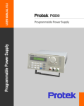
CSI3645A
user’s manual
Chapter 2 Operation.....................................7
2.1 General operation ..................................7
2.2 Function introduction...............................7
2.2.1. Main functions.....................................7
2.2.2 Sub-functions.......................................7
2.3 The operation of the function...................7
2.3.1 V-set....................................................8
2.3.2 I-set......................................................9
2.3.3 Switch ON/OFF power output...............9
2.3.4 Store data function...............................10
2.3.5 Recall data function............................11
2.3.6 The function of the Menu...................12
2.3.6.1 Set up the maximum voltage
output value (0~36V).......................12
2.3.6.2 Set up the key sound......................13
2.3.6.3 Set up the communication...............13
2.3.6.4 Set up communication
address (0~254)..............................13
2.3.6.5 Set up locking key board..................13
2.3.6.6 Set up constant power output..........14
2.3.6.7 Set up save option...........................14
2.3.6.8 Exit function.....................................14
Chapter 3 System Installation...................15
3. 1 System Installation..............................15
3.2.System Start..........................................17
CONTENTS
Caution.........................................................2
Safety notes..................................................2
Chapter 1 General Introduction ...................3
1.1 General Introduction...............................3
1.2 Specification...........................................3
1.3 Features ................................................4
1.4 Dimension and Structure........................4
1.4.1 Dimension............................................4
1.4.2 Structure..............................................5
1.4.2.1 Front view ........................................5
1.4.2.2 Back view..........................................6
CSI3645A Programmable Power Supply
Circuit Specialists, Inc. 2002.3
Chapter 4 The Function Introduction.......18
4.1 Users’ Login.........................................18
4.2 The Definition of the Power Supply......18
4.3 The COM Port and Lower Machine
(Power Supply) Address Set.................19
4.4 Run the Communication........................20
4.5 Stop the Communication.......................20
4.6 Select POWER.....................................21
4.7 Select PC to POWER
Control Instructions...............................21
4.8 Set the Voltage Range..........................21
4.9 Set the Max Current..............................21
4.10 Users’ Manage....................................23
4.11 Query the Report................................24
4.12 Explanation of the Interface
Indicating Components.......................25
4.13 The State Bar.....................................26
4.14 Help....................................................25
4.15 Logout User........................................26
1
CSI3645A-TYPE USER’S MANUAL
CAUTION
SAFETY NOTES
Before switching on the DC Power supply, the protective earth terminal of this instrument must be connected to the protective conductor of the AC line power cord. The
AC line plug shall be inserted only in a socket outlet provided with a ground. The ground may be lost
by use of an extension cord (or power cable) without a protective grounding conductor.
The following general safety precautions must be observed during all phases of
operation, service, and repair of this instrument. Failure to comply with these precautions or with specific warnings elsewhere in this manual violates safety standards of
design, manufacture, and intended use of the instrument. The Manufacturer assumes
no liability for the customer’s failure to comply with these requirements.
Ground the Instrument
This product is provided with a protective earth terminal. To minimize shock hazard,
the instrument chassis and cabinet must be connected to an electrical ground. The
instrument must be connected to the AC power supply mains through a three-conductor power cable, with the third wire firmly connected to an electrical ground (safety
ground) at the power outlet. For instruments designed to be hard-wired to the AC power
lines (supply mains), connect the protective earth terminal to a protective conductor
before any other connection is made. Any interruption of the protective (grounding)
conductor or disconnection of the protective earth terminal will cause a potential shock
hazard that could result in personal injury. If the instrument is to be energized via an
external autotransformer for voltage reduction, be certain that the autotransformer common terminal is connected to the neutral (earthed pole) of the AC power lines (supply
mains).
Keep Away From Live Circuits
Operating personnel must not remove instrument covers. Component replacement
& internal adjustments must be made by qualified service personnel. Do not touch or replace components with power cable connected.
Under certain conditions, dangerous voltages may exist even with the power cable
removed. To avoid injuries, always disconnect power, discharge circuits and remove
external voltage sources before touching components.
Do Not Substitute Parts or Modify Instrument
Because of the danger of introduction additional hazards, do not install substitute
parts or perform any unauthorized modification to the instrument. Return the instrument to a qualified dealer for service and repair to ensure that safety features are
maintained.
CSI3645A Programmable Power Supply
Circuit Specialists, Inc
2
CSI3645A-TYPE USER’S MANUAL
Chapter 1 General Introduction
1.1
General Introduction
CSI3645A-Type programmable DC power supply is designed and manufactured by ARRAY
Electronic Co., Ltd. for Circuit Specialists, Inc. The CSI3645A is a high quality mini-size DC
programmable power supply with a professional appearance. It is equipped with a back-lit
LCD display, numeric keypad & rotary code switch for ease of use. Voltage, current and power
can all be displayed on the LCD or a computer (with optional RS-232 adaptor). It can be operated at
constant current mode, constant voltage mode & constant power mode. Also it can be set to
maximum limits for current & power outputs. It is an essential instrument for scientific
research, education, test labs, or any environment requiring a sophisticated DC power source.
1.2 Specification
Type
3644A
Output
1
3645A
1
3646A
1
Output voltage
0~18V
0~36V
0~72V
Output current
0~6A
0~3A
0~1.5A
Voltage resolution 1mV at 0~3.999V
5mV at 4~18V
1mV at 0~3.999V
1mV at 0~3.999V
10mV at 4~36V
20mV at 4~36v
Current resolution
<=1mA
Ripple
<=3mVpp
Communication
RS232/RS485 *
Monitor software
Free software VC++ / VB / DELPHI / LABVIEW / COM parts
Memory
10 points EEPROM
Protective mode
Over voltage /over current /over power
Power voltage
AC 110/220 available (60/50HZ)
Weight
5.5Kg
Accessories
Software, users manual, AC power cable, handlebars
Purchase
Option Parts
Communication adaptor module for RS232
Mounting rack
CSI3645A Programmable Power Supply
Circuit Specialists, Inc.
2002.3
3
CSI3645A-TYPE USER’S MANUAL
1.3 Features
1. LCD display with back light.
2. Number keypad.
3. High resolution at 1mv.
4. Protection for over or low voltage.
5. Protection for over or low current.
6. Adjustable voltage and constant voltage output.
7. Adjustable current and constant current output.
8. Can be set for maximum current protection.
9. Can be set by number key or rotary code switch.
10. Power shut-down memory function
11. Monitored by PC software (requires optional RS-232 module).
12. Mini-size and light weight.
13. Can be used in series connect and parallel connect modes.
1.4 Dimension and Structure
1.4.1 Dimension
Fig 1 Dimension of CSI3645A Programmable DC power supply
CSI3645A Programmable Power Supply
Circuit Specialists, Inc.
2002.3
4
CSI3645A-TYPE USER’S MANUAL
1.4.2 Structure
1.4.2.1 Front view
Front panel is for users to operate, and
there is one LCD display, one number
keypad and one rotary keypad. Please see
the following picture.
1
2
4
3
Fig2. Front view of CSI3645 DC power supply
1. LCD display
0.00V
0.00A
0.00W
ON
Fig3. LCD Display of CSI3645 power supply
The Left-upper Corner:
Set voltage value.
(Flashing voltage means low-voltage.)
The Left-bottom Conner:
Output power value.
(Flashing power value means over power.)
The Right-upper Conner:
Output current value.
The Right-bottom Conner:
State:
ON(OFF)
represents the output state of the power supply .
PC(KEY)
represents the operation of the keypad or the computer.
2. Arrangement of the Keyboard
Fig4. Keyboard of CSI3645 DC power supply
In common state, the keyboard will execute the prompting functions of the black
words. And in special mode, it will change
into the functions of the orange colored words.
CSI3645A Programmable Power Supply
Circuit Specialists, Inc. 2002.3
0~9: The number keys
Store: Save the current setting value
Recall: Read the saved setting value
Menu: The menu operation key
OUT ON/OFF: Start/Stop the output
Enter: The confirmation key
V-set: The output voltage value set
I-set: The max output current set
: The up moving key
: The down moving key
V/A: Represent V at the voltage mode, represent A at
the current mode.
mV/ mA :Represent mV at the voltage mode, and
represent mA at the current mode
5
CSI3645A-TYPE USER’S MANUAL
3. Rotary code switch and function keys
Left Operation: The left moving key
Right Operation: The right moving key
ESC: Can be used to exit any working state
OK: Confirmation key
Rotary SW: The rotation key
Fig5. Rotary and function keys
1.4.2.2 Back view
PC connection
Wire rack
interface
fan wrap
Power supply plug
Fuse
Change over Switch
Fig 6 Back view
The fuse can be changed easily by using a small screw driver. Please use a fuse within
the range of 2~2.5A.
CSI3645A Programmable Power Supply
Circuit Specialists, Inc. 2002.3
6
CSI3645A-TYPE USER’S MANUAL
Chapter 2 Operation
2.1 General operation
1. Connect the power supply with a PC
Fig 7 Connect the power supply with PC
2.2 Function introduction
2.2.1. Main functions
1. Set up a constant voltage from 0 to 36V
2. Set up a constant current or maximum protection current from 0 to 3A
3. Switch ON/OFF the power supply output
4. Store 10 sets of data which can be set up
5. Recall the stored data
2.2.2 Sub-functions
1. Set up maximum protection voltage
2. Turn ON/OFF the sound of key
3. Set up the communication
4. Lock keyboard ON/OFF
5. Set up the maximum power
6. Save the last set up voltage
2.3 The operation of the function
We know that there are 4 main functions and 6 sub-functions of this power supply, the
following will describe how to operate all of the functions. Before any operation, please connect
the power, and switch the power on. A power -on indicator will light.
CSI3645A Programmable Power Supply
Circuit Specialists, Inc. 2002.3
7
CSI3645A-TYPE USER’S MANUAL
2.3.1 V-set (set up a constant voltage from 0 to 36V)
Setting up a constant DC voltage output is the first main function of programmable DC power
supply. The CSI3645A provides two methods to set up the constant DC voltage output by
using the number keyboard or the rotary button. Please see the following operation procedure.
Procedure
Step 1
Operation details
Press “V-set”
Step 2
Enter the password ( Or jump to step 4 if the keyboard
0.00W ON
ENTER PASSWORD
Step 3
is unlocked)
Press “Enter” button ( it will return to step 2 if your
ENTER PASSWORD
Step 4
password is wrong for reentering)
Press “V-set” to enter the original value which displayed
****
SET VOLT= 24.00V
on the LCD, or enter a new value by using the number
key or rotate “Rotary SW” to adjust the voltage value
Step 5
and then press the “V-set” button for confirmation
Press “V/mV” button to change the voltage unit into mV,
it will return to step 4 for reentering if the current voltage
exceed the high limited value
LCD display
24.00V 0.00A
NEW=
SET VOLT= 24.00V
NEW= 18
It will exit the setting up voltage operation at any procedure by press ESC button
Example: Setting the output voltage at 24.3V
1. Set up by using the number keyboard
Step1. Press “V-set” button,
Step2. Enter the password by using the number keyboard (if the keyboard is unlocked,
please do step 4),
Step3. Press Enter button (if the password is wrong, please do step 2 for reentering),
Step4. Press “2”, “4”, “.” and “3” button to enter the voltage value,
Step5. Press “V-set” button to confirm the voltage value.
2. Set up by using the Rotary SW
(1) If the keyboard is unlocked by password, directly rotate the “Rotary SW” button, and the
voltage will be continually changed from the previews value according the rotation. At the
beginning, the cursor will be shown on the last number of the value which is indicated on the
LCD, you can move the cursor to the first number, second number etc by using “ ”and “
”
buttons, and then rotate to change each number, and let it stay at 24.3 V, then confirm the value
by pressing “V-set” button.
(2) If the keyboard is locked by password
Step1. Press “V-set” button,
Step2. Enter the password by using the number keyboard,
Step3. Press Enter button (if the password is wrong, please do step2 for reentering),
Step4. Rotate the Rotary SW button to change the value, the operation is as the same as above(1)
Step5. Press “V-set” button to confirm the voltage value.
CSI3645A Programmable Power Supply
Circuit Specialists, Inc. 2002.3
8
CSI3645A-TYPE USER’S MANUAL
2.3.2 I-set (set a constant current or a maximum current from 0 to 3A)
CSI3645A power supply can be set for a constant current or a maximum current from 0 to
3A. There are two special applications for users when setting the I-set. Please see the
following example.
Conditions: voltage=24V, load R=12 , then V/R=2 A, it represent that the power supply
provide the load 2A current. If
1)Set up the current I = 2.5A, then the current should be displayed on the screen as 2A.
2)Set up the current I = 1A, then the current should be displayed on the screen as 1A. It means
that the power supply provides load 1A current.
Set up current procedure is as following:
Procedure
Operation details
LCD display
Step 1
Press “I-set”
24.00V 0.00A
0.00W ON
Step 2
Enter the password ( Or jump to step 4 if the
keyboard is unlocked)
ENTER PASSWORD
Step 3
Press “Enter” button ( it will return to step 2 if your
password is wrong, for reentering)
ENTER PASSWORD
****
Step 4
Press “I-set” to enter the original value which displayed
on the LCD, or enter a new value by using the number
SET CURR=0.00A
NEW=1.2
key or rotate “Rotary SW” to adjust the current value
and then press the “I-set” button for confirmation,
Step 5
Press “A/mA” button to change the voltage unit into mV,
it will return to step 4 for reentering if the current
SET CURR=0.00mA
NEW= 15.0
exceed the high limited value of 3A
User may exit the set current operation at any point by pressing the ESC button
2.3.3 Switch ON/OFF power output
The output of CSI3645A should be off when it is powered, users can change
the output status by using ON/OFF button. The button is a turn over button, when the original
output is ON, press the button, then the output will be changed to OFF status, when the original
output is OFF, press the button, then the output will be changed to ON status.
CSI3645A Programmable Power Supply
Circuit Specialists, Inc 2002.3
9
CSI3645A-TYPE USER’S MANUAL
2.3.4 Data store function
This function makes the CSI3645A very easy to use. If you want to use a constant voltage and
current (such as 24V and 2A, or 12V and 2.3A etc) every day, you just need to set up the data for the
first time, and then store the data in the power supply, and then recall it when you need the data
again. CSI3645A can store up to 10 sets of data.
The stored contents include 1) Voltage value; 2) Current value; 3) Maximum voltage; 4)
Locked/unlocked key board; 5) Maximum power ; 6)Baud rate; 7) Communication address.
The data store function is always done after setting up V-set, I-set etc. The operation is as follows:
Procedure
The operation Methods
LCD display
Step 1
Press “Store” button
****V ****W
****A **
Step 2
Enter the password ( Or jump to step 4 if the keyboard
is unlocked)
ENTER PASSWORD
Step 3
Press “Enter” button ( it will return to step 2 if your
password is wrong for re-entering)
Step 4
Enter the set value to store number(from 1 to 10) by
using the number key-pad or rotate the rotary button to
Step 5
change the set value number for storage
Press “Store” button to confirm the set value, if the
ENTER PASSWORD
1234
STORE 1
STORE *
number is out of the range from 1 to 10, it will retune to
Step 2 for re-entry.
You may exit the data store function at any point by pressing the ESC button
For example: To set up the voltage=15V, current=2A, Maximum output voltage=18V, key board
locked, Maximum output power=25W, Baud rate=9600, communication address=05, after doing
the setup , users can store all the above as a set of data, such as the 01 or 02 etc.
CSI3645A Programmable Power Supply
Circuit Specialists, Inc.
2002.3
10
CSI3645A-TYPE USER’S MANUAL
2.3.5 Recall data function
The CSI3645A can store up to 10 sets of data in the power supply memory
Also, any single data set can be easily recalled from the memory. This means that you do not need
to set up again for repetitive requirements. Users can enhance the benefits of the CSI3645A &
recall one set of data from the stored data sets, including set up of 1) Voltage value; 2)
Current value; 3) Maximum voltage; 4) Locked/unlocked key board; 5) Maximum power ; 6)
Baud rate; 7) Communication address.
The recall operation is as follows:
Procedure
The operation Methods
LCD display
Step 1
Press “Recall” button
0.000V 0.00A
0.00W OFF
Step 2
Enter the password ( Or jump to step 4 if the keyboard
is unlocked)
ENTER PASSWORD
Step 3
Press “Enter” button ( it will return to step 2 if your
password is wrong for reentering)
ENTER PASSWORD
1234
Step 4
Enter the number of the set data which you want to recall
(from 1 to 10) by using the number key or rotate the
RECALL 1
Step 5
rotary button to change the number you want recalled.
Press “Recall” button to confirm , if the number is out of
RECALL *
the range from 1 to 10, it will retune to Step 2 for re-entry
You may exit the Recall operation at any point by pressing the ESC button
CSI3645A Programmable Power Supply
Circuit Specialists, Inc. 2002.3
11
CSI3645A-TYPE USER’S MANUAL
2.3.6 The Menu function
The CSI3645A power supply provides a Menu operation for some special functions. The operation
and function are as follows.
Procedure
The operation Methods
LCD display
Step 1
Press “Menu” button
0.000V 0.00A
0.00W OFF
Step 2
Enter the password ( Or jump to step 4 if the keyboard
is unlocked)
ENTER PASSWORD
Step 3
Press “Enter” button ( it will return to step 2 if your
password is wrong for reentering)
ENTER PASSWORD
1234
Step 4
The LCD displays the menu functions one by one. User
can use the UP and DOWN button to select each
MAX OUT VOLTAGE
KEY SOUND SET
function, Press “Enter” button to execute
the selected function
COMMUNICATION SET
ADDRESS SET
KEY LOCK
MAX OUT POWER
SAVE SET
EXIT
You may exit the Menu operation at any point by pressing the ESC button
The menu operation includes MAX OUT VOLTAGE, KEY SOUND SET, COMMUNICATION SET, ADDRESS SET, KEY LOCK, MAX OUT POWER, and Save set function. We will
describe the details as follows.
2.3.6.1 Set up the maximum voltage output value (0~36V)
When you select the MAX OUT VOLTAGE function, the LCD will display as:
MAX VOLT = 24 V
NEW=
You can set the voltage value by using the UP and
DOWN key or rotating the ROTARY button. Then confirm the value by pressing “Enter” button.
2.3.6.2 Set up the key sound
When you select the KEY SOUND SET function, the LCD will display as:
KEY SOUND ON
KEY SOUND OFF
CSI3645A Programmable Power Supply
Circuit Specialists, Inc. 2002.3
Users can select KEY SOUND ON or KEY SOUND
OFF by using UP and DOWN key button. KEY SOUND
ON represent the sound of keys will be on , and KEY
SOUND OFF represent the sound of keys will be off.
12
CSI3645A-TYPE USER’S MANUAL
2.3.6.3 Communication set up
This function is for monitoring the output data of the power supply by using a computer.
When you select COMMUNICATION SET function, the LCD will display as:
BUAD RATE=4800
BUAD RATE=9600
BUAD RATE=19200
BUAD RATE=38400
Users can change the communication setup by using
UP and DOWN keys or rotating the ROTARY button, and
confirm the value by pressing “Enter” button.
BUAD RATE 4800 represent BUAD rate=4800bps
BUAD RATE 9600 represent BUAD rate=9600bps
BUAD RATE 19200 represent BUAD rate=19200bps
BUAD RATE 38400 represent BUAD rate=38400bps
2.3.6.4 Set up communication address (0~254)
This communication address function is for monitoring multi-power supply system. In the
system, one computer can monitor 255 power supplies at the most by the connecting RS232 and
485 bus. So we should give each power supply an address.
When you select ADDRESS SET function, the LCD will display as:
SET ADDRESS =12
NEW=
Users can change the communication address value
by using UP and DOWN keys or rotating the ROTARY
button, and confirm the value by pressing “Enter” button.
The range of the address value is from 0 to 254.
2.3.6.5 Set up locking keyboard
After you locked the keyboard, you must enter the correct password to unlock it, then you can
use the number keys and the ROTARY button. This function is for the safety & security.
When you select the KEY LOCK function, the LCD will display as:
ENTER PASSWORD
CSI3645A Programmable Power Supply
Circuit Specialists, Inc. 2002.3
Users can enter 4 numbers or letters as the password
by pressing the number button or by using ? and ? buttons or ROTARY button to change the number or ASCII
number which will be your password, and confirm the
password by pressing the “Enter” button.
13
CSI3645A-TYPE USER’S MANUAL
2.3.6.6 Set up constant power output (the range is from 0 to 108 W)
When you select the MAX POWER function, the LCD will display as:
MAX POWER=56 W
NEW=
Users can change the power value by using UP and
DOWN keys or rotating the ROTARY button, and confirm the value by pressing the “Enter” button. The range of
the power value is from 0 to 108W.
2.3.6.7 Set up SAVE OPTION
This function is for saving the last set up of the voltage output. It is a convenient & time saving
feature when the same voltage valueis needed repeatedly. It will display the same voltage value
when the power supply is powered up.
When you select the SAVE OPTION function, the LCD will display as:
SAVE VOLTAGE
DON T SAVE VOLT
Users can change the selection by using UP and DOWN
keys or rotating the ROTARY button, and confirm the
selection by pressing “Enter” button. To select SAVE
VOLTAGE means to save the last set up voltage, to select
DON T SAVE VOLT means not to save the last set up
voltage value.
2.3.6.8 EXIT function
When the EXIT function is selected, you will exit the Menu operation.
CSI3645A Programmable Power Supply
Circuit Specialists, Inc. 2002.3
14
CSI3645A-TYPE USER’S MANUAL
Chapter 3 System Installation
3. 1 System Installation
3.1.1 Put the disk into the CDROM drive. Then the system will run automatically and the initial diagram as
in Fig. 3-1 will be displayed.
Fig.3-1 The Installation Initial Interface
3.1.2 Then it will enter the interface as in Fig. 3-2. Press “NEXT” to continue.
Fig. 3-2 The Installation Interface 2
3.1.3 In Fig. 1-3, there is some explanation to some products’ introduction. Read it and press “YES” to
continue. This must be done to continue with the installation.
Fig. 3-3 The Installation Interface 3
3.4 In Fig. 3-4, click “BROWSE” to select installation directory path. The default directory path is “C:
\Program Files\Array\PowerMS”
CSI3645A Programmable Power Supply
Circuit Specialists, Inc. 2002.3
15
CSI3645A-TYPE USER’S MANUAL
Fig. 3-4 The installation Interface 4 The Installation Directory Path Set
3.1.5 In Fig. 3-5, users may select the installation type. Generally, select “TYPICAL” and click “NEXT”
to continue.
Fig. 3-5 The Installation Interface 5
3.6 In Fig. 3-6, enter the file folder’s name and the default name is “POWERMS”. Generally it is not
needed to enter and it is just need to click “NEXT”.
Fig. 3-6 The Installation Interface 6
3.1.7 Click “NEXT” and the installation system will enter the files’ copying state. Please wait patiently for
the end of the files’ copying. Then the PowerMS system installation is finishing.
Fig. 3-7 The Installation Interface 7 The Files’ Copying
CSI3645A Programmable Power Supply
Circuit Specialists, Inc. 2002.3
16
CSI3645A-TYPE USER’S MANUAL
3.2.System Start
3.2.1 In Fig. 3-8, select the file folder of “Start | Program | Array”. And then click the “PowerMS” in the
menu.
Fig. 3-8 The System Start Interface
3.2.2 Enter the initial interface as shown in Fig. 3-9.
Fig. 3-9 The System Start Diagram
3.2.3 Wait for the end of the system initialization and then it will enter the main interface as shown in
Fig. 3-10.
Fig. 3-10 The PowerMS Main Interface
Explanation:
1. Every time the PowerMS system is started, it will automatically be in minimized state. And at this
time the icon
is in the state bar on the desk. Click the right key of the mouse on the icon, the menu
as shown in Fig. 3-11 will be displayed.
Fig. 3-11
CSI3645A Programmable Power Supply
Circuit Specialists, Inc. 2002.3
17
CSI3645A-TYPE USER’S MANUAL
“Show”: Show the interface.
“Hide”: Hide the interface.
“Start Communicate”: Start the communication.
“Stop Communicate”: Stop the communication.
“About PMS”: Show the help contents.
“Exit System”: Close the system. (And users must register before.)
2. If the system is started from the program file folder, it will be at the maximized state.
3. System Uninstallation
It is only need to select “
”in the program file folder. And it must be done after the
closing of the system otherwise there will be no way to uninstall.
Chapter 4
The Function Introduction
4.1 Users’ Login
When the system is first entered, it is set to be in the lowest limit of authority state. At this time, only the COM
port set and the POWER selection can be carried out, and other functions cannot be used. So users must login and
operate and it guarantees the security of the system.
Select the icon
and the interface as shown in Fig. 4-1 will be displayed. After the first time installation,
the system will provide for two users: the “Manager” and the “Lowest” for you to select. Selecting “Manager”,
entering the password “0001” and then clicking “OK”, in this way the system will have all the functions.
Explanation: “Manager” is the user(s) of with management authority; “Lowest” is for user(s) with the lowest limit of authority.
the two user levels are retained by the system.
Fig.4-1 The User Login Interface
4.2 The Definition of the Power Supply
Select the function item
and then the interface as shown in Fig. 4-2 will be displayed.
Fig. 4-2 The Power Definition Interface
CSI3645A Programmable Power Supply
Circuit Specialists, Inc. 2002.3
18
CSI3645A-TYPE USER’S MANUAL
Add: Select “Add” in the function items and then input the contents of each item. After the
set of the input, select “Save” to save it.
Delete: Select the POWER record to be deleted in the table and then select “Delete”. Finally
select “Save” and it will be deleted.
Modify: Select the POWER record to be modified in the table and then select “Modify” to
modify it. After the modification, select “Save” and it will be modified.
Query: Select “Query” and then wait for the name of the power supply to be queried.
Show: Select “Show” and it will show all the records.
Print: Select “Print” and it will print all the current records.
Parameter Explanation
Parametrer
Explanation
Power Name
Current Up
Name Of the Power Supply
The Max Current
Power Up
Voltage Configure
The Max Power
The Max Voltage
Configure
ID
The ID Number
Range
Remarks
0~3A
Must be Input
Must be Input
0~108W
1~36V
Must be Input
Must be Input
No Consideration
Notes:
When selecting the “Add” function item to add POWER, the name and address of the POWER cannot
be repeated. After entering all the information, click “OK” and the dialogue frame as shown in Fig. 4-3 will be
displayed. In Fig.4-3, select “YES” and the system will close and restart.
Fig. 4-3 System Prompt the restart
4.3 The COM Port and Lower Machine (Power Supply) Address Set
Login in the identity of “Manager” and then select the quick icon after the system restarts. The dialogue
frame as shown in Fig.4-4 will be displayed.
Fig. 4-4 COM Port and address set
In Fig. 4-4, select the page key “COM” and select the COM port from the pull-down table. If the COM port does not
exit, the system will prompt the diagram as shown in Fig. 4-5. And the “OK” button and the page key “ADDRESS”
are out of work. And vice versa. (user must be “Manager” status, otherwise the “ADDRESS”
cannot be used.
CSI3645A Programmable Power Supply
Circuit Specialists, Inc. 2002.3
19
CSI3645A-TYPE USER’S MANUAL
Fig. 4-5 COM Port Failure Opening Dialogue Frame
Set Default POWER Address:
The system will automatically be in the networking state after the start according to the default COM port and
the default POWER. It is just needed to enter the address in the “Default POWER” bar.
Set POWER Address:
Login in the identity of the “Manager” and select the existing COM port. Then the “ADDRESS” page key will
be available.
Fig. 4-6 POWER Address Set
In Fig. 4-6, enter the default address (245) of the lower machine and then click “READ”. If testing successfully,
the “NEW ADDRESS” and “WRITE” functions will be available. If testing failure, then the new address of the
power cannot be set and the prompting diagram as shown in Fig. 4-7 will be displayed. This time the communication
cable must be checked.
Fig. 4-7 Communication Failure
Explanation: For the first time installation each POWER must be deployed with but one address so as to
communicate correctly. Set the parameter and select “OK” and it will enter into the common communication. The
default COM port is COM1 and the default POWER address is 1.
4.4 Run the Communication
After the COM port and ADDRESS set, select the button
and the system will start the communication. If the
communication is normal, the prompting information as shown in Fig. 4-8 will be displayed. And if the communication has failed, the prompting information as shown in Fig. 4-9 will be displayed.
Fig. 4-8 Normal Communication
Fig.4-9 Failed Communication
4.5 Stop the Communication
Select the button
and the system will stop communication.
CSI3645A Programmable Power Supply
Circuit Specialists, Inc. 2002.3
20
CSI3645A-TYPE USER’S MANUAL
4.6 Select POWER
In Fig. 4-10, select the POWER name from the listing frame and it will be set.
Fig. 4-10 Selecting the POWER
4.7 Select PC to POWER Control Instructions
1.) Methods 1
As in Fig. 4-11, there are four control instructions in total.
CLOSE POWER
OPEN POWER
PC CONTROL
POWER SELF
Fig. 4-11-1 Select the Control Instruction
Explanation: The system default control instruction is the PC CONTROL state. And when the system is
closed or the POWER is switching, the system will automatically set to POWER SELF state.
2.) Methods 2
POWER ON/OFF Set
POWER Control Set
Fig. 4-11-2 Selecting Control Instruction
4.8 Set the Voltage Range
There are two methods to set the voltage range: one is by using the rotary button (1~36) and the other is by
using the keyboard (0.004~36.000). If you want to set accurately, please use the keyboard. In general state, you
can use the rotary button.
Fig. 4-12 Using the Rotary Button
Fig. 4-13 Using the Keyboard
1) Using the rotary button: Move the mouse to the icon and then rotate the button.
2) Using the keyboard: Select the “V” button, enter the data and then select the “OK” button.
4.9 Set the Max Current
There are two methods to set the voltage range: one is by using the rotary button (1~36) and the other is by
using the keyboard (0.004~36.000). If you want to set accurately, please use the keyboard. In general state, you
can use the rotary button.
CSI3645A Programmable Power Supply
Circuit Specialists, Inc. 2002.3
21
CSI3645A-TYPE USER’S MANUAL
Fig. 4-14
1) Using the rotary button: Move the mouse to the icon
Fig. 4-15
and then rotate the button.
2) Using the keyboard: Select the “A” button, enter the data and then select the “OK” button.
Note: Authority above “General” must be used for this setting.
4.10 Users’ Manage
For the security of the system, the manager must set a login user name and a password for each operator. (This
can only be done by the manager.)
Select the button
and the interface as shown in Fig. 4-16 will be displayed.
Fig. 4-16 Users Manage
1.) Append User
Select the page key “APPEND” and the user type (generally is “General”). Enter the user’s name (cannot be
blank) and the password twice (must be the same) and then click “OK”.
Explanation: “General” is the general user; “Lowest” is the user of the lowest limit of authority.
2.) Modify the User’s Name and Password
In Fig. 4-17, select the user name and enter the password. Then enter a new user name (cannot be blank)
and a new password twice (must be the same). After entering, press “OK”.
Fig. 4-17 Modify the Password and the Name
Explanation: The user “Lowest” is retained by the system and cannot be modified.
3.) Query User(s)
Select the page key “USER(S)”, the dialogue frame as shown in Fig. 4-18 will be displayed.
CSI3645A Programmable Power Supply
Circuit Specialists, Inc. 2002.3
22
CSI3645A-TYPE USER’S MANUAL
Fig. 4-18 Query the User(s)
If you want to delete a user, select the user from the listing table and click “Delete”. Then the confirmation
dialogue frame will be displayed for you to confirm. In Fig. 4-19, if you select “YES”, the user will be deleted. And
if you select “NO”, the deletion will be cancelled.
Fig. 4-19 Deleting User Prompting
Note: “Manager” and “Lowest” are retained by the system and cannot be deleted.
4.) Event
Select the page key “EVENT” and the dialogue as shown in Fig. 4-20 will be displayed. It is mainly used to query
the users’ login and logout times so as to manage conveniently. If you want clear records, select “CLEAR” and
“YES” in the prompting confirmation dialogue frame.
Fig. 4-20 Clearing Data Prompting
Fig. 4-21 User Operating Information
Click the right key of the mouse and query according to the users’ name or date. And the following dialogue
will be displayed.
CSI3645A Programmable Power Supply
Circuit Specialists, Inc. 2002.3
23
CSI3645A-TYPE USER’S MANUAL
Fig. 4-22
Query – Name: Query according to the user’s name.
Query – Date: Query according to the date.
Name and Date: Query according to the name and date.
Show all: Show all the information about the users.
4.11 Query the Report
Select the button
and the diagram as shown in Fig. 4-23 will be displayed.
Fig. 4-23 Query the Report
1.) Set the Query Conditions: Set the parameters in the “Query” frame.
2.) Query: After setting the conditions, select “SEARCH” button and all the records agreed with the conditions
will be listed.
3.) Set the Report: Select “REPORT’ and it will be OK.
4.) Print the Report: Select “PRINT” and it will be OK.
5.) Query Totally: Select “TOTAL” and it will be OK. The date range must be selected and the other conditions
cannot be selected. Its main function is to analyze several POWER so as to list the POWER that overflow the
most data. The overflowing data includes the voltage overflowing, the current overflowing and the power
overflowing.
6.) Delete the History Record: Select “DELETE” and the diagram as shown in Fig. 4-24 will be displayed. If
you confirm to delete, select “YES” and it will be OK.
Fig. 4-24 Delete the History Data
CSI3645A Programmable Power Supply
Circuit Specialists, Inc. 2002.3
24
CSI3645A-TYPE USER’S MANUAL
Explanation: The date range condition must be set.
7.) Close: Select “CLOSE” and return to the upper-interface.
4.12 Explanation of the Interface Indicating Components
1.) Instrument Part
The Voltage Value
Voltage Set Value
(Accuracy rate: 5 digits)
(Accuracy rate: 2 digits)
Common Data: Green
Overflowing Data: Red
Fig. 4-25 Instrument Indication
Common Date and Overflowing Data are both in the normal communication state.
2.) Running Curve: Indicates the data acquired at the nearest 10 ports.
4.13 The State Bar
The Voltage Running Diagram
The Current Running Diagram
3.) Keyboard Explanation
Number Keys: 0-9
“C”: the clearing key
“.”: the point key
“
”: the backspace key
“V”: the voltage setting key (Unit: V 0~36.000)
“A”: the current setting key (Unit: A 0~3.000)
“mV”: the voltage setting key (Unit: mV 0~36000)
“mA”: the current setting key (Unit: mA 0~3000)
“Vmax”: input the max voltage value (36V)
“Amax”: input the max current value (3A)
Fig. 4-26
Keyboard Explanation
“OK”: the confirmation key
Panel Part:
V: presents the current voltage set state (Unit: V).
Max 36: presents that the max set voltage value is 36.
0: the current set value
4.14 Help
Power: p3: presents the current selected POWER.
CSI3645A Programmable Power Supply
Circuit Specialists, Inc. 2002.3
25
CSI3645A-TYPE USER’S MANUAL
Add: 3: presents the POWER address.
V: 36: presents the defined voltage max value.
A: 3: presents the defined current max value.
W: 108: presents the defined power max value.
Sending: presents the operation state.
4.15 Logout User
Click the icon
and the help diagram as shown in Fig. 3-26 will be displayed.
Fig. 4-27 Help Interface
Select the icon
and the system will automatically be in the lowest limit of authority. User must login again
for the operation. When leaving, the user must carry out the canceling operation, especially the manager.
4.16 Power Supply State Indication
1. Overloading current indication:
Blue presents normal.
Red presents overloading.
2. Overloading power indication:
Blue presents normal.
Red presents overloading.
3. Power supply ON/OFF state
Blue presents OFF.
Red presents ON.
4.Power supply control type:
Blue presents CONROL SELF.
Red presents PC CONTROL.
4.17 Exit the System
Select the icon
. To do this, you must login first, otherwise the system cannot be closed.
CSI3645A Programmable Power Supply
Circuit Specialists, Inc. 2002.3
26