1
Commodore Free Magazine
www.commodorefree.com
COMMODORE SCENE VGA UPDATE
COMMODORE FREE
Ok everyone has done it before and been using it for years, problem is if you
use it with anything like GEOS or WHEELS you know the A22 board does have
some problems, in an attempt to get perfection from the device Allan from
www.commodorescene.org.uk has been working on the board and some other
options I have included some off his emails about the unit .
TO : Commodore Computer club
FROM : COMMODORE SCENE
SUBJECT VGA UPDATE
I'm busy tomorrow but this afternoon I'm going to set up the existing adaptor
test platform and remind myself how it all works, then on Wednesday I'm going to build several units (hopefully boxed) and send them to you both for testing later this week :-)
Make sure you guys have access to an LCD with svideo, preferably more than
one
;-)
Meeting up, I'm okay for a meet up later this month but I just have to make
sure I'm not working or on kid duty !
Hi Guys,
I finally have some time to myself. I spent all yesterday trying to simplify the
C=VGA into a single cable (RGBI>SVGA), unfortunately schematics for the
RGBI>SCART cable do not work on the SVGA socket so that has been shelved
for now.
All the Best, Allan
RGBI>SCART = Already several schematics available, more testing later to produce a good quality output.
RGBI>SVGA = Not feasible yet, more testing late - I WANT this one ;-)
RGBI>SVIDEO = Working, prototype units later this week.
RGBI>Composite = Not viable as the output signal quality is very poor.
As most LCD panels can be bought with SVGA & SVIDEO I think the best thing is
to concentrate on the SVIDEO adaptor we already have as this seems to be the
most workable and adaptable. Despite my best attempts I can't get the output
100% correct but the current configuration is pretty close so I'm going to build
a couple (from Nigel's) and tidy it up a bit so it looks nice. If its okay with you
Nigel I will send one to you and one to Shaun. That leaves me with my two, the
one I butchered for the test rig will stay that way for future testing and the
other one I will try to make look like a finished project.
TO : Commodore Computer club
FROM : COMMODORE SCENE
SUBJECT VGA UPDATE
Hi Guys,
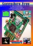
As you can see from the pictures the unit is nearing completion.
This first unit is not quite right as some of the holes are out of alignment, your
units should be okay :-)
At the moment there are a couple of small hold ups,
(1) my local Maplins didn't have the required variable resistors so I've had to
order them,
(2) Maplins also only had one enclosure (jeez they're useless), again I've had to
order some.
Other differences to the pictures supplied, providing the variable resistors actually work, the unit will have a total of six adjustment screws ! On the top of
the unit will be R G B (on the A22 board) - these should not need altering as I
will set these up for optimum gain. Probably on the right hand side will be
three further adjusters for the intensity of the three colours Ri Gi Bi - this is the
bit that most people will need to alter, again, I will set the units up to function
on my monitor but they may need adjusting to suit different LCD panels.
Let me know if you don't have an SVIDEO (male to male) cable or the 9 pin
(male to female) cable and I will make sure your unit comes with one/both.
Also, make sure you have a 9v DC power supply (I use the CS-SuperPSU). The
A22 board can use anything from 9~12v but I have been using it at 9v without
any problems.
I'll do what I can but until the parts arrive I can't finish the units off. Good news
though, I have Monday, Tuesday and Wednesday to myself next week again :-)
All the Best, Allan
TO : Commodore Computer club
FROM : COMMODORE SCENE
SUBJECT VGA UPDATE
Nigel : you'd better hold the front page on a future issue of CF, we can do an
interim report on the testing rig version if you want ?
Its only taken me the best part of 9 years to accomplish!
Hi Guys,
I can't tell you how excited I am right now !
Right, I'm going to have a sit down and calm down before I build two finished
units for you guys. I've been at this for the last 5 hours and I'm tired out.
Just take a look at the attached shots, these are the C128 in 80 column mode
in Wheels128. Everything is there - the desktop background, the cursor are
now visible even on the washed out background, all the shading is correct and
even the colours are 99% correct (I'll work on the other 1% later).
All the Best, Allan
After all the messing about with the LCD monitor settings over the years I forgot to reset them, when I did it all came back into focus and a bit of fine tuning the monitors colour & contrast brought it to life.
You'll have to excuse the poor photography and take my word for it that they
are crisp and clear. The last picture shows the final combination of resistors
and diodes. Please feel free to report on this if you wish to and you can use the
pictures if you like. Once I get the building procedure correct I'll do a step by
step article so anyone can make one, although it will be a bit fiddly.
Page 16