1
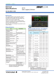
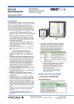
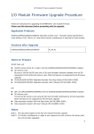
Data Acquisition & Control
Bulletin 04L51B01-01EN
www.smartdacplus.com
Data Acquisition & Control
Your business environment is complex and fast changing. You need
smart and powerful systems that can adapt to your process.
is a fresh approach to data acquisition and control,
with smart and simple touch operation as a design priority.
Measure, display and archive process data with greater
levels of clarity, intelligence and accessibility.
The
concept begins with the
all-new GX/GP, an integrated I/O and recording
system with a familiar touch operator interface.
Highly adaptable, very capable and easy
to operate is the new GX/GP.
Now that's SMART.
Smart
User Interface
Provides a smooth, familiar user
experience
Smart
Architecture
Enables a scalable data acquisition
system
Smart
Functionality
Offers a seamless data transfer
environment
Ethernet
Observe
Variety of display functions
Powerful data search functions
Status indicator lamp functions
Interact
Touch screen for intuitive operation
Easy-to-navigate, user-oriented design
Supports freehand messages
Adapt
Record
Add I/O modules when you need more channels
Low temperature operation
Locking front panel for media security
Measure
Direct output to printers
Convenient report creation function
Viewer software for data analysis
Connect
Wide-ranging input/output specifications
Multichannel I/O
Easy-to-read screens
Browser-based real time monitoring
Centralized data management via FTP server
Powerful networking functions
Paperless recorders
(panel-mount type)
Paperless recorders
(portable type)
Input/output modules
STANDARD software
Smart User Interface
An intuitive UI engineered for ease-of-use
Seamless display of historical trends
Past
Present
Flick or drag even during measurement to scroll data
for seamless display of historical trends.
The touch screen works even when you are
wearing gloves.
Flick
Zoom in or out on the time axis
Pinch apart / Pinch together
Pinch together : Zooms out on the time axis
Pinch apart : Zooms in on the time axis
Change the position of digital values
All historical trends can be displayed in one screen.
Move the scale to view details
Easy operation with shortcuts
Drag
[Patent pending]
Drag the scale to display corresponding digital values.
You can insert your own BMP images to customize the
scale.
Powerful search functions
Easily find data using various displays including calendars and summary screens.
Search from a calendar
Search from a variety of summary screens
Drag
You can drag the digital display section up, down, left,
or right to change its position.
Historical trend screen
4
Summary screens can be sorted by
item for faster searching.
Display the menu at the push of a button
Simply push the front panel MENU
key once to display the menu
screen. The menu screen gives you
access to a variety of functions. The
MENU key is backlit by a color LED
that indicates operating and alarm
status.
Connect a mouse and keyboard for a "PC feel"
With the USB interface option, you can connect a keyboard and/or mouse
to control on-screen operations (text input, etc.). And with USB memory,
you can save data and easily transfer it to a PC.
Blue :Running
(no alarms)
Red :Alarm occurring
Not lit :Power off
Move the scale, and when you want to
check waveform details, it's best to use the
mouse for finger control.
Write freehand messages
You can draw or hand-write on the waveform area using a stylus (included) or
the tip of your finger. You can even select a color and line width.
User interface designed for real people
Human factor led design concepts guided us in everything from screen colors
and button sizes to navigation between screens—the result is an intuitive and
easy user experience. The menu screen is translucent, so you can even keep
your eye on your data while entering settings.
Monitor multiple screens at once
on the multi-panel display
You can divide the display into 2 to 6 sections and assign each to your choice of
screen. You can select from 9 forms (of 2 to 6 screens each), and save up to 20
multi-panel configurations.
Multi-panel display
The multi-panel display is supported only by the GX20/GP20.
5
Smart Architecture
Highly flexible and scalable architecture
GX20
GP20
Handle
LCD screen
Displays operating screens such as
trend graphs, and setting screens.
Operation panel
The START/STOP key can be used
when the operation panel is closed.
MENU key
Simply press the MENU key to display a
menu for access to a variety of screens.
Front panel door lock mechanism
START/STOP key
With front panel door open
Starts and stops recording.
Stylus
Feet
For writing freehand messages.
USB port [Option]
Supports USB 2.0.
SD memory card slot
SD memory card (up to 32 GB)
(format: FAT32 or FAT16), 1 GB included
Easy-to-read display
Power switch
The main unit power switch.
GX20/GP20:12.1" TFT color LCD, 800 x 600 dots
GX10/GP10:5.7" TFT color LCD, 640 x 480 dots
Input/output module slots
For connecting input/output signal wires
from the device under test. For connecting
input/output signal wires for hardware
options.
GX10
Power inlet
(GP10/GP20)
Power and protective ground
Serial communications port
Terminal for RS-422/485 or
RS-232 communications.
USB port [Option]
Supports USB 2.0.
Ethernet Port
A 10Base-T/100Base-TX port.
FAIL output terminal
VGA output connector
[Option]
External monitor connector.
6
[Option]
[Option]
GP10
Modular construction for expandable input/output
Select from a wide variety of input /output modules. The I/O terminals are detachable and come in M3 screw and clamp-terminal types.
The highly flexible design allows you to add or remove modules at any time in the future.
* The GX90YD is only available with M3 screw type terminals.
Your choice of input/output
GX90XA analog input module: DC voltage, thermocouple, RTD, contact input
GX90XD digital input module: Remote control, and more (open collector / non-voltage contact input)
GX90YD digital output module: Alarms, and more (relay, c contact input)
Multichannel measurement and recording
Supports up to 100 channels of input.
Heat dissipating construction
The GX/GP was built for heat dissipation to ensure an even temperature
distribution between module terminals.
Up to 100 channels
GX20/GP20
Heat analysis result
Up to 30 channels
GX10/GP10
Front side
Portable models (GP10/GP20)
Our portable models are easy to take anywhere, and offer the same
functionality and ease-of-use.
Highly secure
The front panel door can be locked to prevent mishandling of the power
switch or external media.
7
Smart Functionality
A full range of network functions and software
Web applications seamlessly connect the GX/GP and PC systems
Through a Web browser (Internet Explorer *) you can monitor the GX/GP in real time and change settings.
You can easily build a seamless, low-cost remote monitoring system with no additional software.
Real time monitoring screen (trend)
Just as on the GX/GP main unit itself, the Web browser lets you
divide the display for monitoring on multiple screens, and even
create and save your own monitor screens as "Favorites."
With the scroll bar, you can seamlessly scroll between past
and current trends. When the sampling interval is 1 second,
the instrument displays 1 hour's worth of historical trends.
Setting screen (AI channel)
The setting screen is highly Excel-friendly, allowing AI channel settings and other information
to be copied to Excel for editing and subsequent re-importing into the setting screen.
Excel
Standard software
Universal viewer
Offline setting software
Data files—whether saved on the GX/GP or transferred via FTP or other protocol to a server—can be
opened by the viewer for display or printing. For specified data, you can perform statistical computation
over an area and export to ASCII, Excel, or other formats.
Enter various settings on a PC, then save the settings to
hard disk or transfer them to the GX/GP. Because you
use a Web browser, it's just like using any other Web
application.
Data converted to an ASCII file
Supported OS *
Software available on the Web!
Download the latest version of the software from the
following URL:www.smartdacplus.com/software/en/
* For Internet Explorer version and supported OS, see the General Specifications (GS 04L51B01-01EN and GS 04L52B01-01EN).
8
Report* and printer output functions
Printer output function
Report creation function
Excel spreadsheet template function
You can print out reports and snapshots directly
from the GX/GP without going through a PC.
For each type of report, you can
output to a PDF file according to
specifiable formats.
Reports can be created automatically using a
spreadsheet template created in Excel.
Excel compatibility means greatly reduced time and
effort spent on reporting.
Ethernet
Template
file
Auto-creation
Printer supporting
the HP-PCL5 language.
Excel spreadsheet
*Mathematical function option is required.
Main networking functions
FTP-based file transfer
FTP client function
Modbus/TCP (Ethernet connection)
FTP server function
Modbus client
The data of server units can be displayed and saved
on the GX/GP using the Modbus/TCP function*.
FTP client
* Communication function option is required.
Ethernet
Display data files
Event data files
Report files
Screenshot
(snapshot) files
On storage media:
Display data files
Event data files
Report files...etc.
Primary Secondary
FTP server
Ethernet
Ethernet
FTP server
The FTP client/server functions allow you to easily share
and manage data from a centralized file server.
GP10
GX10
MW100
FA-M3V
(Up to 16 servers can be connected.)
Modbus RTU (RS-422A/485 connection)
Modbus master
The following network functions are also supported
The data of slave units can be displayed and saved on
the GX/GP using the Modbus RTU function*.
* Communication function option is required.
E-mail sending
Time synchronization (SNTP)
Automated network settings (DHCP)
RS-422A/485
UTAdvanced series controller
Power monitor etc.
(Up to 16 slaves can be connected.)
9
Reliable and durable
Highly secure with proven reliability
Data redundancy
Selectable data saving format (binary or text)
Data redundancy through the internal memory and external storage media.
Measured
data
Data file
A
Data file
Data file
Auto save
B
Data file
Copy
C
Internal memory
A
Data file
B
For increased security, measured data can be
saved in binary format. This format is very
difficult to decipher or modify in traditional text
editors or other programs. To enable easy and
direct opening of the data in text editors or
spreadsheet programs, choose text format.
This allows you to work with your measurement
data without dedicated software.
Data file
C
External memory (SD card)
Measured and calculated data is continuously saved to secure, internal
non-volatile flash memory. At manual or scheduled intervals, the files in
memory are copied to the removable media, which is also secure flash
memory. In addition, the files can be copied and archived to an FTP server.
Because of the inherent reliability and security of flash memory and the storage
methods used, the possibility of losing data under any operating condition or
power failure event is extremely small. When FTP transfer functions are used,
three copies of the same data file can exist at the same time in three locations,
thus providing a high level of redundancy.
Dust and splashproof front panel
(Complies with IEC529-IP65 and NEMA No. 250 TYPE 4*)
High capacity internal memory
Even longer recording durations, and multichannel recording.
Display data file sample time
Internal Memory
Display update (minute/div)
Sampling period (s)
Total sample time
Event data file sample time
Internal Memory
Sampling period (s)
Total sample time
With its IEC529-IP65 compliant front panel,
the GX is ready for use in harsh environments.
Measurement CH = 30 channels. Math CH = 0 channels.
500 MB
30 minutes
60 s
Approx. 2.5 years
Measurement CH = 30 channels. Math CH = 0 channels.
500 MB
1s
Approx. 1 months
Standards supported
* Except the external icing test
UL61010-1, UL61010-2-030(CSA NRTL/C)
Splash-proofing without compromising display quality
The protective sheets on the touch panel display have a special coating on the
front and back to prevent damage from scratches, chemicals, and solvents
while maintaining a high display clarity and resistance to light interference.
* Visual clarity is enhanced by suppression of the concentric circles
that can appear due to light interference.
Touch panel
Composition of the splashproof sheets
Touch-panel side
Spl
High luster AGHC
ash
p
she roof
et
(Anti Glare Hard Coat)
PET
Clear HC
(Hard Coat)
Outer side
10
Two-point touch screen technology
Traditional resistive touch screens can detect only one touch point. The built in
controller and algorithm of the GX/GP can detect two touch points, allowing
intuitive pan and zoom functions during trend monitoring—a first among
paperless recorders.
Controller
MAIN SPECIFICATIONS
For detailed specifications, see the General Specifications (GS 04L51B01-01 EN, and GS 04L52B01-01 EN)
Model
Construction
Panel thickness
GX20
GP20
GX10
GP10
Vertical panel mount
Portable
Vertical panel mount
Portable
2 to 26 mm
2 to 26 mm
Display
12.1" TFT color LCD (800 x 600 dots)
5.7" TFT color LCD (640 x 480 dots)
Touch screen
4 wire resistive touch screen, 2-point touch detection
Max. no. of connectable modules
10 (max. no. of measurement channels:100)
3 (max. no. of measurement channels:30)
* The maximum number of connectable modules is limited by the maximum number of I/O channels, and differs depending on the types and combinations of modules.
No. of mathematical channels
100
No. of communication channels
300
50
500 MB (media: flash memory)
SD memory card (up to 32 GB) (format: FAT32 or FAT16), 1 GB included
USB interface (/UH option): USB 2.0 compliant (external storage media: USB flash memory) (Keyboard/mouse: HID Class Ver. 1.1 compliant)
Internal memory
External storage media
Communication functions
50
Ethernet (10BASE-T/100BASE-TX), IEEE802.3 compliant (Ethernet frame type: DIX)
Connecting configuration: Cascade max. 4 level (10BASE-T), max. 2 level (100BASE-TX), segment length: Max. 100 m
E-mail inform function (E-mail client), FTP client function, FTP server function, Web server function, SNTP client function, SNTP server function, DHCP client function
Modbus/TCP (client*/server functions) */MC option is required.
Options
Serial communications (/C2: RS-232, /C3: RS-422 or RS-485)
Modbus/RTU (master/slave functions)
Other functions
Security functions: Key lock function, login function
Clock functions: With calendar function, accuracy: ±5 ppm (0 to 50°C)
LCD saver function
Rated supply voltage
100 to 240 VAC (allowable power supply voltage range: 90 to 132 VAC, 180 to 240 VAC)
Rated supply frequency
Power consumption
50/60 Hz
Max. 85 VA (100 VAC), max. 110 VA (240 VAC)
Insulation resistance
Between the Ethernet, RS-422/485, and each insulation terminal and earth: 20 M
Between the power terminal and earth: 3000 V AC (50/60 Hz) for one minute
Withstand voltage
External dimensions Main Unit
(W x H x D)
Including modules
Weight (main unit only)
Max. 45 VA (100 VAC), max. 60 VA (240 VAC)
or greater (at 500 VDC)
288 x 288 x 169 (mm)
288 x 318 x 197 (mm)
144 x 144 x 174 (mm)
144 x 168 x 197 (mm)
288 x 288 x 220 (mm)
Approx. 6.2 kg
288 x 318 x 248 (mm)
Approx. 5.7 kg
144 x 144 x 225 (mm)
Approx. 2.1 kg
144 x 168 x 248 (mm)
Approx. 1.9 kg
Analog input module (Universal input module)
Model
GX90XA
Input type
(Inputs: 10)
DC voltage, standard signal, thermocouple, RTD *1, DI (voltage contact), DC current (with external shunt resistor connected)
DCV
20 mV, 60 mV, 200 mV, 1 V, 2 V, 6 V, 20 V, 50 V
Standard signal
0.4-2 V, 1-5 V
RTD Pt100, JPt100, Cu10 GE, Cu10 L&N, Cu10 WEED, Cu10 BAILEY, Cu10 (20°C) =0.00392,
Cu10 (20°C)
=0.00393, Cu25 (0°C)
Thermocouple
R, S, B, K, E, J, T, N, W, L, U, W97Re3-W75Re25,
KpvsAu7Fe, Platinel 2, PR20-40, NiNiMo,
DI
W/WRe26, N (AWG14), XK GOST
Cu100 (0°C)
=0.00425, J263B, Ni100 (SAMA), Ni100 (DIN), Ni120, Pt25, Pt50,
=0.00425, Cu53 (0°C)
=0.00426035,
Pt200 WEED, Cu10 GOST, Cu50 GOST, Cu100 GOST, Pt46 GOST, Pt100 GOST
Level, Contact
Scan intervals
100 *1 /200 *1 /500 ms *1, 1/2/5 s
Power supply and consumption
Insulation resistance
Supplied from main unit, power consumption: 0.7 W or less
Between input circuits and internal circuitry: 20 M or greater (at 500 V DC)
Withstand voltage
Between the input circuits and the internal circuitry:3000 V AC for one minute;between analog input channels:1000 V AC for one minute (excluding b terminals)
Terminal types
M3 screw terminals or clamp terminals (The type suffix code -T1 is not specified.)
Weight
Approx. 0.3 kg
*1 Cannot be set for the electromagnetic relay scanner type (type suffix code: -T1).
Digital input module
Digital output module
Model
GX90XD
Model
GX90YD
Input types
(inputs: 16)
Open collector or non-voltage contact
Output types (outputs: 6)
Relay contact (c contact)
Open collector:
Voltage of 0.5 V DC or less when ON, current of 0.5 mA
or less when OFF
Non-voltage contact:
Resistance of 200 or less when ON, 50 k when OFF
Rated load voltage
Power supply and consumption
100 to 240 V AC or 5 to 24 V DC
264 VAC or 26.4 VDC, 3A/point (resistance load)
Supplied from main unit, power consumption: 1.4 W or less
Insulation resistance
Between output terminals and internal circuitry:
ON/OFF
detection
Contact rating
Max. load voltage/current
20 M
(at 500 VDC)
Power supply and consumption
12 V DC, 20 mA or more
Supplied from main unit, power consumption:0.7 W or less
Insulation resistance
Between input terminals and internal circuitry:20 M
Withstand voltage
Between input terminals and internal circuitry:1500 V AC for one minute
Terminal types
M3 screw terminals
Terminal types
M3 screw terminals or clamp terminals
Weight
Approx. 0.3 kg
Weight
Approx. 0.3 kg
Withstand voltage
Between output terminals and internal circuitry:
3000 V AC for one minute
or greater (at 500 V DC)
External dimensions
Unit: mm
GX10
GX20
288 (11.34)
144 (5.67)
225 (8.86)
174 (6.85) *2
220 (8.66) *1
169 (6.65) *2
*1
*1 With module, *2 Without modules
GP20
144 (5.67)
288
(11.34)
28 (1.10)
288 (11.34)
318
(12.52)
168
(6.61)
144
(5.67)
23 (0.91)
GP10
(approx : inch)
197 (7.76) *2
248 (9.76)
When panel-mounting the GX10/GX20, use two panel mounting brackets. Locate the brackets on the top and bottom, or left and right.
For detailed dimensions and panel cutouts, please see the General Specifications (GS 04L51B01-01EN).
*1
197 (7.76) *2
248 (9.76)
*1
11
MODEL AND SUFFIX CODES
GX10/GX20 MODEL AND SUFFIX CODES
Model
Suffix Optional
Code
code
GX10
Suffix Code
Paperless recorder (Panel mount type, Large display)
GP20
Standard
Type
English, degF, DST (summer/winter time) *9
Display language
/C2
RS-232 *1
Power supply
/C3
RS-422/485 *1
Power cord
/D5
E
Optional features
Model
GP10
-1
Display language
Description
Paperless recorder (Panel mount type, Small display)
GX20
Type
GP10/GP20 MODEL AND SUFFIX CODES
Optional
code
Paperless recorder (Portable type, Large display)
-1
Standard
E
English, degF, DST (summer/winter time) *9
1
100 V AC, 240 V AC
D
Power cord UL/CSA standard
VGA output *2
F
Power cord VDE standard
/FL
Fail output, 1 point
R
Power cord AS standard
/MT
Mathematical function (with report function)
Q
Power cord BS standard
/MC
Communication channel function
H
Power cord GB standard*
/P1
24 V DC/AC power supply
N
/UH
USB interface (Host 2 ports)
Power cord NBR standard
Optional features
Analog input module, Digital I/O module:When the built-in module
Please add the following suffix codes to the main unit model and specification codes.
GX[]0-1-[]/[][]
GP[]0-1-[]1[]/[][]
Description
Paperless recorder (Portable type, Small display)
Optional
code
Description
/C2
RS-232 *1
/C3
RS-422/485 *1
/D5
VGA output *2
/FL
Fail output, 1 point
/MT
Mathematical function (with report function)
/MC
Communication channel function
/UH
USB interface (Host 2 ports)
Optional features
/UC10
With analog input module, 10 ch (Clamp terminal)
(Analog input) *3 *10
/UC20
With analog input module, 20 ch (Clamp terminal) *6
/UC30
With analog input module, 30 ch (Clamp terminal) *7
Analog input module, Digital I/O module:When the individual modules
/UC40
With analog input module, 40 ch (Clamp terminal) *4
MODEL and SUFFIX Code (GX90XA)
/UC50
With analog input module, 50 ch (Clamp terminal) *4
/US10
With analog input module, 10 ch (M3 screw terminal)
/US20
With analog input module, 20 ch (M3 screw terminal) *6
/US30
With analog input module, 30 ch (M3 screw terminal) *7
/US40
With analog input module, 40 ch (M3 screw terminal) *4
/US50
With analog input module, 50 ch (M3 screw terminal) *4
Optional features
/CR01
With digital I/O module, (Output:0, Input:16) *7 *8
(Digital I/O) *3
/CR10
With digital I/O module, (Output:6, Input:0) *7
/CR11
With digital I/O module, (Output:6, Input:16) *6 *7 *8
/CR20
With digital I/O module, (Output:12, Input:0) *5
/CR21
With digital I/O module, (Output:12, Input:16) *5 *8
/CR40
With digital I/O module, (Output:24, Input:0) *5
/CR41
With digital I/O module, (Output:24, Input:16) *5 *8
Model
Description
Suffix Code
Analog Input Module for GX/GP series
GX90XA
10 channels
Number of channels -10
Type
Universal, Solid state relay scanner type (3-wire RTD b-terminal common)
-U2
DCV/TC/DI, Electromagnetic relay scanner type (Isolated between channels)
-T1
Always N
N
-
-3
Terminal form
Screw terminal (M3)
-C
Area
Clamp terminal *
N
MODEL and SUFFIX Code (GX90XD)
Model
Description
Suffix Code
Digital Input Module for GX/GP series
GX90XD
/C2 and /C3 cannot be specified together.
/D5 can be specified only for the GX20 or GP20.
Only one option can be specified.
/UC40, /UC50, /US40 and /US50 cannot be specified for the GX10 or GP10.
/CR20, /CR21, /CR40 and /CR41 cannot be specified for the GX10 or GP10.
If /UC20 or /US20 is specified, /CR11 cannot be specified for the GX10 or GP10.
If /UC30 or /US30 is specified, /CR01, /CR10 and /CR11 cannot be specified for the GX10 or GP10.
A digital input module has M3 screw terminals.
The Display language is selectable from English, German, French, Russian, Korean, Chinese, Japanese. (As of Mar., 2013)
To confirm the current available languages, please visit the following website.
URL: http://www.yokogawa.com/ns/language/
*10 Solid state relay scanner type (type suffix code: -U2). If you need the electromagnetic relay scanner type,
purchase it separately.
*1
*2
*3
*4
*5
*6
*7
*8
*9
16 channels
Number of channels -16
Type
Open collector/Non-voltage, contact (shared common), Rated 5 VDC
-11
-
Always N
N
-3
Terminal form
Screw terminal (M3)
-C
Clamp terminal
N
Area
Model
Description
Suffix Code
Digital Output Module for GX/GP series
GX90YD
Type
Terminal form
6 channels
Product
Mounting bracket (GX10 or GX20)
SD memory card (1GB)
Stylus
Tag sheet
Sheet (paper)
Power cord (GP10 or GP20)
Qty
2
1
1
1
1
1
Product
SD memory card (1GB)
Shunt resistor for screw terminal (M3) (10 Ω ± 0.1%)
Shunt resistor for screw terminal (M3) (100 Ω ± 0.1%)
Shunt resistor for screw terminal (M3) (250 Ω ± 0.1%)
Shunt resistor for clamp terminal (10 Ω ± 0.1%)
Shunt resistor for clamp terminal (100 Ω ± 0.1%)
Shunt resistor for clamp terminal (250 Ω ± 0.1%)
Relay, SPDT(NO-C-NC)
-11
Always N
N
Part Number/Model
773001
X010-010-3
X010-100-3
X010-250-3
438922
438921
438920
Screw terminal (M3)
-3
Area
Optional Accessories (Sold Separately)
General
MODEL and SUFFIX Code (GX90YD)
Number of channels -06
* When ordering units with built-in modules, the total number of channels allowed is 100 (10 modules)
including any modules ordered individually.
Standard Accessories
General
* Cannot be specified for the electromagnetic relay scanner type (type suffix code: -T1).
N
General
Calibration certificate (sold separately)
When ordering the GX10/GX20/GP10/GP20 with options (analog input), the calibration certificate for the
modules is included in and shipped with the calibration certificate of the main unit. When ordering an analog
input module separately, each module gets its own calibration certificate (one certificate per module).
Test certificate (QIC, sold separately)
When ordering the GX10/GX20/GP10/GP20 with options (analog/digital I/O), the QIC for each module is
included in and shipped with the QIC of the main unit. When ordering analog input modules and digital I/O
modules separately, each module gets its own QIC (one QIC per module).
User's Manual
vigilantplant is a registered trademark of Yokogawa Electric Corporation.
SMARTDAC+ and SMARTDACPLUS are trademarks of Yokogawa Electric Corporation.
Microsoft and Windows are registered trademarks or trademarks of Microsoft Corporation in the United States
and other countries.
Other company names and product names appearing in this document are registered trademarks or
trademarks of their respective holders.
Product user's manuals can be downloaded or viewed at the following URL.
URL: www.smartdacplus.com/manual/en/
405
Subject to change without notice
All Rights Reserved. Copyright © 2012-2013, by Yokogawa Electric Corporation
04 d