1
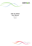
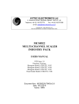
HYTEC ELECTRONICS Ltd
HEAD OFFICE: 5 Cradock Road, Reading, Berkshire, RG2 0JT, UK
Telephone: +44 118 9757770 Fax: +44 118 9757566
E-mail: [email protected]
Web:www.hytec-electronics.co.uk
DAC8404
16-CHANNEL 16-BIT DAC
INDUSTRY PACK
User Manual
Document Nos.: DAC8404/ UTM/1.0
Date: 1/10/2008
Author: AB/MCB/DAN
Hytec Electronics Ltd
DAC8404/UTM/x/1.0
Date 11/07/07
CONTENTS
1.
FEATURES..........................................................................................................................................3
2.
PRODUCT SPECIFICATIONS ........................................................................................................3
3.
OPERATING MODES .......................................................................................................................4
3.1
3.2
USING REGISTERS TO UP DATE DACS ..................................................................................4
USING MEMORY TO UP DATE DACS .....................................................................................4
4.
MEMORY MAP..................................................................................................................................5
5.
APPLICATION REGISTERS ...........................................................................................................5
5.1
5.2
5.3
5.4
5.5
5.6
5.7
5.8
5.9
CONTROL & STATUS REGISTER (CSR)..........................................................................................6
MEMORY POINTER.........................................................................................................................7
NUMBER OF UPDATES 1.................................................................................................................7
CLOCK RATE..................................................................................................................................7
INTERRUPT VECTOR ......................................................................................................................7
FULL-SCALE TRIM & ID PAGE NO.................................................................................................8
NUMBER OF UPDATES 2.................................................................................................................8
DAC DATA REGISTERS .................................................................................................................9
DAC COMMAND REGISTERS .......................................................................................................10
6.
ID PROM ...........................................................................................................................................11
7.
CALIBRATION ................................................................................................................................12
7.1
7.2
7.3
7.4
7.5
7.6
7.7
7.8
BIPOLAR CALIBRATION FORMULA ..............................................................................................12
UNI-POLAR CALIBRATION FORMULA ..........................................................................................13
ID PAGE 1 (PG2 = 0, PG1 = 0, PG0 = 1) +/- 10V SCAN CALIBRATION VALUES LAYOUT...........14
ID PAGE 2 (PG2 = 0, PG1 = 1, PG0 = 0) +/- 10V SCAN CALIBRATION VALUES LAYOUT...........15
ID PAGE 3 (PG2 = 0, PG1 = 1, PG0 = 1) +/- 10V SCAN CALIBRATION VALUES LAYOUT...........16
ID PAGE 4 (PG2 = 1, PG1 = 0, PG0 = 1) +10V SCAN CALIBRATION VALUES LAYOUT. .............17
ID PAGE 5 (PG2 =1, PG1 = 1, PG0 = 0) +10V SCAN CALIBRATION VALUES LAYOUT...............17
ID PAGE 6 (PG2 = 1. PG1 = 1, PG0 = 1) +10V SCAN CALIBRATION VALUES LAYOUT. .............18
8.
SELECTION OF THE +/-12 VOLT POWER SUPPLY ...............................................................20
9.
I/O CONNECTOR – 50 WAY ON 8404 DAC BOARD.................................................................21
10.
HYTEC TRANSITION CARD 8204 CONNECTIONS ............................................................22
11.
APPENDIX A: PSEUDO CODE EXAMPLES ..........................................................................23
11.1
11.2
DAC UPDATE BY REGISTER.........................................................................................................23
UPDATE DAC FROM WAVEFORM MEMORY DATA .....................................................................23
Page 2 of 23
Hytec Electronics Ltd
DAC8404/UTM/x/1.0
Date 11/07/07
1. Features
The Hytec IP-DAC-8404 is a single-width Industry Pack that provides 16 channels of
simultaneously updated digital to analogue conversion with the following characteristics:•
•
•
•
•
•
•
•
•
•
•
•
•
•
•
•
•
•
•
•
16 independently programmed channels
5 programmable ranges per channel 0-5V, 0-10V +/-5V, +/-10V and +/-2.5V
16 bits resolution
64K samples per channel memory.
Registered or memory fetch updates.
Two independent digitally controlled full-scale trims for each group of eight channels.
Low offset error - +/-5mV typical (With software Cal applied +/-0.5mV)
Low gain error - +/-5LSBs typical (With software Cal applied +/-2.5LSBs typ.+/-4.5LSBs
max)
Low error drift - 2ppm per deg C
+/- 10mA current drive capability with continuous short-circuit protection
Straight binary code
10KHz update rate
Power-On Reset to 0V
100V system to plant isolation when externally powered
Board serial number, PCB issue and firmware version held on ROM.
External Triggering
Continuous function generation.
Internal/External update clock rates
Internal update clock rates programmable
(10KHz,5KHz,2KHz,1KHz,500Hz,200Hz,100Hz,50Hz,20Hz,10Hz,5Hz,2Hz and 1Hz)
Pin-out compatible with DAC8402 (in command default mode).
2. Product Specifications
Size:
Single width Industry Pack 1.8ins x 3.9 ins
Operating temp:
0 to 45 deg C ambient
Number of channels: 16
DAC resolution:
16 bits
Data format:
16 bits binary
Range: Programmable 0V to 5V, 0V to 10V, +/-5V, +/-10V, and +/-2.5V FSR (Full Scale
Reading)
Output current:
+/-10mA @ FS
Capacitive load:
Stable up to 20,000pF
Short circuit duration: Continuous
OverV withstand:
No internal protection from external voltages provided
Update rate:
10KHz max
Power:
+5V @ 300mA typical
+/-12V @ 120mA typical when switched to internal (external load
dependent)
Isolation:
100V via opto-isolators (if externally powered)
Integral non-linearity: +/-1LSB max
Diff non-linearity:
+/-1LSB max
Offset error:
+/-200uV max
Gain drift:
3ppm per deg C
Gain error:
+/-5LSBs typ. +/-16LSBs max.
Output slew rate:
+/-13V/us min.
Settling time:
20us max.to 0.005% of final value for 1000pF load capacitance
Page 3 of 23
Hytec Electronics Ltd
DAC8404/UTM/x/1.0
Date 11/07/07
3. Operating Modes
There are two operating modes:1. Registered – the DAC outputs are controlled by the contents of the DAC registers.
2. Memory – the outputs are updated for the programmed number of samples at the
programmed clock rate.
All the outputs are updated serially but change together (there will be slight changes due to
differences in the slew rate of the amplifiers (about +/-1uS) at the end of an internal update
cycle.
The outputs may be updated at a rate of up to 10KHz. The two methods to update the 8404
DACs are detailed below.
3.1 USING REGISTERS TO UP DATE DACs
There are 16 individual DACs on the IP Card with 16 Data & Command DAC registers to access
each one. This allows the user to set if required each DAC to different voltage ranges. The
DACs are serially loaded with a 32 bit data stream comprising of the first 16 bits with the
command word, to set the required voltage range, and the last 16 bits correspond to the data to
set the output of the DAC to. Therefore, both the data and command registers must both be set
the DACs to operate correctly.
The DACs are arranged in two groups, DACs 1 to 8 are daisy chained together to form bank A
and DACs 9 to 16 daisy chained to form bank B.
Once the registers have been loaded, the module can then be ARMed and the data from the
registers will be serially loaded from one DAC to the next until all the data has been passed to
all of the DACs. At this point the DAC outputs are automatically updated giving 16 simultaneous
outputs. While the unit is ARMed the DACs are constantly refreshed with the contents of the
registers which can be changed during this time. There is a delay which is fixed of
approximately 32us after ARM is set, before all the outputs change together.
3.2 USING MEMORY TO UP DATE DACs
In this mode the data to be sent to the DACs is loaded from memory instead of the DAC Data
register, however the command for each DAC is still required, but only has to be set once at the
start. Once the DAC Command has been set this remains unchanged, unless the voltage range
is changed, then the new command must be written again.
The onboard memory is first loaded with the required data and the number of memory locations
used is entered in to the Number of Updates (NCO) register. With the DAC Command Register
already written and set, the Control and Status Register (CSR) is then set to enable memory
updates and ARM to unit with a software command. A trigger can then be issued either by a
software command or by an external trigger to start down loading the data held in memory to
the DACs via the registers as detail above. In this mode the registers are updated with new
data from the memory at the update clock rate which is derived either internally or externally.
The memory address is automatically incremented.
When the programmed number of output has occurred the unit will stop and generate an
interrupt if enabled or if set in continues mode the address counter will be zeroed and the output
repeated (no interrupt generated in continues mode) until the ARM bit is cleared or the
continues bit CC in the CSR is cleared.
Page 4 of 23
Hytec Electronics Ltd
DAC8404/UTM/x/1.0
Date 11/07/07
4. Memory Map
There are two main buffer memories of 512k updates each (lower and upper buffers)
These are each divided into sixteen segments allocated to updates for DAC1 to DAC16.
When DAC16 has been updated from the top of the lower buffer, the Half Full Flag status is set
and when it has been updated from the top of the upper memory buffer the Full Flag status is
set.
Lower Conversion Memory
DAC16 conversions
DAC15 conversions
DAC14 conversions
DAC13 conversions
DAC12 conversions
DAC11 conversions
DAC10 conversions
DAC9 conversions
DAC8 conversions
DAC7 conversions
DAC6 conversions
DAC5 conversions
DAC4 conversions
DAC3 conversions
DAC2 conversions
DAC1 conversion 32k
DAC1 conversion 32k-1
DAC1 conversion 2
DAC1 conversion 1
Upper Conversion Memory
DAC16 conversions
DAC15 conversions
DAC14 conversions
DAC13 conversions
DAC12 conversions
DAC11 conversions
DAC10 conversions
DAC9 conversions
DAC8 conversions
DAC7 conversions
DAC6 conversions
DAC5 conversions
DAC4 conversions
DAC3 conversions
DAC2 conversions
DAC1 conversion 64k
DAC1 conversion 64k-1
DAC1 conversion 32k+2
DAC1 conversion 32k+1
.
5. Application Registers
There are eight application specific (I/O) registers; the CSR, the number of samples per trigger,
the Conversion Pointer, Clock Rate, Interrupt Vector, Full Scale Trim & ID Page No, DAC Data
Registers and DAC Command Registers.
Page 5 of 23
Hytec Electronics Ltd
DAC8404/UTM/x/1.0
Date 11/07/07
5.1 Control & Status Register (CSR)
Read/Write Address: 0 hex
D15 D14 D13 D12 D11 D10 D09 D08 D07 D06 D05 D04 D03 D02 D01 D00
ARM EX ST XC ET EE FE HE
0
0 1MB MH CONT CC
F
HF
ARM Writing a ‘1’ to ARM bit causes the values loaded in to the DAC registers or the memory
to be loaded in to the DACs.
When all the DACs have been updated from the registers (the EX bit set to ‘0’) the ARM
bit is cleared.
If the DACs are being updated from the memory (the EX bit set to ‘1’) the ARM bit is not
cleared.
In this mode if a number of triggers occur which cause the end of the memory to be
reached, a subsequent trigger will cause the memory pointer to wrap around to the start
of memory.
EX
Enable trigger and memory update.
EX=0 If not set the outputs will be enabled from the registers transparently.
EX=1 If set allows external trigger or software trigger to initiate programmed updates
from memory. In this mode the Number Of Updates Register needs to be set between 0
to 64K updates.
ST
Software trigger. Triggers a programmed number of updates from the memory as set by
the Number of Updates register.
XC
Enable the external clock. 0 = internal clock used for the sample rate. 1 = external clock
used for the sample rate.
ET
When set to ‘1’ enables signal the Inhibit Lemo of the 8002 via the IP Strobe line. The
Inhibit signal when set stops the updating DAC from memory.
EE
Enables interrupt at end of programmed number of DAC updates from memory.
FE
Enables interrupt when the upper conversion memory
has been filled. (Memory Full).
HE
Enables interrupt when the lower conversion memory has been filled. (Memory Half
Full).
1MB
Enable 1Mb memory, (32K values/channel), when logic 1 and 2Mb (64K
values/channel) when logic 0.
MH
Set to ‘1’ when the memory is inhibited from the IP Strobe line and ET set.
CONT Sets continues function generation
CC
Conversions complete. Status bit set when the number of programmed updates has
been completed. Generates IRQ0* if set and EE is set to a logic 1.
F
Full status. Set when DAC16 has been updated from the top of memory. Generates
IRQ0* if set and FE is set to a logic 1.
HF
Half full status. Set when DAC16 has been updated from the top of the lower memory
buffer. Generates IRQ0* if set and HE is set to a logic 1.
Page 6 of 23
Hytec Electronics Ltd
DAC8404/UTM/x/1.0
Date 11/07/07
5.2 Memory Pointer
Read/write Address: 2 hex
The current conversion address is given by the conversion base address offset by the DAC
number and for mode 0 the Half Full status. The buffer pointer base address is the number of
updates output.
D15 D14 D13 D12 D11 D10 D09 D08 D07 D06 D05 D04 D03 D02 D01 D00
C15 C14 C13 C12 C11 C10 C9 C8 C7 C6 C5 C4 C3 C2 C1 C0
5.3 Number of Updates 1
Read/write Address: 4 hex
The number of updates register allows the number of updates per trigger to be programmed. It
is basically which sample to start a memory waveform output from. If the memory buffer size is
exceeded the update values will wrap around from the upper memory to the base of the lower
memory. Number of Updates 1 and Number of Updates 2 should be set to the same value.
D15 D14 D13 D12 D11 D10 D09 D08 D07 D06 D05 D04 D03 D02 D01 D00
N15 N14 N13 N12 N11 N10 N9 N8 N7 N6 N5 N4 N3 N2 N1 N0
Note 1: If DACs are being driven by the DAC Data Registers (10 – 1E Hex) rather than from the
Waveform Memory then both Number of Updates registers must be loaded with FFFF Hex.
Note 2: If ‘0’ is entered in to the Number of Updates register then the whole of the memory will
be used to update the DACs.
5.4 Clock Rate
Read/write Address: 6 hex
The clock rate register allows you to set all 16 channels conversion frequency. It comprises of
two four bit register (D00 to D03 and D04 to D07) both are written with codes 0 – 12 to generate
frequencies of 1 Hz to 10 kHz in multiples of 1, 2, 5 or 10. (E.g. 0=1Hz, 1=2Hz, 2=5Hz, 3=10Hz
and so on up to 10KHz).
Note: Both four bit registers must be loaded with the same desired clock rate value.
D15 D14 D13 D12 D11 D10 D09 D08 D07 D06 D05 D04 D03 D02 D01 D00
X
X
X
X
X
X
X
X
F03 F02 F01 F00 F03 F02 F01 F00
5.5 Interrupt Vector
Read/write Address: 8 hex
The vector register is a 16 bit register which stores the interrupt vector value.
D15
V15
D14
V14
D13
V13
D12
V12
D11
V11
D10
V10
D09
V9
D08
V8
D07
V7
Page 7 of 23
D06
V6
D05
V5
D04
V4
D03
V3
D02
V2
D01
V1
D00
V0
Hytec Electronics Ltd
DAC8404/UTM/x/1.0
Date 11/07/07
5.6 Full-scale Trim & ID Page No
Read/write Address: A hex
D15
PG2
D14
PG1
D13
PG0
D12
D11
D10
D09
D08
D07
D06
D05
D04
U/D
D03
STORE
D02
S2
D01
S1
D00
INC
This first 5 bits D00 to D04 are used to control the resistor pot adjustments for the voltage
reference to the DACs. There are 2 pots that can set the voltage reference for the common
DACs 1-8(Bank A) and 9-16 (Bank B). There are 100 steps of approximately 1 bit/step per one
of two gain adjustments selected by S1 or S2.
INC
When asserted INC causes 1 step of adjustment up or down, dependent upon the U/D
setting and if S1 or S2 are set.
S1 Select Voltage reference adjustment for bank A (DAC 1-8)
S2 Select Voltage reference adjustment for bank B (DAC 9-16)
STORE When high the current setting is stored in non-volatile memory.
U/D
Programs the direction of the wiper adjustment. (Up=0, Down = 1)
For example to increment the wiper position on S1 set S1, INC high. To decrement S2 wiper
position set S2, U/D and INC high
.
PG0
Bit 0 of ID PROM Paging.*
PG1
Bit 1 of ID PROM Paging.*
PG2
Bit 2 of ID PROM Paging.*
*Since some carrier devices only support 64 locations in the ID PROM and the 8404 have up to
80 16-bit calibration values. Therefore it is required to page the ID PROM; these three bits are
used to switch between pages of the ID PROM.
PG2
0
0
0
0
1
1
1
PG1
0
0
1
1
0
1
1
PG0
0
1
0
1
1
0
1
PAGE
0 (Default)
1
2
3
4
5
6
NOTES
Normal VITA4 format for ID PROM.
Calibration Values for +/-V Scan DAC Channel 0-5.
Calibration Values for +/-V Scan DAC Channel 6-11.
Calibration Values for +/-V Scan DAC Channel 12-16.
Calibration Values for +V Scan DAC Channel 0-5.
Calibration Values for +V Scan DAC Channel 6-11.
Calibration Values for +V Scan DAC Channel 12-16.
5.7 Number of Updates 2
Read/write Address: E hex
See Number of Updates 1
D15 D14 D13 D12 D11 D10 D09 D08 D07 D06 D05 D04 D03 D02 D01 D00
N15 N14 N13 N12 N11 N10 N9 N8 N7 N6 N5 N4 N3 N2 N1 N0
Page 8 of 23
Hytec Electronics Ltd
DAC8404/UTM/x/1.0
Date 11/07/07
5.8 DAC Data Registers
Read/write Address: 10hex – 1Ehex
The 16 DACs are updated by these registers whenever they are overwritten and the EX bit is
zero.
Dependent upon the voltage range the data format is straight binary, as shown in the table
below:D15
B15
D14
B14
D13
B13
Bipolar Voltage
Range
+/-10V
+/-5V
+/-2.5V
Uni-polar
Voltage Range
+10V
+5V
D12
B12
D11
B11
D10
B10
Negative Full
Scale
0Hex
0Hex
0Hex
Zero
0Hex
0Hex
D09
B9
D08
B8
D07
B7
D06
B6
Zero
8000h
8000h
8000h
Positive-Half
Scale
8000h
8000h
Table showing data format dependent upon Voltage Range
Page 9 of 23
D05
B5
D04
B4
D03
B3
Positive Full
Scale
7FFF Hex
7FFF Hex
7FFF Hex
Positive Full
Scale
7FFF Hex
7FFF Hex
D02
B2
D01
B1
D00
B0
Hytec Electronics Ltd
DAC8404/UTM/x/1.0
Date 11/07/07
5.9 DAC Command Registers
Read/write Address 30-4E hex
The command registers are used in conjunction with the DAC data registers. Due to the nature
of the DACs the data and command registers must be set at the same time because the
information is serially transferred to the DACs. Each DAC requires a 32 bit serial data stream,
the first 16 bits form the command word and the last 16bits form the data to be written to the
DACs. If the user wants to change the voltage range these command registers require
modifying to reflect the range required. This allows each DAC to be at different voltage ranges if
required.
D07
C3
D06
C2
D05
C1
D04
C0
D03
0
D02
0
D01
0
D00
0
Command Code (hex)
Action
Copy data in Shift Register to Buffer 1
0
Copy the data in Buffer 1 to Buffer 2
1
Copy the data in Shift Register to Buffers 1 & 2
2
Not used
3
Not used
4
Not used
5
Not used
6
Not used
7
Set Range to 5V. Copy data in SR to Buffers 1 & 2.
8
Set Range to 10V. Copy data in SR to Buffers 1 & 2.
9
Set Range to +/-5V. Copy data in SR to Buffers 1 & 2.
10
Set Range to +/-10V. Copy data in SR to Buffers 1 & 2.
11
Set Range to +/-2.5V. Copy data in SR to Buffers 1 & 2.
12
Set Range to –2.5V to 7.5V. Copy data in SR to Buffers 1&2.
13
Not used.
14
No operation – no change.
On power up this register is set to zero and therefore must be set before the unit can be used
as an initial setup. The DAC can be set to various modes of operation; the voltage ranges
supported are +/-10V, 0V to +5V, 0V to +10V, +/-5V and +/-2.5V, which are hex codes 11, 8, 9,
10 and 12 respectively
Page 10 of 23
Hytec Electronics Ltd
DAC8404/UTM/x/1.0
Date 11/07/07
6. ID PROM
As some IP Carrier Cards only support 64 16-Bit locations in the ID Space, we page the ID
Space to provide extra space for DAC calibration data. To switch between pages, there are
control bits in Full-Scale Trim & ID Page No Register (A Hex). The default setting is the
standard ‘VITA4’ layout, but there are additional pages as shown below…
PG2
0
0
0
0
1
1
1
PG1
0
0
1
1
0
1
1
PG0
0
1
0
1
1
0
1
PAGE
0 (Default)
1
2
3
4
5
6
NOTES
Normal VITA4 format for ID PROM.
Calibration Values for +/-V Scan DAC Channel 0-5.
Calibration Values for +/-V Scan DAC Channel 6-11.
Calibration Values for +/-V Scan DAC Channel 12-16.
Calibration Values for +V Scan DAC Channel 0-5.
Calibration Values for +V Scan DAC Channel 6-11.
Calibration Values for +V Scan DAC Channel 12-16.
The +/- calibration factors are stored under pages 1 to 3. These are calculated for the +/-10V
range, but these figures can be used to correct the errors for the +/-5V and +/-2.5V ranges.
Similarly the positive calibration figures are stored under pages 4 to 6 and are calculated for the
+10V range, but can also be used to correct errors on the +5V range.
The word addresses are as below:Base+80 ASCII ‘VI’
5649h
Base+82 ASCII ‘TA’
5441h
Base+84 ASCII ‘4 ‘
3420h
Base+86 Hytec ID high byte 0080h
Base+88 Hytec ID low word 0300h
Base+8A Model number
8404h
Base+8C Revision
1101h This shows PCB Iss 1 Xilinx V101
Base+8E Reserved
0000h
Base+90 Driver ID
0000h
Base+92 Driver ID
0000h
Base+94 Flags
0002h
Base+96 No of bytes used
001Ah
Base+98 Cal Type
xxxxh 0 = No Calibration, 1 = Calibration factors Stored.
Base+9A Serial Number
xxxxdec
Base+9C Not used
xxxxh
Base+9E WLO
5555h
Page 11 of 23
Hytec Electronics Ltd
DAC8404/UTM/x/1.0
Date 11/07/07
7. Calibration
The type of calibration factors held in the ID PROM are specified by the Cal Type held at
Base+98 in the ID PROM:0 = No Calibration factors held in ID PROM.
1 = 3 Point Calibration factors Stored in ID PROM.
The Calibration Factors are held in the ID PROM pages 1 to 3 as shown the following Tables
and as described in SECTION 7. These are the stored DAC values, derived from reading the
DAC at the following specified voltages…
Value
nFS
zero
pFS
Bipolar Calibration
Voltage
-10V
0V
+10V
Bipolar Voltage
Range
+/-10V
+/-5V
+/-2.5V
Uni-polar
Voltage Range
+10V
+5V
Calibration range
Negative Full
Scale
40Hex
40Hex
40Hex
Zero
DHex
DHex
Value
zero
pHS
pFS
Zero
8000h
8000h
8000h
Positive-Half
Scale
8000h
8000h
Uni-polar Calibration
Voltage
0V
+5V
+10V
Positive Full
Scale
7FC0Hex
7FC0Hex
7FC0Hex
Positive Full
Scale
7FC0Hex
7FC0Hex
These values can then be used in the following equations to correct the offset and gain errors of
the individual cannels of the DAC8404 IP card.
7.1 Bipolar Calibration Formula
rawval > zero
( pFS − zero ) × (rawval − 0 x8000) + zero
CalVal =
0 x7 FC 0
rawval < zero
(zero − nFS ) × (rawval − 0 x8000) + zero
CalVal =
0 x7 FC 0
Page 12 of 23
Hytec Electronics Ltd
DAC8404/UTM/x/1.0
7.2 Uni-polar Calibration Formula
rawval > zero
rawval > pHS
( pFS − zero ) × (rawval )
CalVal =
0xFFC 0
rawval > zero
rawval < pHS
( pHS − zero ) × (rawval )
CalVal =
0 x7 FE 0
rawval < zero
(zero − 0) × (rawval )
CalVal =
0 x000 D
Page 13 of 23
Date 11/07/07
Hytec Electronics Ltd
DAC8404/UTM/x/1.0
Date 11/07/07
7.3 ID Page 1 (PG2 = 0, PG1 = 0, PG0 = 1) +/- 10V Scan Calibration Values Layout.
The layout of the calibration pages is additionally dependant on the ‘Cal Type’ Value from the
Default (Page 0) page of the ID PROM Section.
Address
Base+80
Base+82
Base+84
Base+86
Base+88
Base+8A
Base+8C
Base+8E
Base+90
Base+92
Base+94
Base+96
Base+98
Base+9A
Base+9C
Base+9E
Base+A0
Base+A2
Base+A4
Base+A6
Base+A8
Base+AA
Base+AC
Base+AE
Base+B0
Base+B2
Base+B4
Base+B6
Base+B8
Base+BA
Cal Type = 1
DAC0 Cal data nFS
DAC0 Cal data Zero
DAC0 Cal data pFS
DAC1 Cal data nFS
DAC1 Cal data Zero
DAC1 Cal data pFS
DAC2 Cal data nFS
DAC2 Cal data Zero
DAC2 Cal data pFS
DAC3 Cal data nFS
DAC3 Cal data Zero
DAC3 Cal data pFS
DAC4 Cal data nFS
DAC4 Cal data Zero
DAC4 Cal data pFS
DAC5 Cal data nFS
DAC5 Cal data Zero
DAC5 Cal data pFS
Table Key Cal data nFS - Negative Full Scale Calibration Factor.
Cal data Zero- Zero (0 Volts) Calibration Factor.
Cal data pFS - Positive Full Scale Calibration Factor.
Page 14 of 23
Hytec Electronics Ltd
DAC8404/UTM/x/1.0
Date 11/07/07
7.4 ID Page 2 (PG2 = 0, PG1 = 1, PG0 = 0) +/- 10V Scan Calibration Values Layout.
The layout of the calibration pages is additionally dependant on the ‘Cal Type’ Value from the
Default (Page 0) page of the ID PROM Section.
Address
Base+80
Base+82
Base+84
Base+86
Base+88
Base+8A
Base+8C
Base+8E
Base+90
Base+92
Base+94
Base+96
Base+98
Base+9A
Base+9C
Base+9E
Base+A0
Base+A2
Base+A4
Base+A6
Base+A8
Base+AA
Base+AC
Base+AE
Base+B0
Base+B2
Base+B4
Base+B6
Base+B8
Base+BA
Cal Type = 1
DAC6 Cal data nFS
DAC6 Cal data Zero
DAC6 Cal data pFS
DAC7 Cal data nFS
DAC7 Cal data Zero
DAC7 Cal data pFS
DAC8 Cal data nFS
DAC8 Cal data Zero
DAC8 Cal data pFS
DAC9 Cal data nFS
DAC9 Cal data Zero
DAC9 Cal data pFS
DAC10 Cal data nFS
DAC10 Cal data Zero
DAC10 Cal data pFS
DAC11 Cal data nFS
DAC11 Cal data Zero
DAC11 Cal data pFS
Table Key Cal data nFS - Negative Full Scale Calibration Factor.
Cal data Zero - Zero (0 Volts) Calibration Factor.
Cal data pFS - Positive Full Scale Calibration Factor.
Page 15 of 23
Hytec Electronics Ltd
DAC8404/UTM/x/1.0
Date 11/07/07
7.5 ID Page 3 (PG2 = 0, PG1 = 1, PG0 = 1) +/- 10V Scan Calibration Values Layout.
The layout of the calibration pages is additionally dependant on the ‘Cal Type’ Value from the
Default (Page 0) page of the ID PROM Section.
Address
Base+80
Base+82
Base+84
Base+86
Base+88
Base+8A
Base+8C
Base+8E
Base+90
Base+92
Base+94
Base+96
Base+98
Base+9A
Base+9C
Base+9E
Base+A0
Base+A2
Base+A4
Base+A6
Base+A8
Base+AA
Base+AC
Base+AE
Base+B0
Base+B2
Base+B4
Base+B6
Base+B8
Base+BA
Cal Type = 1
DAC12 Cal data nFS
DAC12 Cal data Zero
DAC12 Cal data pFS
DAC13 Cal data nFS
DAC13 Cal data Zero
DAC13 Cal data pFS
DAC14 Cal data nFS
DAC14 Cal data Zero
DAC14 Cal data pFS
DAC15 Cal data nFS
DAC15 Cal data Zero
DAC15 Cal data pFS
Table Key Cal data nFS - Negative Full Scale Calibration Factor.
Cal data Zero - Zero (0 Volts) Calibration Factor.
Cal data pFS - Positive Full Scale Calibration Factor.
Page 16 of 23
Hytec Electronics Ltd
DAC8404/UTM/x/1.0
Date 11/07/07
7.6 ID Page 4 (PG2 = 1, PG1 = 0, PG0 = 1) +10V Scan Calibration Values Layout.
The layout of the calibration pages is additionally dependant on the ‘Cal Type’ Value from the
Default (Page 0) page of the ID PROM Section.
Address
Base+80
Base+82
Base+84
Base+86
Base+88
Base+8A
Base+8C
Base+8E
Base+90
Base+92
Base+94
Base+96
Base+98
Base+9A
Base+9C
Base+9E
Base+A0
Base+A2
Base+A4
Base+A6
Base+A8
Base+AA
Base+AC
Base+AE
Base+B0
Base+B2
Base+B4
Base+B6
Base+B8
Base+BA
Cal Type = 1
DAC0 Cal data zero
DAC0 Cal data pHS
DAC0 Cal data pFS
DAC1 Cal data zero
DAC1 Cal data pHS
DAC1 Cal data pFS
DAC2 Cal data zero
DAC2 Cal data pHS
DAC2 Cal data pFS
DAC3 Cal data zero
DAC3 Cal data pHS
DAC3 Cal data pFS
DAC4 Cal data zero
DAC4 Cal data pHS
DAC4 Cal data pFS
DAC5 Cal data zero
DAC5 Cal data pHS
DAC5 Cal data pFS
Table Key Cal data Zero - Zero (0 Volts) Calibration Factor.
Cal data pHS - Positive Half-Full Scale Calibration Factor.
Cal data pFS - Positive Full Scale Calibration Factor.
7.7 ID Page 5 (PG2 =1, PG1 = 1, PG0 = 0) +10V Scan Calibration Values Layout.
Page 17 of 23
Hytec Electronics Ltd
DAC8404/UTM/x/1.0
Date 11/07/07
The layout of the calibration pages is additionally dependant on the ‘Cal Type’ Value from the
Default (Page 0) page of the ID PROM Section.
Address
Base+80
Base+82
Base+84
Base+86
Base+88
Base+8A
Base+8C
Base+8E
Base+90
Base+92
Base+94
Base+96
Base+98
Base+9A
Base+9C
Base+9E
Base+A0
Base+A2
Base+A4
Base+A6
Base+A8
Base+AA
Base+AC
Base+AE
Base+B0
Base+B2
Base+B4
Base+B6
Base+B8
Base+BA
Cal Type = 1
DAC6 Cal data zero
DAC6 Cal data pHS
DAC6 Cal data pFS
DAC7 Cal data zero
DAC7 Cal data pHS
DAC7 Cal data pFS
DAC8 Cal data zero
DAC8 Cal data pHS
DAC8 Cal data pFS
DAC9 Cal data zero
DAC9 Cal data pHS
DAC9 Cal data pFS
DAC10 Cal data zero
DAC10 Cal data pHS
DAC10 Cal data pFS
DAC11 Cal data zero
DAC11 Cal data pHS
DAC11 Cal data pFS
Table Key Cal data Zero - Zero (0 Volts) Calibration Factor.
Cal data pHS - Positive Half-Full Scale Calibration Factor.
Cal data pFS - Positive Full Scale Calibration Factor.
7.8 ID Page 6 (PG2 = 1. PG1 = 1, PG0 = 1) +10V Scan Calibration Values Layout.
Page 18 of 23
Hytec Electronics Ltd
DAC8404/UTM/x/1.0
Date 11/07/07
The layout of the calibration pages is additionally dependant on the ‘Cal Type’ Value from the
Default (Page 0) page of the ID PROM Section.
Address
Base+80
Base+82
Base+84
Base+86
Base+88
Base+8A
Base+8C
Base+8E
Base+90
Base+92
Base+94
Base+96
Base+98
Base+9A
Base+9C
Base+9E
Base+A0
Base+A2
Base+A4
Base+A6
Base+A8
Base+AA
Base+AC
Base+AE
Base+B0
Base+B2
Base+B4
Base+B6
Base+B8
Base+BA
Cal Type = 1
DAC12 Cal data zero
DAC12 Cal data pHS
DAC12 Cal data pFS
DAC13 Cal data zero
DAC13 Cal data pHS
DAC13 Cal data pFS
DAC14 Cal data zero
DAC14 Cal data pHS
DAC14 Cal data pFS
DAC15 Cal data zero
DAC15 Cal data pHS
DAC15 Cal data pFS
Table Key Cal data Zero - Zero (0 Volts) Calibration Factor.
Cal data pHS - Positive Half-Full Scale Calibration Factor.
Cal data pFS - Positive Full Scale Calibration Factor.
Page 19 of 23
Hytec Electronics Ltd
DAC8404/UTM/x/1.0
Date 11/07/07
8. SELECTION OF THE +/-12 VOLT POWER SUPPLY
The DAC 8404 +/-12 volt power supply can be derived either internally from the carrier card or from an
external source via a transition card. The source is selected using jumpers J1, J2 and the GND AGND
link LNK1 where:
J1 External +12V connect 1 & 2, Internal +12V connect 2 & 3
J2 External -12V connect 1 & 2, Internal -12V connect 2 & 3
J3 Make link to boot FPGA from PROM (Factory setting), remove to use JTAG test header
LNK1 (GND AGND)
IN for internal +/-12V
OUT for external +/-12V (supplied from transition card DC DC converter).
Page 20 of 23
Hytec Electronics Ltd
DAC8404/UTM/x/1.0
Date 11/07/07
9. I/O Connector – 50 way on 8404 DAC Board
Pin
1
2
3
4
5
6
7
8
9
10
11
12
13
14
15
16
17
18
19
20
21
22
23
24
25
Signal
Output 1
AGND
Output 2
AGND
Output 3
AGND
Output 4
AGND
Output 5
AGND
Output 6
AGND
Output 7
AGND
Output 8
AGND
Output9
AGND
Output10
AGND
Output11
AGND
Output12
AGND
Output13
Page 21 of 23
Pin
26
27
28
29
30
31
32
33
34
35
36
37
38
39
40
41
42
43
44
45
46
47
48
49
50
Signal
AGND
Output14
AGND
Output15
AGND
Output16
AGND
N.C.
N.C.
XTrigger
/XTrigger
N.C.
N.C.
XClk
/XClk
+12VX
AGND
+12VX
AGND
-12VX
AGND
-12VX
AGND
N.C.
AGND
Hytec Electronics Ltd
DAC8404/UTM/x/1.0
Date 11/07/07
10.HYTEC TRANSITION CARD 8204 CONNECTIONS
I/O Connector – 50 way on transition panel
Pin
1
2
3
4
5
6
7
8
9
10
11
12
13
14
15
16
17
18
19
20
21
22
23
24
25
Signal
AGND
AGND
AGND
AGND
AGND
AGND
AGND
AGND
AGND
AGND
AGND
AGND
AGND
AGND
AGND
AGND
XTRIG N
XCLK N
AGND
AGND
Pin
26
27
28
29
30
31
32
33
34
35
36
37
38
39
40
41
42
43
44
45
46
47
48
49
50
Page 22 of 23
Signal
Output1
Output 2
Output 3
Output 4
Output 5
Output 6
Output 7
Output 8
Output 9
Output 10
Output 11
Output 12
Output 13
Output 14
Output 15
Output 16
XTRIG P
XCLK P
AGND
AGND
Hytec Electronics Ltd
DAC8404/UTM/x/1.0
Date 11/07/07
11. Appendix A: Pseudo Code Examples
11.1 DAC update by Register
The following pseudo code is the sequence of actions required to immediately update any DAC
Channel’s output via the Data Registers.
1. Update Clock Rate Register. The Desired Clock Rate MUST Be Written to Both
Nibbles of Least Significant Byte of the Clock Rate Register.
2. Both Number of Update Registers MUST Be Loaded with 0xFFFF.
3. Set the DAC Voltage Range via the relevant DAC Command Register.
4. Write DAC Value to the output via the relevant DAC Data Register.
5. Set the Arm bit in CSR.
11.2 Update DAC from Waveform Memory Data
The following pseudo code is the sequence of actions required to allow a waveform from
memory update of any DAC Channel’s output. It assumes the 1 Mb Version of the 8404 is
being used and the output will be triggered by the software.
1.
2.
3.
4.
5.
6.
7.
8.
Ensure the DAC is disarmed (i.e. the Arm bit in the CSR is NOT set).
Ensure the 1Mb Memory Bit in the CSR is Set.
Set the DAC Voltage Range via the relevant DAC Command Register.
Write the initial Waveform Value to the output (via the relevant DAC Data
Register).
Write 32K of 16 Bit Samples of the required Waveform into the desired DAC
channel’s Memory.
Both Upgrade Registers MUST Be Loaded with 0 (For Whole Memory)
Setup Waveform Output by arming the DAC and allowing it to accept a trigger,
i.e. set the arm and external trigger bits in the CSR. If you want the output to be
cyclically continuously updated from the memory also set the continuous bit in
the CSR at the same time.
To start the waveform output set the software trigger bit in the CSR.
Page 23 of 23