1
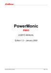
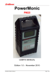
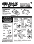
LineIQ
Battery Charger
USER MANUAL
Edition 1.1 – August 2012
LineIQ Battery Charger
Document No. : GSN-DC-103
28 Aug 2012 Edition 1.0 Page 1 of 13
LineIQ Battery Charger User Manual
© CHK GridSense Pty Ltd 2012
The material presented in this manual is copyright protected by CHK GridSense Pty Ltd
2012. Any reproduction in whole or part for any purpose without the prior written consent of
CHK GridSense Pty Ltd is strictly prohibited. Information in this document is subject to
change without notice.
All trademarks are property of their respective owners.
Printed in Australia
AUSTRALIA / NEW ZEALAND EMC NOTES
N3207
This is a CISPR 22 Class A product. In a domestic
environment this product may cause radio
interference, which the user may need to take steps to
prevent.
LIMITED WARRANTY
The LineIQ Battery Charger is guaranteed to be free of mechanical and electrical defects
when dispatched from our store. Provided that the LineIQ Battery Charger has been operated
within its normal ratings as specified, it will be repaired or replaced free of charge if, within a
period of twelve (12) months from date of our invoice to the original purchase, it is proven,
upon examination by our engineers, to be defective in material or workmanship. This
warranty is void if the unit has been tampered with, abused or if the defect is related to
service not performed by CHK GridSense Pty Ltd.
Responsibility of CHK GridSense Pty Ltd: Under this guarantee, the responsibility of CHK
GridSense Pty Ltd is limited to the repairing or replacing of any defective part provided the
instrument is returned freight paid to and from our Testing and Service office in Sydney, NSW
Australia.
LineIQ Battery Charger
Document No. : GSN-DC-103
28 Aug 2012 Edition 1.0 Page 2 of 13
TABLE OF CONTENTS
1.
2.
THE LINEIQ BATTERY CHARGER .......................................................................................4
LINEIQ CHARGER OVERVIEW ............................................................................................5
2.1
2.2
2.3
2.4
3.
1.1.1
3.1.1
3.1.2
3.2
3.2.1
3.2.2
3.2.3
8
Operating frequency
Operating current
Environmental
8
8
8
DC Output
8
Nominal output voltage
Maximum output current
Short circuit current
8
8
8
Introduction
Preparing the LineIQ
Preparing the LineIQ Charger
Connecting a LineIQ Charger to the LineIQ
Monitoring LineIQ Charging Status
9
9
9
10
12
MAINTENANCE & SERVICE ............................................................................................... 13
5.1
5.2
5.3
5.4
5.5
6.
AC Input
USING THE LINEIQ CHARGER ............................................................................................9
4.1
4.2
4.3
4.4
4.5
5.
6
6
7
7
EQUIPMENT RATING ...........................................................................................................8
3.1
4.
LineIQ Charger
LineIQ Connection Leads
Universal AC Power Supply
AC Power Cable
Servicing
Periodic maintenance and testing
Equipment faults
Calibration
Cleaning
13
13
13
13
13
GRIDSENSE SUPPORT SERVICES ................................................................................... 13
6.1
6.2
LineIQ Battery Charger
Document No. : GSN-DC-103
Operational problems
Technical sales and assistance
13
13
28 Aug 2012 Edition 1.0 Page 3 of 13
1. THE LINEIQ BATTERY CHARGER
The LineIQ Battery Charger allows the internal sealed lead acid battery in up to three LineIQ
Sensors to be charged.
This manual covers the LineIQ Charger only.
LineIQ batteries can be charged with the LineIQ turned on or turned off. If the is turned on
and a DataLink, PC and Lineman software is available, the operation of the charger can be
verified, provided that the LineIQ battery has sufficient charge to operate the LineIQ.
The Charger can be left connected to the LineIQ indefinitely. The LineIQ Charger provides a
float current to the LineIQ battery when left connected.
GridSense places the highest emphasis on safety. Ensure that only qualified personnel use
the LineIQ Charger.
This manual uses the following International Safety Symbols:
CAUTION, risk of danger: documentation must be consulted in all cases where
this symbol is marked.
Equipment protected throughout by Double Insulation or Reinforced Insulation.
Alternating current.
LineIQ Battery Charger
Document No. : GSN-DC-103
28 Aug 2012 Edition 1.0 Page 4 of 13
2. LINEIQ CHARGER OVERVIEW
The LineIQ Charger is normally supplied in a kit which includes the following components:
Part No.
Description
40300
LineIQ Battery Charger
LC3PS
Universal AC Power Supply (115 VAC or 230 VAC, 50 Hz
or 60 Hz)
AUPOWERCORD
UKPOWERCORD
USPOWERCORD
AC Power Cable (country specific)
LineIQ Charger User Manual (this document)
1ACBC3
Accessory bag
Figure 1: Example LT / LineIQ Battery Charger Kit
Note: Image shows LT-Charger variant; LineIQ Charger will have Banana plugs.
LineIQ Battery Charger
Document No. : GSN-DC-103
28 Aug 2012 Edition 1.0 Page 5 of 13
2.1
LineIQ Charger
The LineIQ Charger is shown in “Figure 2: LineIQ Charger”.
Figure 2: LineIQ Charger
2.2
LineIQ Connection Leads
Three (3) LineIQ Connection Leads are provided. These are attached to the LineIQ Charger,
and can be seen in “Figure 2: LineIQ Charger” above. Each lead has a positive (red) banana
plug and a negative (black) banana plug. These are shown in greater detail in Figure 3.
Figure 3: LineIQ Charger Connection Clips
LineIQ Battery Charger
Document No. : GSN-DC-103
28 Aug 2012 Edition 1.0 Page 6 of 13
2.3
Universal AC Power Supply
The external AC power supply is shown in “Figure 4: LineIQ Charger External Power Supply”.
Figure 4: LineIQ Charger External Power Supply
This is a universal switch mode power supply, and will operate on standard Alternating
Current (AC) power sources - 100 VAC to 240 VAC at either 50 Hz or 60 Hz.
AC power is supplied via a standard IEC socket.
The power supply is double insulated.
The power supply output is set at 9 VDC, and is limited to a maximum current of 2.77 Amps.
Direct Current (DC) output to the LineIQ Charger is made via a cable fitted with a 3 pin
connector which locks into the matching socket on the LineIQ Charger.
2.4
AC Power Cable
The AC Power Cable is fitted with a General Purpose Outlet (GPO) plug to suit your country’s
electrical standards.
The Australian AC Power Cable is shown in “Figure 5: AC Power Cable”.
Figure 5: AC Power Cable
LineIQ Battery Charger
Document No. : GSN-DC-103
28 Aug 2012 Edition 1.0 Page 7 of 13
3. EQUIPMENT RATING
3.1
AC Input
The LineIQ Charger is meant to operate under the following conditions:
Minimum input voltage for correct operation is 100 VAC.
Absolute maximum input voltage is 240 VAC.
1.1.1 Operating frequency
50 or 60 Hz
3.1.1 Operating current
0.7 Amp maximum
3.1.2 Environmental
The LineIQ Charger is intended to operate in an office or workshop environment.
Operating temperature +5°C to +60°C.
Do not allow any part of the LineIQ Charger to come into contact with liquids.
3.2
DC Output
The LineIQ Charger output is a current limited direct current (DC) output with output short
circuit protection.
When the output current falls below 30 mA, the green output LED is switched off. This is an
indication that the LineIQ battery is fully charged.
For output currents between 30 mA and 400 mA, the green output LED is switched on.
When a short circuit of the output voltage is detected, the output voltage is reduced and
pulsed on and off at approximately 1 Hz. Output current remains limited to 400 mA. In this
mode, the green output LED flashes on and off.
3.2.1 Nominal output voltage
2.5 V
3.2.2 Maximum output current
400 mA
3.2.3 Short circuit current
400 mA pulsed at 1Hz
LineIQ Battery Charger
Document No. : GSN-DC-103
28 Aug 2012 Edition 1.0 Page 8 of 13
4. USING THE LINEIQ CHARGER
4.1
Introduction
The LineIQ Charger can charge up to 3 LineIQ devices. Each LineIQ is connected via a
separate lead. Charging status is indicated via front panel Light Emitting Diodes (LEDs).
4.2
Preparing the LineIQ
1. Place each LineIQ to be charged on its side on a stable.
2. Identify the positive (+) and negative (-) connection points as shown in “Figure 6:
Charger connection points” below:
+ve
Terminal
-ve
Terminal
Figure 6: Charger connection points
4.3
Preparing the LineIQ Charger
1. Connect the power supply output to the connector on the rear of the LineIQ Charger.
Figure 7: LineIQ Charger rear panel
2. Insert the IEC plug on the power supply cable into the IEC socket on the rear of the
power supply.
LineIQ Battery Charger
Document No. : GSN-DC-103
28 Aug 2012 Edition 1.0 Page 9 of 13
3. Connect the power supply cable to a General Purpose Outlet (GPO). Leave the GPO
switched off.
4. Ensure that each LineIQ Connection Cable is open circuit – i.e. separate the negative
(black) banana plug from the positive (red) banana plug.
5. Switch on the GPO to energise the power supply.
6. Confirm that the red Power LED on the front panel of the LineIQ charger is illuminated.
7. Check that the green LED above each LineIQ Connection Cable does not illuminate.
4.4
Connecting a LineIQ Charger to the LineIQ
1. Insert RED banana plug into LineIQ (+) terminal.
Figure 8: Positive (red) terminal connection
2. Insert BLACK banana plug into LineIQ (-) terminal.
Figure 9: Negative (black) terminal connection
LineIQ Battery Charger
Document No. : GSN-DC-103
28 Aug 2012 Edition 1.0 Page 10 of 13
Figure 10: LineIQ Charger connected
3. Confirm that the green LED above the relevant LineIQ Connection Cable illuminates.
This indicates that the LineIQ charging process has commenced.
Figure 11: LineIQ Charger front panel
If the green LED does not illuminate, check that the LineIQ Charger is turned on
(red power LED illuminated) and that the positive (red) and negative (black)
leads are correctly and securely connected.
If the green LED blinks, check for short circuits between the positive (red) and
negative (black) leads. Note that all 3 (black) negative leads are internally
connected together inside the LineIQ Charger.
4. Repeat steps 1 through 3 for the second and third LineIQ.
5. The LineIQ can remain connected to the LineIQ Charger indefinitely. In 16 hours
(overnight is convenient) approximately half the capacity of the LineIQ battery will be
restored.
LineIQ Battery Charger
Document No. : GSN-DC-103
28 Aug 2012 Edition 1.0 Page 11 of 13
4.5
Monitoring LineIQ Charging Status
In order to monitor the charge status of a LineIQ, it is necessary to use a LocalLink and
LineMan (LineIQ) software to communicate with the LineIQ.
There must be sufficient charge in the LineIQ battery to allow the LineIQ to be turned on.
1. Turn on the LineIQ.
2. Verify that the LineIQ is operating by checking the amber status LED on the bottom of
the LineIQ.
If the LineIQ has not been commissioned, the red LED will flash at one second
intervals.
If the LineIQ has been commissioned, the amber LED will flash 3 times every
30 seconds.
Refer to the LineIQ User Manual for more information.
3. Connect the LocalLink to your PC, and then start LineMan (LineIQ).
4. Connect to the LineIQ. LineMan will show all available LineIQ devices in the “LineIQ
ID List”.
5. Select a LineIQ which is being charged.
6. Click on the “Status” button. LineMan will display the LineIQ status, as shown in
“Figure 12: LineIQ Status Display”.
Figure 12: LineIQ Status Display
7. For a fully charged LineIQ battery, the battery voltage will be in excess of 2.3 V.
8. The Charge Current indicated in the Status display is the instantaneous charge
current.
9. While the LineIQ battery is charging, the charge current will be between 0 mA and 400
mA.
0 mA indicates that no energy is being transferred to battery. This could be
because the battery is fully charged, or because the LineIQ Charger is
disconnected.
A charge current between 0 mA and 400 mA indicates that the LineIQ battery is
being charged.
LineIQ Battery Charger
Document No. : GSN-DC-103
28 Aug 2012 Edition 1.0 Page 12 of 13
5. MAINTENANCE & SERVICE
5.1 Servicing
There are no user serviceable parts inside the LineIQ Charger, and under normal conditions,
no servicing is required.
Before each use, check to make sure that the equipment and leads are in good order.
5.2 Periodic maintenance and testing
The LineIQ Charger and accessories should be inspected, tested and tagged as per the
normal procedures of your employer or responsible body.
5.3 Equipment faults
If the equipment is found to be faulty in any way, it should be returned to your supplier for
service.
5.4 Calibration
The LineIQ Charger does not require calibration.
5.5 Cleaning
The LineIQ Charger and leads should be cleaned with a soft, moist cloth using only a mild
detergent.
After cleaning, ensure that all equipment is thoroughly dry before use.
Double check that all connectors and connector receptacles are completely
dry.
6. GRIDSENSE SUPPORT SERVICES
6.1
Operational problems
If you have any questions about the operation of the LineIQ Charger, consult the LineIQ
Battery Charger User Manual (this document).
Updated documentation can be downloaded from the GridSense web site at:
http://www.gridsense.com/support
6.2
Technical sales and assistance
The LineIQ Charger is manufactured by CHK GridSense Pty Ltd, Unit 3 Ground Floor, 20-36
Nancarrow Avenue, Meadowbank, NSW 2114 Australia. If you are experiencing any
technical problems, or require any assistance with the proper use or application of this
instrument, please call our technical hotline:
NORTH AMERICA
OTHER COUNTRIES
Phone: +1 916 372 4945
Phone: +61 2 8878 7700
Fax:
+1 916 372 4948
Fax:
+61 2 8878 7788
Email:
[email protected]
Email:
[email protected]
Web:
http://www.gridsense.com/service
Web:
http://www.gridsense.com/service
LineIQ Battery Charger
Document No. : GSN-DC-103
28 Aug 2012 Edition 1.0 Page 13 of 13