1
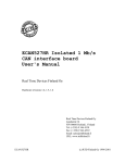
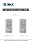
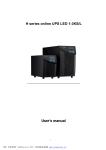
BtmGlobal System Controller User Manual Version 4.0.3 Polytronics Engineering Ltd. 2010 All Rights Reserved 1 Table of Contents Introduction....................................................................................................................... 3 Site Requirements ............................................................................................................... 3 Hardware Overview.......................................................................................................... 4 Hardware Installation ...................................................................................................... 5 Installation ......................................................................................................................... 6 Communication Path Installation............................................................................... 6 Terminating Fiber Optic Cables................................................................................. 6 Hardware Verification and Configuration ................................................................ 7 System Setup and Operation ........................................................................................... 8 Accessing Battery Data ................................................................................................ 8 Summary Page.............................................................................................................. 9 Appendix A: Local Data Access.................................................................................... 10 Connecting Using a Router (Dynamic Addressed Controller) .............................. 10 Appendix B: Controller Alarms and String Status .................................................... 11 Appendix C: Sample Controller System...................................................................... 13 Appendix D: Mechanical System Layouts................................................................... 14 2 Introduction The controller is a real-time, stand-alone battery monitor with full networking support. It is used for storing individual cells/jars and full string data, detecting abnormalities coming from the battery measurements, warning about the changes in the battery condition and alarming when critical conditions occur on an individual Jar(s) or the entire string. Based on the collected data, the controller generates various comprehensive reports for assessing the operational conditions and the health of the battery. The generated reports are presented in Hyper Text Markup Language (HTML) and in Portable Network Graphics formats (various graphs and plots) to utilize the Internet based World Wide Web browsers. Currently, only Mozilla Firefox fully supports all the user interface features. The controller’s network support facilitates TCP/IP protocol over Ethernet. The system is easily accessible (locally or remotely) over Modem for report viewing, data downloading, configuration and system upgrading. The system can also be configured to automatically upload the report-pages to a predefined Web Site and use Email for the remote enunciation of alarms (local ISP access point or local network Gateway access is required). The System Controller supports the following services over TCP/IP network: HTTP: serves battery report pages for WEB-browser FTP: file transfer service SSH: secure shell for remote system configuration/upgrade Mail: electronic mail agent (configured to send alarm messages) Site Requirements • • • Ethernet access (optional) Direct telephone line (optional if remote access/support is required) Uninterruptible power supply 500VA or UPS protected AC outlet 3 Hardware Overview The concentrators are configured either as low voltage or high voltage devices. The high voltage concentrators can serve up to 20 Jars, and the low voltage concentrator can serve up to 30 Jars. There are a few small differences in the equipment depending on whether the system is monitoring 2V or 12V Jars. Although concentrators may look the same, it is important to check the nameplate to tell whether the concentrator has the proper voltage for your application. All concentrators are powered from the battery monitored. However, the controller uses a 120/220 VAC outlet for power. Note: In order to maintain data acquisition during a power failure, the AC outlet must be UPS protected or have an emergency generator as a backup. 4 Hardware Installation Alarm contacts, may be connected to light/bell if desired) AL WD OUT IN Float Current Montior Fiber Optical Cable Concentrator Charger Negative Concentrator Jar #32 Jar #17 Charger Positive Jar #16 Jar #1 Battery String #1 Float Current Montior Concentrator Charger Negative Concentrator Jar #32 Jar #17 Charger Positive Jar #16 Jar #1 Battery String #4 Figure 1: System Connectivity 5 Installation Communication Path Installation Layout the devices and measure the distances between the connection points for the communication loop. The devices are connected in a daisy chain format - from the fiber optics output (blue) of one device and then connected to the fiber optics input (black) of the next. Plan your connections of fiber optical cable to minimize the length of the longest fiber optical cable run. If multiple strings are connected to the single optical loop, then fiberoptical cable must connect across strings (sometimes in another battery room). Take care to keep the radius on all bends at least 2 inches or 40 mm. Care should be taken to run all lengths prior to cutting. Warning: The fiber optical loop must be planned very carefully before cutting the fiber optic cable because there is no way to join cut pieces of fiber optic cable together without any extra equipment. Also, neither the sequence nor the total length of the cable is important. The only important aspect is the length of the longest piece of the cable is. The longest fiber optic cable must not exceed 60 meters. Terminating Fiber Optic Cables The fiber optic cable from the concentrators should be terminated in the appropriate socket in the controller. Prepare the end of the fiber optic cable by cutting it at a right angle with a sharp utility knife. Do not strip the fiber-optic wire. With limited force, a stripped wire can damage the internal receiver and transmitter. Position the prepared end of the fiber optic cable in the input (or output) of the special fiber optic’s connector, be sure the connector is loosened. Push the end of fiber optics cable into the housing; tighten the connector with finger force as much as would be used to close a toothpaste container. 6 Hardware Verification and Configuration Workstations on IP network Remote Workstation Windows Hyperterminal SW Dial-in / Remote data access / remote configuration Data access system configuration BTM-Global Stand-alone system 120/220 Vac (1 A Max) protected power source LAN / WAN PSTN line Internet Explorer HTML Report Pages PWR COM1 KM LAN1 CRT Ethernet access-point Modem Ethernet Cable Internet explorer HTML Report Pages On Site Mobile PC / Laptop Data access system configuration Figure 2: Connecting PC to the Controller 7 System Setup and Operation The controller you have received has been pre-configured for your installation. Reconfiguration of the controller box can be performed remotely over the telephone-line (dial in), Ethernet or locally. Further instructions on configuring and use of the system are incorporated into the monitoring controller web page. Accessing Battery Data The controller system facilitates several means to access data. All necessary battery data is stored in the controller and is also presented in an HTML formatted report file. Any graphics are produced in the PNG (Portable Network graphics) format. Complete access to all data (including raw data) can be achieved by establishing a dial-in network connection, or by connecting the System Controller to a local Ethernet network. The System Controller has a built-in web-server capability and, all HTML report pages can be browsed using a local network connection or over a dial-in network. Raw data, ASCII text tables and other relevant files, can be retrieved using an FTP site. Note: The System Controller is configured for dynamic IP address and should work with any existing network. 8 Summary Page Figure 3: Controller Summary Page The Summary page summarizes data and provides links to all the other areas of the system. It displays information about the batteries themselves: the status, alarms, charge level, voltages, current, ripple current, ambient and pilot temperatures of the string are displayed. Clicking on the logo in the top right side opens up a FAQ for the controller. 9 Appendix A: Local Data Access Connecting Using a Router (Dynamic Addressed Controller) 1. Connect the PC, router and Controller(s) as shown in Figure 4. To Other Equipment Local PC Ethernet Cable Ethernet Cable Ethernet Cable Ethernet Cable Figure 4: Connection of Controller, Router and PC 2. Start your web browser (Mozilla Firefox and in the address bar type btmGlobalXX, where XX is digits 01 – 99. The Controller name is recorded on the front label. 10 Appendix B: Controller Alarms and String Status Alarm String Exhausted Bit Position 1 String Open 2 Pending Jar Reversal 3 Low Capacity 5 Jar Internal resistance High 6 Jar Voltage Below set limit 7 Jar voltage Above set limit 8 Jar High Float Mobility 10 Jar High Noise during Float Temperature Abnormalities Discharge Warning Charge Warning Equalization Warning Jar Parameters Degraded 9 12 13 15 14 16 Ground Fault 17 Description Battery total voltage is below discharge end voltage (during discharge) String is at open potential, charger not connected or malfunctioning A jar terminal voltage is near its end voltage during discharge. This jar does not support the load any longer. String capacity near exhaustion, a few minutes reserve time remaining The internal resistance of a jar has increased drastically. During float operation, the jar terminal voltage is below preset limit. During float operation, the jar terminal voltage is above preset limit. Jar terminal voltage drifts significantly during battery floating High ripple voltage during float operation Ambient/Pilot temperature outside limits String is discharging String is charging String is at Equalization potential Jar calculated parameters during discharge, charge or Float have been degrading. When using a ground fault detector, the limit at which it alarms has been passed and ground fault condition is present. Note: Each alarm can be individually enabled or disabled. The controller can send an e-mail when an alarm is detected if it is connected to the LAN or has a dial-out to the ISP capabilities enabled. String Status NA OPEN FLOATING FLOAT-CHARGING Description String status unknown. During a system start-up or communication failure String is at open potential String is fully charged and floating at its nominal voltage Battery capacity is not fully restored. 11 CHARGING EQUALIZING DISCHARGING Charging current to the battery detected. Battery at equalizing potential (prolonged application will be harmful to the battery). Load is on the battery. 12 Appendix C: Sample Controller System Local Workstations Internet Explorer HTML Report Pages Remote Workstation Windows Hyperterminal SW PSTN line Dial-in / Remote data access / remote configuration Ethernet interface (RJ-45 for 10/100Mbs): TCP/IP protocol: - HTML server - FTP server PWR PSTN Interface: external modem (optional) COM1 KM LAN1 CRT LAN 120/220 Vac (1 A Max) protected power source Ethernet access-point Rs232 cable Cross-over network cable Internet explorer HTML Report Pages On Site Workstation Out BTM4000I Concentrator ID #3 In T Sensor Charger Negative Jar #32 Jar #17 BTM4000I Concentrator ID #1 Charger Positive Jar #16 Jar #1 Battery String #4 Current Shunt (not required if current is less than 400A and Factstar option is selected) Figure 5: Sample System Setup 13 11.65 (296) 0.63 (16) 0.39 (10) 7.4 (188) 4.61 (117.1) 2.32 (59) 0.197 (5) PLASTIC FIBRE OPTICS 3.94 (100) 2.17 (55) TOP VIEW BTM GLOBAL CONSOLE 0.39 (10) FACTSTAR CURRENT TRANDUCER 0.24 (6) TOP VIEW 1.77 (45) 1.65 (42) TOP VIEW 7.52 (191) 0.24 (6) 0.24 (6) ALARM CONTACTS 1.34 (34) 3.58 (91) 18 CONNECTOR TERMINAL BLOCK 3.19 (81) 16 CONNECTOR TERMINAL BLOCK 9.84 (250) 0.39 (10) 0.31 (8) 2.48 (63) BTM CONCENTRATOR 4.88 (124) WALL MOUNTED CONCENTRATOR Appendix D: Mechanical System Layouts 3.35 (85) 0.24 (6) 3.54 (90) TEMPERATURE SENSOR 0.197 (5) 2.05 (52) CT ALL DIMENSIONS ARE IMPERIAL (MILLIMETERS ARE IN BRACKETS) BTM GLOBAL COMPONENTS MECHANICAL LAYOUT NOV 20,2006 SCALE 1:4 Rev. A 1 OF 2 Figure 6: Mechanical Layout 14 SIDE VIEW SIDE VIEW SIDE VIEW 1.25 (31.75) 1.42 (36) 0.25 (6.35) FLOAT CURRENT TRANSDUCER FRONT VIEW FRONT VIEW B- 28 26 24 22 20 18 16 14 12 10 8 6 4 2 B1+ B+ 29 27 25 23 21 19 17 15 13 11 9 7 5 3 1 BC HC CONCENTRATOR FRONT VIEW SYSTEM CONTROLLER BTM GLOBAL COMPONENTS MECHANICAL LAYOUT UNDER BATTERY RACK MOUNTED COMPONENTS ALL DIMENSIONS ARE IMPERIAL (MILLIMETERS) NOV 20,2006 SCALE 1:4 Rev. A 2 OF 2 Figure 7: Mechanical Layout 15 ALL HOOK-UP WIRES: TINNED COPPER, PVC INSULATED, STRANDED, AWG 18, 600V ,105C (BELDEN STYLE 1015 OR EQUIVALENT) OR TINNED COPPER, POLYOLEFIN (XLPE) INSULATED, STRANDED, AWG 18, UL AWM STYLE 3265 105°C, 600V. SUPPLIED BY INSTALLER. WIRE LENGTH BETWEEN CONCENTRATOR TERMINAL AND BATTERY POST SHOULD NOT EXCEED 100FT (30M). FLOAT CURRENT TRANSDUCER FIBER OPTICS OUT TO BTM CONCENTRATOR +12V FROM SYSTEM CONTROLLER POWER GND FROM SYSTEM CONTROLLER FIBER OPTICS IN FROM BTMGLOBAL CONSOLE CURRENT TRANSFORMER BLACK LEAD TEMPERATURE SENSOR LEAD TEMPERATURE SENSOR LEAD TEMPERATURE SENSOR CURRENT TRANSFORMER RED LEAD CT SECOND COM PORT TO MODBUS INTERFACE PLASTIC FIBER OPTICAL CABLE (SMF) SUPPLIED WITH THE SYSTEM. LONGEST FIBER OPTICAL SEGMENT MUST NOT EXCEED 100FT (30M) . TO MODBUS INTERFACE 2 OR 4 WIRE RS485 VGA INTERFACE (OPTIONAL MONITOR) ETHERNET INTERFACE 12V DC, 2A MAX POWER SUPPLY (SWITCHING) DC-DC POWER CONVERTER OPTION, OUTPUT: 12V DC, 2A MIN KBD/MOUSE INTERFACE RS485 CONVERTER NOT SUPPLIED WITH THE SYSTEM RECOMMENDED MODEL: 485OT9L B&B ELECTRONICS BtmGlobal SYSTEM CONTROLLER +12V FROM SYSTEM CONTROLLER POWER GND FROM SYSTEM CONTROLLER TO AC OUTLET: 100 - 240 VAC 50/60 HZ BATTERY: 24VDC 48VDC 96VDC 120VDC 240VDC FIBER OPTICS OUT TO FLOAT CURRENT TRANSDUCER FIBER OPTICS IN FROM BTM CONCENTRATOR +12V TO FLOAT CURRENT TRANSDUCER (OPTIONALLY TO RS485 CONVERTER) POWER GND TO FLOAT CURRENT TRANSDUCER (OPTIONALLY TO RS485 CONVERTER) INTERNAL COM FAILED ALARM CONTACT BATTERY ALARM CONTACT ALARM RELAY CONTACT RATING: SWITCHING POWER: 10W SWITCHING VOLTAGE: 100VDC SWITCHING CURRENT: 500 mA BTMGLOBAL COMPONENT CONNECTIONS: SYSTEM CONTROLLER AND FLOAT CURRENT TRANSDUCER NOT TO SCALE JAN 10,2007 Rev. B 1 OF 1 Figure 8: Mechanical Layout 16